...
| Include Page | ||||
|---|---|---|---|---|
|
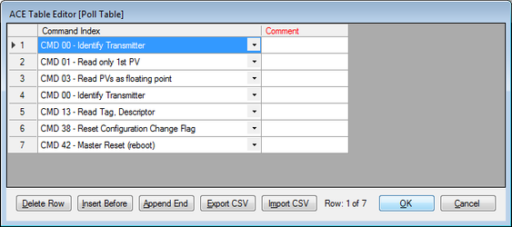
In the HART FieldUnit's Poll Table, every command must be included that is intended to be supported by the RediGate. But as with all other FieldUnit types, it is not required to scan all of those polls in real-time. For instance, a typical Poll Table is shown below that includes seven polls defined in the HART Command objects.
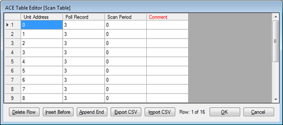
But Although the Poll Table might contain many Command Index entries, the Master Channel might be configured to poll only poll for the 3rd Poll Record (CMD 03 - Read PVs as floating point), as shown below. This allows the primary process variables to be read continuously for each of the configured HART devices.
Note that the a Scan Period of 0 milliseconds is used to indicate obtain the maximum HART scan rate, but the actual communication delays are determined by built-in timing in required by the HART protocol, which makes the effective scan rate about 2-3 polls per second. Any non-zero Scan Period will add additional poll delay beyond the timing required by the HART protocol.
Although in the example above the Master Channel is only scanning for HART CMD 03 continuously, the other polls in the HART FieldUnit's Poll Table may be requested on demand using the device's Command Register (see RediGate-HART-Master).
...
| Properties | Values |
|---|---|
| Command Register | The Command Register is an integer register in the HART FieldUnit RTDB which is used to request the RediGate to send a HART command on demand. To force a command in this device's Poll Table to be executed on demand, write into the Command Register the Poll Record row number of the poll to request. Note that the Command Register is the Poll Record number, not the actual HART command number. It is therefore recommended to configure the Poll Table for similar HART devices to be in an identical order, to avoid confusion over which Command Register value to use. After a command is operated by writing to the Command Register, the resulting value in the Command Register indicates what was the result of the previous command, which may be read and acted on by a host system or internal RediGate logic. The result values that appear in the Command Register are:
|
| Response Register | The Response Register is an integer register in the HART FieldUnit RTDB that will contain the two Command Status bytes included in each response from a HART device. The least-significant byte (LSB) in the Response Register contains the Field Device Status (2nd byte of HART Status):
The next most-significant byte (MSB) in the Response Register contains the 1st byte of the HART Status. This is either a command-specific Response Code, or a communication or command response error.
|
| #Timeouts to Identify | Enter the number of communication timeouts before the RediGate will revert to an Identity command to identify the HART device again. This should typically be a low number (default is 5). The polling logic for the HART master protocol is:
|
| Reserved | Unused property |
...