...
- Using ACE, open the default config you used in the "Getting Started Guide"
Download and open the Elecsys-MELSEC-Demo.xml from the http://partner.elecsyscorp.com site within the same ACE window as the configuration you used in your "Getting Started Guide"
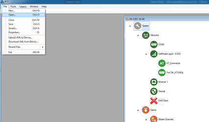
- You will need to extract the .xml file from the .zip file you downloaded from the website. By default, ACE stores configuration files in the Documents\Elecsys\ACE\CFG folder, but you can store the configuration in any file location accessible by the ACE program..
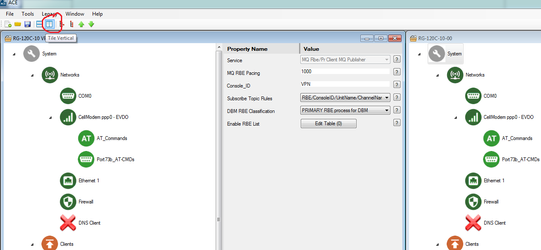
- You cannot copy/paste nodes unless both configurations are open within the same instance of ACE. You can use the "Tile" buttons to have the windows automatically size themselves within the ACE program:
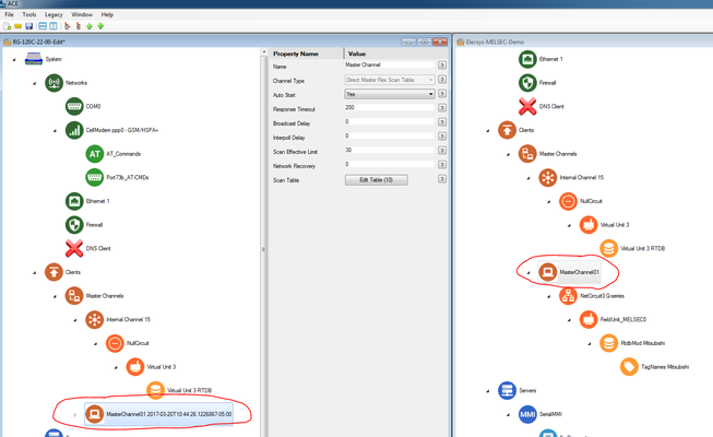
- Copy the "MasterChannel01" channel from the Elecsys-MELSEC-Demo.xml and paste the node into your configuration:
Edit the "NetCircuit0 Q-series
" →→ Connect Table" to have the IP address of the PLC you will be connecting to. Do not worry about the "Interface" column; it is only used for legacy protocols.

Info title Master Network Port The "Master Network Port" is set to 5002 in the example configuration. While this is the default setting for the PLC, it should be edited to match the setting on the QJ71E71-100 or equivalent Ethernet card.
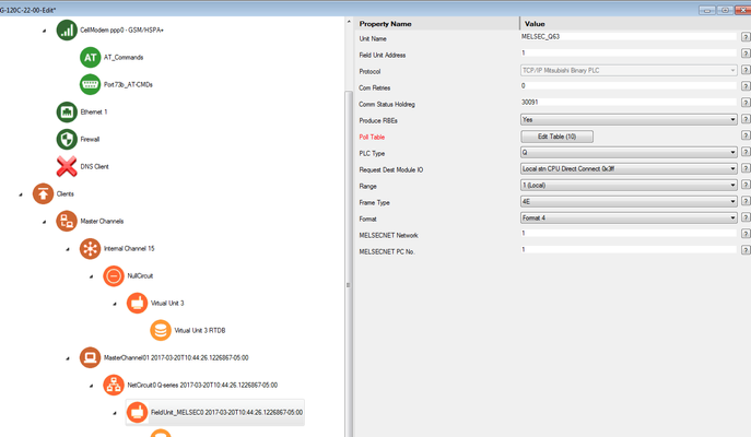
Under the "FieldUnitABDF1M_RTU- Under the "FieldUnit_MELSEC0" object, edit the properties to match that of the QJ71E71-100 or equivalent Ethernet card:
(Example settings on QJ71E71-100)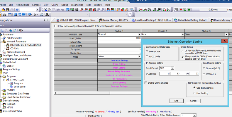
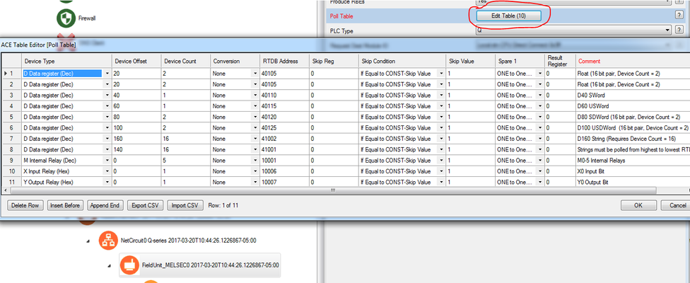
Also under the "FieldUnit_MELSEC0" object, edit the "Poll Table" to
pollmatch the
correctregisters
onin your PLC:
 In the screenshot above, we are polling $F8:0 for a count of 2 and storing the data starting in the RTDB address of 42001: in the next step we will create the database of registers that are used to store these polled values.
Edit theWarning title Polling registers that do not exist You must have data in the registers that you are polling, otherwise you receive errors on that poll record during that poll attempt. For example, there are only 2 $F8 registers declared in this PLC program:

Attempting to poll register $F8:2 will result in an error.
(Example global label database from PLC program)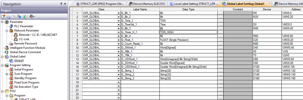
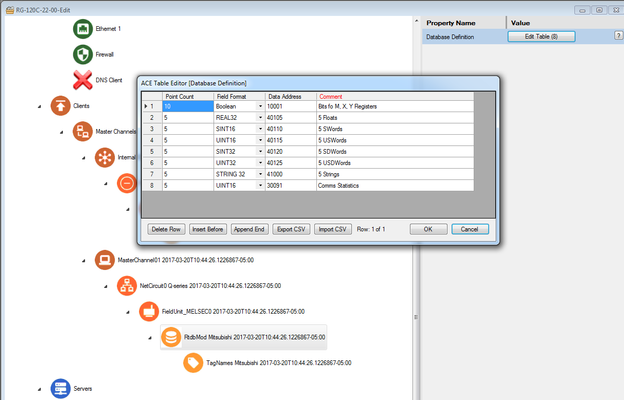
Edit the "DF1_RTDB → Database Definition" table so that it contains enough registers of the correct datatypes to store all of the polls created in the previous step:

- In the above example, 5 registers were created in 30001 for the status bits coming from the RTU object, and 2 registers were created for the integers, floats, and bools we are polling
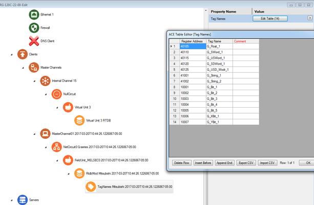
- Edit the "TagNames Mitsubishi → Tag Names" table to add tag names for the registers you are polling:

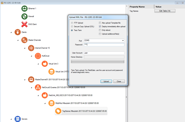
- Save and upload the configuration to the RediGate (File → Upload XML to Device)

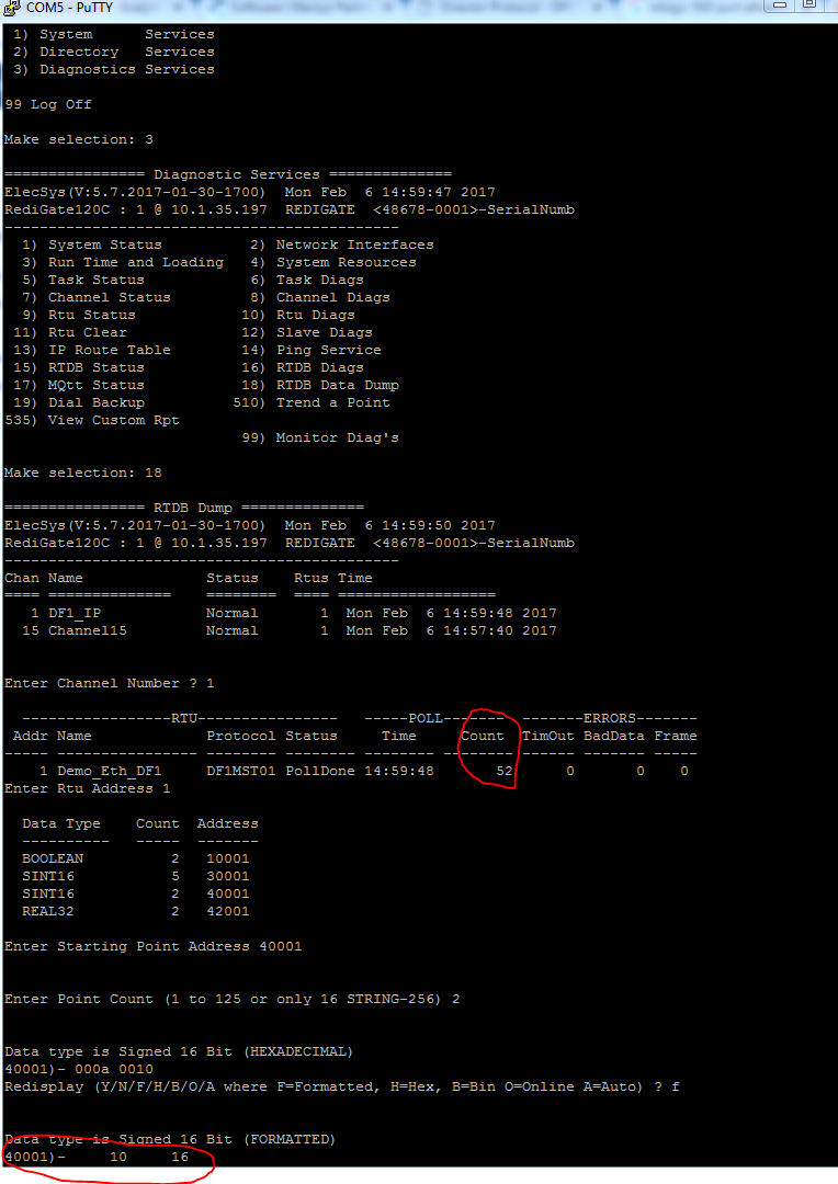
- Create a Putty session into the RediGate to confirm that the RediGate is successfully polling the tags. You may get some errors on start-up, but if you see the Poll Count field incrementing, your RediGate is configured correctly.
...