| Expand | ||||||
|---|---|---|---|---|---|---|
| ||||||
|
| Anchor | ||||
|---|---|---|---|---|
|
| Table of Contents | ||
|---|---|---|
|
...
Introduction
The RediGate Configuration Manual describes the configuration of many of the RediGate's standard features using the ACE program. This document gives additional instructions for configuring the RediGate to use the following protocol:
...
| Include Page | ||||
|---|---|---|---|---|
|
EtherNet/IP Protocol Description
This document is not intended to provide a detailed description of the protocol(s) involved, nor to disclose proprietary information that may belong to other parties. Depending on the protocol, it may be necessary to refer to other vendor protocol documentation or device configuration details to understand how the RediGate should be configured to interface with it. This section provides a brief discussion of the protocol for the purpose of understanding the RediGate's configuration objects.
...
The Description and Enabled properties are included in ACE as part of each object but are not mentioned here. The "UFF External" property is only mentioned for the objects where it is typically used, but should normally be left unchecked.
Supported Features and Limitations of EtherNet/IP Master
CIP objects may contain complex arrays and nested structures of data organization. In order to simplify the process of creating RediGate configurations, Elecsys provides a tool for converting the PLC configuration file (L5X) into the tables necessary for configuring the Scan Table, Poll Table, RTDB, and TagName tables.
...
If an external Modbus host is reading PLC data from the RediGate using a Modbus Slave Channel, then there are special requirements for the organization of RTDB registers (see the "Modbus Slave Attach" section of the RediGate Configuration Manual).
Using the L5X Tool
See the Ethernet/IP Master Quick Start documentation for instructions on using the Elecsys "L5X Import Tool." The steps are summarized here:
...
- ATOMIC and ARRAY BOOL – registers starting at 00,001
- UDT/PDT SINT and INT – registers starting at 30,001
- ATOMIC and ARRAY SINT (8-bit) and INT (16-bit) – registers starting at 40,001
- ATOMIC and ARRAY DINT (32-bit) – registers starting at 45,001
- UDT/PDT DINT (32-bit) – registers starting at 45,001
- ATOMIC and ARRAY REAL (32-bit float) – registers starting at 47,001
- UDT/PDT REAL (32-bit float) – registers starting at 47,001
- 64-bit Int – 63,001
- STRING (up to 80 characters) – registers starting at 65,001, length value at 45,xxx
EtherNet/IP Master Channel
The structure of ACE objects for a Master Channel used for the EtherNet/IP protocol is shown below:
...
- Response Timeout needs to be set greater than the Scan Period - this is because the RediGate uses the Response Timeout to notify the EtherNet/IP PLC of what period it should expect to be polled (or else the PLC may shut down its open socket prematurely).
- The Scan Table should be imported from a CSV file created by the L5X Import Tool. The PLC polling setup can get somewhat complicated, so it is not recommended to modify the table by hand.
- If the configuration includes more than one EtherNet/IP device, either configure them under different Master Channels, or you will need to merge the Scan Table for more than one PLC.
Network Circuit
![]()
![]()
A Network Circuit is an IP network communications path to one or more field units from a common Master Channel. The Network Circuit is used when the field unit is connected to the RediGate over a TCP/IP network.
...
See the RediGate Configuration Manual for information on configuring the NetCircuit object.
EtherNet/IP FieldUnit
![]()
An EtherNet/IP FieldUnit object contains unique information for each Field Unit using the EtherNet/IP communication protocol, and defines parameters for how data is read and written for the device.
...
The Continuation Poll may be used either to poll a structure, or it may be used to poll a block of Atomic elements that aren't in a structure. See the Poll Table description and Examples of EtherNet/IP Polls below for more details.
| Info |
|---|
| NOTE: The Scan Table in the Master Channel should only request the FIRST row in the Poll Table defining the "continuation poll" (with non-zero Read Count), not the subsequent rows of the continuation. |
...
| Poll Table Properties | |||||||
|---|---|---|---|---|---|---|---|
| Properties | Values | ||||||
| TagName or Table-Ref | To poll discrete Atomic element(s) – Enter either the name of the Atomic Element (up to 40 characters), or enter '+' to look up the tag in the TagNames object. To poll an Array – Tag name should be the name of the array, followed by the starting element in square brackets, such as: MyIntArray[3] To poll a Structure – Enter either the name of structure, or '+' to look up the Structure name in the TagNames object. Tag names with dots may be interpreted by some MQTT hosts as a nested tag name hierarchy. | ||||||
| Data Type | Select the data type of the data being read in this row of the Poll Table. If the Read Count of points contains data of different types, use multiple rows to define the number of points to read for each Data Type and the Destination Register in which to store each set of data. Select the data type from:
| ||||||
| Read Count | For Atomic elements – Enter 1 for a single element or in the first row in a Continuation Poll. Enter 0 for the remaining Atomic elements in a Continuation Poll. For an Array – If polling a single Array, enter the number of array elements in both the Read Count and Write Count. For a Structure – If polling for a structure, use multiple rows in the Poll Table as a "Continuation Poll." | ||||||
| Write Count | For Atomic elements – The Write Count must be 1 when polling an individual element. For an Array – Enter the number of array elements to store into the RTDB. For a Structure – If polling for a structure, use multiple rows in the Poll Table as a "Continuation Poll." | ||||||
| RTDB Destination Address | Enter the starting destination register within the field unit's RTDB into which the Write Count of data points will be stored. These registers must be configured in the RTDB object. The Destination Register type should be chosen based on the Data Type of the data points defined on this row of the Poll Table. | ||||||
| Skip Reg | The Skip Reg and following parameters allow an advanced level of control over the poll messages sent to the device. This feature allows logic (ISaGRAF, POD) or other controls to modify the polling of individual commands to the device. Enter an integer RTDB register address from this FieldUnit's RTDB which will be checked before issuing the poll record. The value in the register will be compared with the Skip Test and Skip Match properties. If the condition is satisfied, then the poll is handled according to the Skip Test setting. Enter 0 to disable this feature, or when using one of the last three Skip Test options (below). | ||||||
| Skip Test | Select a condition to use for poll modification. Equal Constant Match – If the value in Skip Reg register is equal to the Skip Match value (constant), the poll is skipped. If Equal RtdbReg Match – If the value in Skip Reg register is equal to the value contained in the register pointed to by Skip Match, the poll is skipped. NO SAVING Data with this Record – If using this Skip Test condition, the data elements in the Poll Table row are discarded and not stored in the RTDB. (Use 0 for Skip Reg and Skip Match.) SAVE Integer to Hidden Buffer for Bit Extraction – When polling bit-packed integers, use this Skip Test condition to store the integer value into a hidden non-RTDB buffer temporarily for later extraction of bits. (Use 0 for Skip Test EXTRACT BIT from Hidden Integer Buffer – Must follow the "Save Integer to Hidden Buffer for Bit Extraction row in the Poll Table." These can include "ZZZZZZZZZZ" entries to discard unneeded bits. Read=Write=1. | ||||||
| Skip Match | For "Constant Match" Skip Test selections, enter a constant value that will be used for the match criteria. For "RtdbReg Match" Skip Test selections, enter the address of a register in this FieldUnit's RTDB which contains the value used for the match criteria. | ||||||
| Save Reply | Enter the address of a register in this FieldUnit's RTDB which will contain the length of the reply message (in bytes) from the PLC. This is only valid for the first row of a Continuation Poll. The Save Reply feature allows the length of a successful poll to be saved to the RTDB, which could be the same as a Skip Reg register used to skip a poll on the next poll cycle once it has been received successfully. Set the Save Reply column to 0 if you don't wish to store the length of the reply message. | ||||||
| Comment | The Comment column is an optional field, allowing a description to be entered for each row in the table. This is only for the user and has no effect on the operation of the RediGate. | ||||||
| Anchor | ||||
|---|---|---|---|---|
|
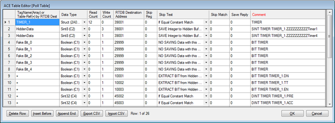
The following examples show different cases of using the EtherNet/IP Poll Table.
...
Row 4 parses and discards five bits from Timer4, then stores three Booleans from the timer (DN, TT, and EN) into 10001-10003, and two integers (PRE, ACC) into 45002-3.
RTDB
See the RediGate Configuration Manual for information on configuring the RTDB.
The RTDB table should be imported from a CSV file created by the L5X Import Tool. The PLC polling setup can get somewhat complicated, so it is not recommended to modify the table by hand.
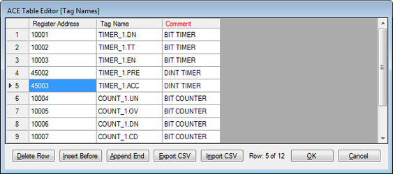
Tag Names
See the RediGate Configuration Manual for information on configuring the TagNames object.
...