
Product Information
Full information about other Elecsys products is available on our website at www.elecsyscorp.com and the RediGate Product Support Page, http://redigate.elecsyscorp.com.
Product Support
Tel: +1-913-890-8905
Fax: +1-913-982-5766
Email: idc-support@elecsyscorp.com
Headquarters, Sales, Support & Manufacturing
Elecsys Corporation
846 N Mart-Way Court
Olathe, KS 66061
Tel: +1-913-647-0158
Fax: +1-913-982-5766
Email: info@elecsyscorp.com
While Elecsys may assist customers with their choice of products, the final choice of product for a specific application is entirely the responsibility of the buyer. Elecsys' entire liability with respect to its products or systems is defined in the Elecsys standard terms and conditions of sale.
Any example code is provided only to illustrate the use of Elecsys products. No warranty, either expressed or implied, is made regarding any example code provided by Elecsys and Elecsys shall incur no liability whatsoever arising from any use made of this code.
Disclaimers
The information in this manual is believed to be accurate at the time of publication. Elecsys Corporation assumes no responsibility for inaccuracies that may be contained in this document and makes no commitment to update or keep current the information contained in this manual. Elecsys Corporation assumes no responsibility for any infringements of patents or other rights of third parties that may result from its use. Elecsys Corporation reserves the right to make changes or improvements to this document and/or product at any time and without notice. While Elecsys may assist customers with their choice of products, the final choice of product for a specific application is entirely the responsibility of the buyer. Elecsys' entire liability with respect to its products or systems is defined in the Elecsys standard terms and conditions of sale.
Any example code is provided only to illustrate the use of Elecsys products. No warranty, either expressed or implied, is made regarding any example code provided by Elecsys and Elecsys shall incur no liability whatsoever arising from any use made of this code.
Electrostatic Discharge (ESD) Protection
These units contain devices that could be damaged by the discharge of static electricity. At all times, please observe industry standard ESD precautions when handling the unit.
![]() WARNING: DO NOT CONNECT OR DISCONNECT CABLES WHEN ENERGIZED, UNLESS POWER HAS BEEN REMOVED FROM THE EQUIPMENT OR THE AREA IS KNOWN TO BE FREE OF IGNITABLE CONCENTRATIONS OF FLAMMABLE SUBSTANCES.
WARNING: DO NOT CONNECT OR DISCONNECT CABLES WHEN ENERGIZED, UNLESS POWER HAS BEEN REMOVED FROM THE EQUIPMENT OR THE AREA IS KNOWN TO BE FREE OF IGNITABLE CONCENTRATIONS OF FLAMMABLE SUBSTANCES.
© 2017 Elecsys Corporation
Table of Contents
Introduction
The RediGate Configuration Manual describes the configuration of many of the RediGate's standard features using the ACE program. This document gives additional instructions for configuring the RediGate to use the following protocols:
- Allen Bradley DF1 (serial) Master
- Allen Bradley DF1/PCCC (TCP/IP) Master
- Allen Bradley CSP/PCCC (TCP/IP) Master
See the following Quick Start example configuration:
- DF1 Master Example (the example is for DF1 over a NetCircuit, but can be applied to DF1 through serial using an AsyncCircuit)
The RediGate is a multi-application remote data communications computer/data integration device. It provides a wide array of SCADA and other communication and logic processing functionality. In order to configure the operational characteristics of the RediGate, Elecsys provides the ACE Configuration Editor. This manual assumes that the user is already familiar with the use of ACE and that the RediGate being configured includes software support for the above protocols.
Within the ACE Editor, each configuration object is represented by an icon and contains general properties and specific fields that provide operational settings for the RediGate. This manual provides reference information on the configuration objects within the ACE Editor, specific to the FieldUnit protocol(s) listed above.
Allen Bradley DF1 & CSP Protocol Description
This document is not intended to provide a detailed description of the protocol(s) involved, nor to disclose proprietary information that may belong to other parties. Depending on the protocol, it may be necessary to refer to other vendor protocol documentation or device configuration details to understand how the RediGate should be configured to interface with it. This section provides a brief discussion of the protocol for the purpose of understanding the RediGate's configuration objects.
Data from an Allen Bradley PLC using DF1 or CSP protocols is requested using a "file" identifier and a register number within that file as the specified starting address. The file may contain a mix of different data types. The RediGate's Poll Table is able to read a block of registers from the PLC and parse them into Real-time Database (RTDB) registers using the appropriate data types.
DF1 protocol can be used on Rockwell/Allen-Bradley devices:
- PLC5, SLC500/xx, MicroLogix, and CPU Logix5000 series;
- ControlLogix, CompactLogix, and FlexLogix5434 (using "Tag/File Mapping")
(see Setting up PLC/SLC Mapping in Logix controllers)
The RediGate's DF1 and CSP protocols over an Ethernet connection is also referred to as PCCC. This document does not describe configuration of Allen Bradley EtherNet/IP CIP protocol. The RediGate does not currently support Data Highway Plus (DH+), which requires a special hardware interface.
The following sections describe the ACE objects used for DF1 and CSP Master, object properties (including constraints on the Instance number), and object fields and their possible values required to configure for the given protocol(s). The object structure in ACE is hierarchical, with each object existing under a certain parent object. For instance, the FieldUnit is the child of one of several types of Circuit objects, either serial or network type (" System>Clients>Master Channels>Master Channel>Circuit").
The Description and Enabled properties are included in ACE as part of each object but are not mentioned here. The "UFF External" property is only mentioned for the objects where it is typically used, but should normally be left unchecked.
DF1/CSP Master Channel
The structure of ACE objects for a Master Channel used for DF1 or CSP protocol is shown below:
| DF1 Serial | DF1/PCCC Master | CSP/PCCC Master |
|
|
|
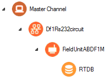
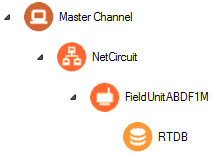
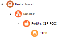
The RediGate uses the Master Channel and its child objects to define the RediGate's ability to act as a master for reading or writing other devices using one or more device protocols. All master protocols use the same basic structural definition, requiring at least four ACE objects to be configured:
- The Master Channel defines the sequence and timing of periodic scans of the device, independent of protocol.
- The Circuit (network or serial) defines the physical connection to the device.
- The FieldUnit object defines the protocol-specific characteristics and poll definitions for the device.
- The Real-time Database (RTDB) defines a data structure for storing information obtained from each physical field device.
- Other optional child objects under the RTDB or FieldUnit provide other features for acting on the device's data.
In the Master Channel configuration, make sure that the Response Timeout is set long enough to receive replies for the given network and field devices. Add rows in the Scan Table for each poll in each FieldUnit that is required to be scanned in real-time.
For general information on configuring Master Channels, see the RediGate Configuration Manual.
Note the following when configuring the Master Channel for DF1/CSP devices:
- When using DF1 serial master, the Response Timeout is unused, because the AsyncCircuit object defines various timeouts for the DF1 protocol.
- In the Scan Table, only include the first Poll Record of a "Continuation Poll," not any subsequent poll records that are part of the same poll definition.
DF1 RS-232 Async Circuit
![]()

The DF1 RS-232 Async Circuit is a special serial communications path to one or more Allen Bradley DF1 field units from a common Master Channel. Use this circuit instead of the generic AsyncCircuit when configuring a DF1 serial field unit under a Master Channel. You should not use the standard AsyncCircuit when polling DF1 PLCs.
| Attributes | Function |
|---|---|
| Object Type | Df1Rs232circuit |
| Parent(s) | System → Clients → Master Channels → Master Channel |
| Instance | Should be set to 0. Only one circuit (Network or Async) is allowed when using the DF1 master protocol. The DF1 Async Circuit should have at least one Field Unit child object defined under it. |
| Properties | Values |
|---|---|
| DH Link Type | Select the Allen Bradley link type (DH or DH+). Configure this to "DH." The RediGate does not currently support the Data Highway Plus (DH+) protocol, which requires special hardware. |
| Station DHP Address | Enter the DF1 (master) station address taken by the RediGate on the Data Highway network. Note that the master station address is different from the device address being polled, which is configured under the FieldUnit definition. |
| Link Protocol | Select the link protocol to use ('Full Duplex' or 'Half Duplex'). This should be set to match the full-duplex (peer to peer) or half-duplex setting of the PLC. |
| Serial Port | Select the Async serial port to use for this circuit. The selected port must be defined as an AsyncPort object under Networks, where its serial properties (baud rate, etc.) are defined. |
| Message Timeout | Enter the message timeout in milliseconds. This is the amount of time to wait for a message response. In the DF1 protocol, there may be multiple messages to a single poll, such as acknowledgments. |
| Message Timeouts | Enter the number of message timeouts before declaring a message to have failed. |
| Poll Timeout | Enter the poll timeout in milliseconds. This is the amount of time to wait for the initial byte of a response to a poll. For DF1 used on an Async Circuit, the Master Channel's Response Timeout parameter is unused. |
| Poll Timeouts | Enter the number of poll timeouts before aborting a poll request. |
| Demark Timeout | Enter the byte timeout in milliseconds to wait for the last byte of a packet. The Demark Timeout is used to help identify the end of a packet after the RediGate has started receiving bytes on the serial port. |
| Error Check | Select the error check type (BCC, or CRC-16). |
Network Circuit
![]()
![]()
A Network Circuit is an IP network communications path to one or more field units from a common Master Channel. The Network Circuit is used when the field unit is connected to the RediGate over a TCP/IP network.
To configure the Network Circuit for Allen Bradley PLCs:
- For the DF1 protocol, do not use the actual TCP port in this for the Master Network Port. The RediGate will automatically default to using port number 44818.
Instead, set the Master Network Port property to the slot number in the PLC containing the PLC CPU. Often, this will be 0, but check with the PLC setup. - For the CSP protocol, use Master Network Port = 2222.
- Set the Circuit Type to be "Network DF1 Circuit" (not the default "Network Circuit" option).
- Set the Connect Table to the IP address of the PLC.
See the RediGate Configuration Manual for information on configuring the NetCircuit object.
AsyncPort
![]()
![]()
If using a Df1Rs232circuit for serial DF1 devices, make sure to include a COM port (System>Networks>AsyncPort) object in the configuration with the instance number matching the physical COM port, and the baud rate corresponding to the field device’s setting.
See the RediGate Configuration Manual for information on configuring the AsyncPort.
DF1/CSP FieldUnit
![]()


A DF1 or CSP Field Unit object contains unique information for each Field Unit using the Allen Bradley PLC communication protocols, and defines parameters for how data is read and written for the device.
If the PLC "file" includes mixed data types, the RediGate uses a technique called "continuation polls" to optimize polling data. This method allows for one row in the Poll Table to be defined as the actual "poll" that requests data from the PLC, and subsequent rows (with Read Count=0) simply parse the data sequentially from the response obtained in the original poll.
| Attributes | Function |
|---|---|
| Object Type | FieldUnitABDF1M (Allen Bradley DF1 serial or PCCC) FieldUnit_CSP_PCCC (Allen Bradley CSP) |
| Parent(s) | System → Clients → Master Channels → Master Channel → Df1Rs232circuit (serial) System → Clients → Master Channels → Master Channel → NetCircuit (TCP) |
| Instance | Must be unique under a Circuit. |
| The Field Unit must have an RTDB child object defined under it. | |
| Properties | Values |
|---|---|
| Unit Name | Enter the field unit name. Unit name is displayed in diagnostic menus, in HCP diagnostic screens, and may be used as part of an MQTT topic name. |
| Unit Address | Enter the actual field unit address which is configured in the device being polled. |
| Circuit Type | Placeholder for Protocol type of 'Allen-Bradley DF1 Master' or 'AB CSP/PCCC Master'. |
| Com Retries | Enter the number of communication retries after a failed poll attempt. If a poll attempt fails, the RediGate will issue the poll again up to the configured number of "Com Retries" before the field unit is declared failed. For devices on a Network Circuit, you should probably keep the number of protocol retries low (0 or 1), because TCP/IP has its own network retries. |
| Comm Status Holdreg | Enter the starting holding register to contain the communication status for this FieldUnit. Each Comm Status takes 5 registers, beginning at the register configured in this parameter. The Comm Status Holdreg for each field unit in a configuration must be defined such that the five registers do not overlap other registers being used. If the register is defined in the 30,xxx address range, the status values will be stored in the local device's RTDB (i.e., the RTDB defined as a child to this FieldUnit). If the register is in the 40,xxx range, the values will be stored in the Status/Control Field Unit RTDB. The Comm Status Holdreg is optional, and can be set to 0 to disable the storage of status registers. See the section Communication Status Registers in the RediGate Configuration Manual for a description of the five Comm Status Register contents. |
| Produce RBEs |
Select this option to determine whether to produce a Report by Exception (RBE) flag when data in this unit's RTDB changes. In the RTDB, for every data point, there are potentially 4 RBE flags associated with every data point. When the data point changes, the RBE flags are set. The RediGate's HCP and MQTT publishing processes use these flags to determine when new data needs to be reported. |
| Poll Table | Click the Edit Table button to define the polls to be sent to this FieldUnit. Note that the Poll Table only defines how the protocol is defined to operate for each set of data defined in the polls. The Poll Table doesn’t actually do any of the polling itself. If you want any of these polls to be sent to the FieldUnit on a regular basis, it should be referenced in one or more Scan Table entries in the Master Channel. Poll Table entries may be defined which are only used for pass-through writing to the device, not scanned regularly by the Master Channel. Protocol-specific properties for the Poll Table are described in the following table. |
| Poll Table Properties | |
|---|---|
| Properties | Values |
| DF1 Address | Enter the starting source register in the DF1 (or CSP) device to begin polling data. This will be found in the documentation for the device, based on the information that you want to obtain. This field should be set the same in each row of a "continuation poll." The DF1 Address should be entered in one of the following formats, based on the PLC Addressing Type (below):
|
| PLC Addressing Type | Select the PLC addressing type of the DF1 Address entered in the previous column (above). This field should be set the same in each row of a "continuation poll." PLC-2 Logical PLC-2 Physical PLC-5 Logical Binary PLC-5 Logical ASCII |
| Data Type | Select the data type of the data being read in this row of the Poll Table. If the Read Count of points contains data of different types, use multiple rows to define the number of points to read for each Data Type and the Destination Register in which to store each set of data. Select the data type from:
|
| Read Count | Enter the count of points to read from the device. If polling for a block of data from a single "file" with different Data Type and/or Destination Register range, use multiple rows in the Poll Table. The Read Count on the first row of a continuation poll should include the total number of registers to include in the DF1 protocol request, with the Write Count defining how many points of a specific data type to save into the RTDB. Set the Read Count to zero (0) on subsequent consecutive rows of the same poll definition, to indicate a "continuation poll." |
| Write Count | Enter the count of points to store into the RTDB Destination Register. If polling for a block of "file" data with different Data Type and/or Destination Register range, the Read Count is set to zero (0) on all rows after the initial row of the "continuation poll." In all cases, the Write Count should include only the count of points to parse from the message using the Data Type specified on this row. The data will be stored into the RTDB, beginning at the RTDB Destination Register. Include as many rows as needed to parse data from the poll message, with Read Count=0 and Write Count set to parse the data type. If parsing data using the "Bit" type, the count must be the number of binary bits. If parsing the data using the "Integer" type, but storing into Boolean registers, the Write Count must be the number of integer registers to be parsed—but be aware that 16 bits per integer register will be stored into the RTDB. |
| RTDB Destination Address | Enter the starting destination register within the field unit's RTDB into which the Write Count of data points will be stored. These registers must be configured in the RTDB object. The Destination Register type should be chosen based on the Data Type of the data points defined on this row of the Poll Table. Bit data should be stored into Boolean RTDB registers. Integers should be stored into 16-bit RTDB registers. It is also permissible to use the Integer data type but store into an RTDB Destination Address that is defined as a Boolean. In this case, each of the 16 bits of the integer will be stored sequentially into the RTDB, beginning at the least-significant bit. Floating point data should be stored into REAL32 RTDB registers. |
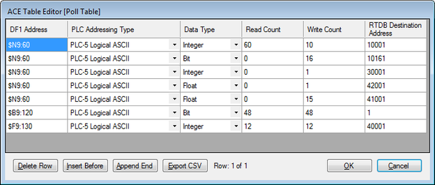
Example of Continuation Poll
As an example of a continuation poll, assume that the DF1 PLC has statuses, accumulators, controls, and setpoints all packed into different boards located at $N9:60 through $N9:119 registers (using PLC-5 Logical ASCII format). Below is an example poll table with this information.
Polling registers that do not exist
You must have data in the registers that you are polling, otherwise you receive errors on that poll record during that poll attempt. For example, there are only 2 $F8 registers declared in this PLC program:
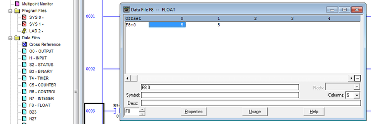
Attempting to poll register $F8:2 will result in an error.
Row 1 in the Poll table is the only row of the "continuation poll" that should be included in the Scan Table of the Master Channel (not rows 2-5). Rows 2-5 have the same DF1 Address and a Read Count of 0, indicating that these are continuation rows, used for parsing additional fields of data from the poll defined in Row 1. Following is additional explanation for each row in the Poll Table.
| Row | Description |
|---|---|
| Row 1 | Read 60 continuous 16-bit integer register values from the PLC, starting at address $N9:60 (this equates to polling for registers $N9:60 – $N9:119). Store the first 10 integer registers ($N9:60 – $N9:69) as Boolean status values starting at RTDB register 10,001. Each bit of each register is stored beginning with the least-significant bit, filling RTDB registers 10,001 – 10,160. |
| Row 2 | (continuation) Continue parsing through the 60 registers requested in the first Poll Table row. By using the "Bit" Data Type with a Write Count of 16, one additional 16-bit integer register ($N9:70) is parsed into RTDB registers 10,161 – 10,176. This shows than when using the "Bit" type, the count must be the number of bits, not integer registers. |
| Row 3 | (continuation) Store the next 16-bit integer ($N9:71) into register 30,001 in the RTDB. |
| Row 4 | continuation) Store the next two elements ($N9:72 – $N9:73) as a single 32-bit floating point number into 42,001 in the RTDB. Note that the number of elements parsed from the message is two, because the initial poll record used the Integer (16-bit) type. |
| Row 5 | (continuation) Store the next 30 elements ($N9:74 – $N9:103) as fifteen 32-bit integers into RTDB registers 41,001 – 41,030. (Note: The "Float" data type must be used for reading 32-bit integers into UINT32 or SINT32 RTDB registers because the DF1 Poll Table doesn't have an option for long integers. Long Integer data may only be read, not written.) (NOTE: Rows 1-5 define five continuation poll rows parsingonly 44 registers of 16-bit data ($N9:60 - $N9:103). The original poll record was for a count of 60, so the remaining 16 registers would be discarded. This is used for illustration but would not be an ideal configuration because it wastes communication bandwidth by polling for unused data. In an actual configuration, the first row's Read Count should be set to 44, or additional continuation rows should be defined.) |
| Row 6 | This is a new poll. Read 48 bits from the PLC (three 16-bit integer registers, $N9:120 - $N9:122) and store them as binary control values into RTDB registers 1 – 48. |
| Row 7 | This is a new poll. Read twelve 16-bit integer values from the PLC ($N9:130 – $N9:141) and store them as analog setpoints into RTDB registers 40,001 – 40,012. Note that the "DF1 Address" column uses "$F" – as noted above, the actual ASCII character used in this field is ignored by the RediGate. Ordinarily, this should set to "$N" for visual clarity, but the Data Type column determines how the data is actually parsed. |
Rows 6 and 7 of the Poll Table define a mapping of output registers in the PLC to Modbus register numbers in the RediGate's RTDB. This mapping works in both directions—data read from the PLC will be stored into the RTDB, and any values written to these RTDB registers will be written as control messages back to the PLC.
Rows 6 and 7 may be included as entries in the Master Channel's Scan Table, but only if the RediGate needs to read the binary control bits and analog setpoint values from the PLC continuously. If it is only necessary for a host system to write to these control registers (not read the feedback)—for instance, if the control feedback is obtained from reading other DF1 registers—the Poll Table definitions are still required in order to map Modbus RTDB registers to DF1 device point numbers, but there is no need to include Scan Table entries for these polls (see Master Channel on page ).
Modbus RTDB
See the RediGate Configuration Manual for information on configuring the RTDB.