Protocol_ROC
Screenshots May Differ from Current ACE Release
Many of these protocols were developed using the legacy ACE software, so the screenshots in the example may differ from what you will see in the current version of ACE. These differences are completely aesthetic, and all protocol functionality is supported regardless of the version of ACE you are using.
The user should be familiar with the Emerson document "ROC Plus Protocol Specifications Manual" (Form Number A6127) from October 2011, Part Number D301180X012.
The Poll Table should have the first set of rows reserved for Mapping Modbus Write commands to ROC Data areas with several rows (at least 20) unused for future changes. Then you can start configuring the Data Read OpCodes below the spare rows.
The first read is actually the Login Request and should be enabled when the RediGate is unable to communicate with the ROC RTU. The suggested technique to enable this poll requires the "Comms Status HoldReg" parameter being set to some input register like 30191. When the RTU is failed then 30191 will contain a "0" and when it is communicating it will contain a "7". If the "Skip Reg" column (not shown) is set to 30191 with the "Skip Condition" set to 'Skip if Equal to CONSTANT Value' and the 'Skip Value' set to "7" then the RediGate will attempt to Login whenever the Communications are failed.
The maximum ROC message packet size is 255 bytes. A 'rule of thumb' should be to not request more than 230 bytes of data in one transaction. If the 'Point Type' can potentially return more 230 bytes then two transactions should be used read the data in two parts.
Below is a capture of the most commonly used Poll Table Columns with a description of each column.

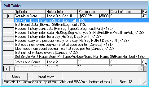
OpCode : There are several supported ROC OpCodes. When you click on the OpCode drop-down button you should be able to understand what the OpCode does and the Parameters required by it.
For instance, the highlighted OpCode for "Get Alarm Data" is attempting to inform the user that two parameters are required. The first parameter (#Alarms) is the number of Alarms to retrieve. You should set this value set to '1'. Even if you set it to a larger value the RediGate will only store the first record returned in the RTU response. The second parameter (StrtAlrmLogIndex) is actually a two byte value and is used as the Alarm Record Index to retrieve from the Alarm Log area. The value between the Less Than, Greater Than symbols "<>" is the actual value of the OpCode which in this case is 118.
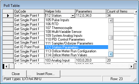
Helper Info: This column does not actually affect the poll packet but is instead intended to help the user remember the Point Numbers for different data Point Types as shown below. The top row displayed is used to configure reading the Station Parameters (112). The Single Point Read requires four parameters which are the Data Point Type (112), Logical Index (0), Count of Point Parameters (34) and starting Point Parameter (0). The "Parameters" column described next is where this information is supplied.
Parameters: The "Parameters" column is a 31 character field into which the user can simply type in Comma Separated Values (CSVs) to be used in a verbatim replacement into the Poll Packet or can be used to reference values stored in the RTDB which can be copied into the Poll Packet.
In the above capture the Poll Packet will be filled with the hex values of "70 00 22 00" as 112,0,34,0 is converted from decimal values.
If the user wants to copy data from the RTDB and place it into the Poll Packet then instead of using CSVs there is a second technique. This involves starting the string with the "@" symbol, followed by a starting Register address in the RTDB, then a COLON (:), then the Count of Registers followed by a Hyphen (-) and lastly an Element size per register ranging from 1 to 30. You should be able to place two of these @-Strings into the Parameters field.
An example of retrieving two registers from the RTDB for the Alam Log Data which requires the first parameter as a single byte and the second parameter as a two byte word would be "@50006:1-1 @50007:1-2". The contents of 50006 is placed first in the packet as a single byte followed by two bytes from 50007.
Another special feature uses the LESS THAN symbol (<) to instruct the protocol to use TLP information stored in the RTDB to determine what kind of information is to be associated with OpCode 10 (Get Configurable OpCode Table Values) and OpCode 11 (Put Configurable OpCode Table Values). For example if you read theTLPs for Point Type 99 (Table-0 to 15) into 30771 (as triplet values) then you can execute OpCode 10 (Get OpCode Table Values) and use Poll Table Parameters String "0,0,44 <30771" to know what kind of data to expect from Table 0, Table Location 0 for 44 Values.
Function Codes 10 (Read Configurable OpCode Point Data) and 11 (Write Configurable OpCode Point Data) use a special additional String Parameter which should follow the Table-Number, Starting-Table-Location, Number-of-Table-Locations string. The additional string begins with the Less Than Symbol (<) followed by the 5 digit RTDB Register starting address containing the T-L-Ps definitions configured by Point-Type 99 (Configurable OpCode Table). This will instruct the RediGate as to what type of date is being returned (UINT8, UINT16, UINT32, IEEE, DOUBLE, Char-String-32) or written.
If the "Parameters" column is not to be used then place a single "X' in the Parameters field.
You can enter "CSVs" and "@Strings|]" into the same Parameters field.
Count of Items: This will limit how much data is retrieved from a Poll Reply or it can be used to determine how many Modbus RTDB registers are associated with Write Commands.
RTDB REAL32s : This column configures the starting RTDB REAL32 register address associated with the ROC OpCode. When used with a 'Get' command this configures where to begin storing Floating Point data from the ROC Reply in the RediGate's RTDB area. If the other three RTDB column fields for this row are set to zero then all data items from the ROC Reply will be contained in a series of REAL32 registers.
For now it is best if this Column is not set to zero for any 'Get' command even if there is not any Floating point data expected in the ROC Reply. The data sorting logic is not as robust when the REAL32s field is set to zero.
When non-Floating point data is to be stored in the REAL32 area the following rules are used.
- A Single Byte Character value is first converted into the equivalent Floating Point number and then saved as a four byte IEEE value in the RTDB.
- A Two Byte Integer value is converted into the equivalent Floating Point number and then saved as a four byte IEEE value in the RTDB.
- A Character string is packed into four byte segments until no more characters are needed and stored into one or more IEEE RTDB registers.
- A Double float is stored in two separate IEEE RTDB registers.
RTDB Ints : This column configures the starting RTDB Integer register address associated with the ROC OpCode. When used with a 'Get' command this configures where to begin storing Integer data from the ROC Reply in the RediGate's RTDB area. Single byte Character data and two byte Short integers or 3 byte TLP information or four byte Long integers are all defined to be classified as Ints. TLP information is saved as three consecutive Integer registers. If the other three RTDB column fields for this row are set to zero then all data items from the ROC Reply will be contained in a series of Int16 registers.
When non-Int16 data is to be stored in the INT16 area the following rules are used.
- A Single Byte Character value is first converted into the a Int16 value and then saved as a two byte Int16 value in the RTDB.
- A Three Byte T-L-P value is saved as three consecutive Int16 RTDB registers.
- A Character string is packed into two byte segments until no more characters are needed and stored into one or more Int16 RTDB registers.
- A Double float is stored in four separate Int16 RTDB registers.
RTDB Char-32 : This column configures the starting RTDB 32 byte Character String register address associated with the ROC OpCode. When used with a ‘Get’ command this configures where to begin storing String data from the ROC Reply in the Director’s RTDB area. No other data type is allowed to be packed into this storage area.
RTDB REAL64s : This column configures the starting RTDB Double Float register address associated with the ROC OpCode. When used with a ‘Get’ command this configures where to begin storing Double Float data from the ROC Reply in the Director’s RTDB area. No other data type is allowed to be packed into this storage area.
Below are the remaining Poll Table Columns.
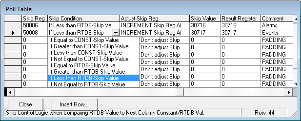
Skip Reg : When this is set to a non-zero value then one or more actions can be applied to the execution of the poll record. Firstly the Poll Record can be skipped when the ‘Skip Condition’ logic is examinded to be TRUE. There are four conditions that can be selected when comparing the ‘Skip Reg’ value from the RTDB to the ‘Skip Value’. The conditions are being Equal to, Greater Than, Less Than or Not Equal to the Skip Value. The ‘Skip Value’ is either interpreted as a CONSTANT or as a reference to a register in the RTDB area.
Skip Condition : Used in conjunction with the ‘Skip Reg’ and ‘Skip Value’.
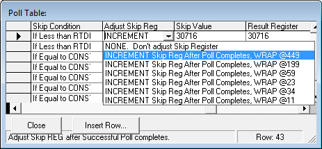
Adjust Skip Reg : Upon successfully completing this poll record (not skipping it) then this option will allow the Director to increment the value referenced in the ‘Skip Reg’ field. If desired the ‘Skip Reg’ will be incremented after each successful poll until it is wrapped back to zero once it reaches 450, 200, 59, 23, 34 or 11.
Skip Value : This is either used as a verbatim constant value or as a reference to an register in the RTDB area.
Result Register : If set to a non-zero value then the number of bytes received from this poll record will be saved to the RTDB.
Comment : A generic twenty-three character comment field.
Supported ROC Function Codes
6 - Get System Config (Save to a series of 214 Integer Registers) Does not skip any received bytes.
7 - Get ROC Time (Save to a series of 7 Integer Registers) Sec,Min,Hour,Day,Month,Year,DOW. Does not skip over any received bytes.
8 - Set ROC Time (Write from a series of 6 Integer Registers) Sec,Min,Hour,Day,Month,Year. Does not skip over any received bytes.
10 – Get ROC Configurable OpCode Point Data. First the user should save the TLP information for Point Type 99 into the RTDB area. Then using the Parameters Column by adding the “<RTDB-REG” string the protocol will know how to parse the data from this reply. Skips over THREE received bytes, TABLE-NUMBER,, STARTING-TABLE-LOCATION, NUMBER-OF-TABLE-LOCATIONS. The String Parameters column might contain the following -à “0,17,8 <30505” which will be interpreted as Table-0, Starting Table Position 17 for eight consecutive elements and retrieve the TLP definitions from the RTDB at 30505.
17 - Request to Login (Write a 3 Char User-ID, INT16-Password(2 bytes), [User-Level(1 byte)]). Does not skip over any received bytes.
Poll Table Parameters should be something like… ABC 9876 …or… ABC 9876 0 for User ID, Password and optional User Entry Level.
24 - Store and Forward (Automatically implemented if Hop Information non-zero). Automatically implemented if the ‘1st Dest Station’ and the ‘1st Dest Group’ are non-zero.
50 - Get I/O Point Information (Save to a series of 160, 240 or 224 Integer Registers). Parameter set to either “0” for I/O Point Type or “1” for I/O Logical Number. Does not skip over any received bytes.
108 - Get History Segment Tag(s) and Record Index (Save Newest Record Index, up to 20 pairs of Point Number and ASC-10 strings) Required History Index(1 byte), Count of Points(1 byte) and Point-Numbers(1 byte each). For example to read the first 5 Point Tag Names from the 9th History Segment the Parameters would be “9,5,0,1,2,3,4” as comma separated string elements. Skips over TWO received byte, HISTORY-SEGMENT-NUMBER, NUMBER-OF-HISTORICAL-POINTS.
118 - Get Alarm Log Record (Requires Number of Records (1 byte), Starting Record Index(2 bytes)) (Save to either series of Integers or break down into Integers, Float and String). To be a dynamically changing poll then you would probably use the Parameters like “@50005:1-1 @50006:1-2”. In this case the RTDB register 50005 would contain the maximum number of records to request (only 1 at a time supported) and 50006 would contain the Starting Record to read as a two byte value. This poll will also probably require the Skip Register with Auto Increment and lastly implementing the “Result Register”. The values would be “50006”, “If Less than RTDB-Skip Value”, “INCREMENT Skip Reg After Poll Completes, Wrap @449”, “30716”, and “30716”. Then if your force 30716 with a Custom Report, or IsaGraf, or a POD routine to “0” the poll will execute, save the receive byte count when successful, increment the contents to 50006 and wrap it back to zero when it reaches 450. Does not skip over any received bytes.
119 - Get Event Log Record (Requires Number of Records(1 byte), Starting Record Index(2 bytes) (Save to either series of Integers or break down into Integers, Float and String) Same technique as Get Alarm Log above. Does not skip over any received bytes.
139 – Get History Information Data Requires at least 9 bytes of String Parameters (Support MORE_PARAMETERS_OPCODE). The first byte is the Sub-Command which should be a ‘1’. The second byte is the History Segment number ranging from 0 to 11. The third-fourth byte pair are the ‘History Segment Index’ ranging from 0 to the number of configured Items in history. The fifth byte is the Type of History (0=Minute, 1=Periodic, 2=Daily). The sixth byte is the number of ‘Time Periods’ but will internally be forced to a ‘1’ regardless of this entry. The seventh byte is ‘Request Time Stamps’ option and is either a ‘0’ or a ‘1’. The eighth byte is the ‘Number of Points’ being requested. The ninth (and any succeeding bytes) are the Point Number(s) to be requested from the History Segment. (( I might add another optional String parameter “<<” to indicate that the _abParseDefs[] array will be retrieved from the RTDB )). Currently this OpCode assumes that only REAL32 floating point data is being read from the History Segment.
180 – Get Specific (Random) Parameters is only to be used for reading TLP (Parameter 02) information from History Segments 00 to 11 (Point Types 125 to 135). (It supports the MORE_PARAMETERS OpCode selection.) This information will be used by OpCode 139 above in the FUTURE. The first Parameter String byte is the number of History Segment parameters to be requested. Then groups of three bytes will be used as to which T-L-Ps to read where the ‘T’ can only range from 125 to 135 to access History Segments 00 to 11. The ‘L’ is the logic index of the History Element from 0 to 240. Lastly the Parameter byte must always be set to a ‘2’ which selects the Source Data TLP. The first byte of the ROC reply, NUMBER_OF_PARAMETERS_REQUESTED, will be skipped and also the first three bytes of the groups of six bytes. The second three bytes of the group of six bytes will be the requested History Point Source TLP information.
166 - Set Single Point Contiguous Parameter(s) (Requires Point Type Number (1 byte), Logical Index(1 byte), Number of Parameters(1 byte), Starting Parameters (1 byte)). (Write from either a series of Integer Registers or break down into Floats, Integers, Char-32-String, Double-Floats). Does not skip over any received bytes.
167 - Get Single Point Contiguous Parameter(s) (Requries Point Type Number (1 byte), Logical Index(1 byte), Number of Parameters(1 byte), Starting Parameters (1 byte)). (Save to either a series of Integer Registers or break down into Floats, Integers, Char-32-String, Double-Floats). Skips over FOUR received bytes, POINT-TYPE, LOGICAL-NUMBER, NUMBER-OF-PARAMETERS, STARTING-PARAMETER-NUMBER.
256 – CONTINUE for More String Parameters allows more than one row of String Parameters to be constructed for one OpCode.
ROC Point Types Supported, July 9, 2013
82 – Virtual Discrete outputs. For example will require 8 REAL32, 20 INT16s and 2 STRING-32 RTDB registers to read entire set of Parameters for a Logical Index.
91 – System Variables. For example will require 2 REAL32s, 61 INT16s and 8 STRING-32 Rtdb registers to read the entire set of Parameters for a Logical Index.
99 – Configurable OpCode Table TLPs. For example will require 132 INT16s and 1 STRING-32 Rtdb registers to read the entire set of Parameters for a Logical Index.
101 – Discrete Inputs. For example will require 5 REAL32s, 10 INT16s and one STRING-32 Rtdb registers to read the entire set of Parameters for a Logical Index.
102 – Discrete Outputs. For example will require 8 REAL32s, 18 INT16s and 2 STRING-32 Rtdb registers to read the entire set of Parameters for a Logical Index.
103 – Analog Inputs. For example will require 20 REAL32s, 18 INT16s and 2 STRING-32 Rtdb registers to read the entire set of Parameters for a Logical Index.
104 – Analog Outputs. For example will require 6 REAL32s, 9 INT16s and 2 STRING-32 Rtdb registers to read the entire set of Parameters for a Logical Index.
105 – Pulse Inputs. For example will require 15 REAL32s, 13 INT16s and 2 STRING-32 Rtdb registers to read the entire set of Parameters for a Logical Index.
106 – RTD Inputs. For example will require 18 REAL32s, 18 INT16s and 2 STRING-32 Rtdb registers to read the entire set of Parameters for a Logical Index.
107 – Thermocouple Inputs. For example will require 10 REAL32s, 9 INT16s and 2 STRING-32 Rtdb registers to read the entire set of Parameters for a Logical Index.
108 – Multi-Variable Sensors. For example will require 40 REAL32s, 26 INT16s and 1 STRING-32 Rtdb registers to read the entire set of Parameters for a Logical Index.
109 – System Analog Inputs. For example will require 11 REAL32s, 12 INT16s and 2 STRING-32 Rtdb registers to read the entire set of Parameters for a Logical Index.
110 – PID Controls 0-15. For example will require 30 REAL32s, 45 INT16s and 1 STRING-32 Rtdb registers to read the entire set of Parameters for a Logical Index.
111 – Sampler/Odorizer 0-9. For example will require 3 REAL32s, 8 INT16s and 0 STRING-32 Rtdb registers to read the entire set of Parameters for a Logical Index.
112 – Station Parameters. For example will require 51 REAL32s, 17 INT16s and 1 STRING-32 Rtdb registers to read the entire set of Parameters for a Logical Index.
113 – Orifice Meter Configuration. For example will require 16 REAL32s, 27 INT16s and 2 STRING-32 Rtdb registers to read the entire set of Parameters for a Logical Index.
114 – Orifice Meter Live Values. 36 Real32s, 0 UINT16s, 0 STRING-32, 4 Real64s
115 – Turbine Meter Configuration. 36 Real32s, 1 UINT32, 20 UINT16s, and 2 STRING-32
116 – Turbine Meter Live Values. 40 Real32s, 5 Real64s, 1 UINT32, 0 all others
124 – History Segment Configuration. 1 STRING-32, 1 UINT32, 11 INT16s, and 0 others.
125 – History Segment-00 Point Configuration. 2 STRING 32s, 6 Real32s, 4 UINT32s, 5 UINT16s.
126 – History Segment-01 Point Configuration. Ditto.
127 – History Segment-02 Point Configuration. Ditto.
128 – History Segment-03 Point Configuration. Ditto.
129 – History Segment-04 Point Configuration. Ditto.
130 – History Segment-05 Point Configuration. Ditto.
131 – History Segment-06 Point Configuration. Ditto.
132 – History Segment-07 Point Configuration. Ditto.
133 – History Segment-08 Point Configuration. Ditto.
134 – History Segment-09 Point Configuration. Ditto.
135 – History Segment-10 Point Configuration. Ditto.
136 – ROC Clock. 8 UINT16s, 2 UINT32s.
139 – (Not Tested Yet) Smart I/O Information. 9 STRING-32s, 3 INT16s.
142 – History Segment-11 Point Configuration
143 – History Segment-12 Point Configuration
BROADCAST
To support broadcast you might be able to create an extra Field Unit object that has the proper broadcast parameters (Station-Address and Group-Code) and attempt to write to this RTU for broadcasting writeable information.