...
| Expand | ||||||
|---|---|---|---|---|---|---|
| ||||||
|
| Anchor | ||||
|---|---|---|---|---|
|
...
| EVDO modem | Internal EVDO cellular modem (Verizon) |
| GSM modem | Internal GSM/HSPA cellular modem (AT&T, Telus) |
| 4 COM ports | Additional RS232 and RS485/422 serial ports (total of 6 RS232, 2 RS485) |
| Multi-I/O | Internal I/O expansion board, providing 16 AI, 2 AO, and 8 DI |
| Relay8/IN8 | Internal I/O expansion board, providing 8 DI and 8 relay outputs |
Please contact Elecsys to obtain pricing for a particular configuration of optional equipment or software. The table below gives model numbers for several standard part numbers of the base RediGate plus combinations of optional features. All models typically use COM0 (RS-232) for the administrative console port.

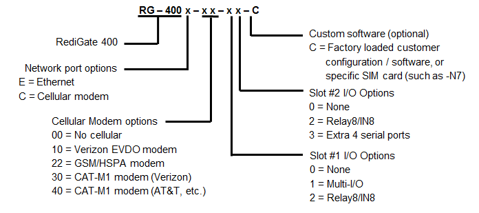
Examples:
RG-400E-00-00 Base RediGate 400 (4 Ethernet, 3 RS-232, 1 RS-485/422)
RG-400C-40-00 RediGate 400 + CAT-M1 modem (physical SIM slot for AT&T or other)
See RediGate Product Comparison and Selection Guide for a list of part numbers, features, and accessories.
Specifications
Enclosure / Dimensions
...
Model | RediGate 400 |
Width | 6.92" (175.77 mm) |
Depth | 6.78" (172.21 mm) |
Height | 2.61" (66.29 mm) |
Weight | 2.5 lbs (1.13 kg) |
...
Dimensions
The mechanical and mounting dimensions of the RediGate are shown below (all dimensions in inches).
Top

Bottom

Front

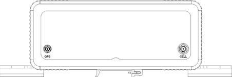
Rear (cellular model)
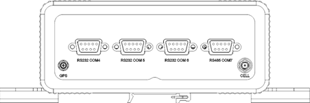
Rear (cellular model w/ serial expansion ports)
Mounting Instructions
The RediGate is intended to be installed in a Restricted Access Location. When mounting the RediGate, allow sufficient space to connect the cables on the front and rear of the enclosure, depending on any optional hardware components installed. There are two recommended means of mounting the device: panel mount, or DIN rail mount.
...
Pin | RS-485 Name | Type | Description | ||
|---|---|---|---|---|---|
1 | NC |
|
| ||
2 | NC |
|
| ||
3 | TX- | Output | Transmit Data - | ||
4 | RX- | Input | Receive Data - | ||
5 | GND | Common | Ground | ||
6 | NC |
|
| ||
7 | TX+ | Output | Transmit Data + | ||
8 | RX+ | Input | Receive Data + | ||
9 | NC |
|
|
RS-485/422 Wiring Diagrams
...
In the United States, the antenna should support the 850 MHz and 1900 MHz frequency bands. In other countries, check to make sure what GSM frequencies are used in order to select the correct antenna.
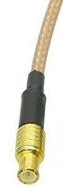
Cellular antenna: The cellular connector requires an antenna with a standard male SMA plug and 50 ohm cable, with a minimum cable length of 20 cm and maximum gain (including cable loss) as follows:
...
GPS antenna: The GPS connector requires an antenna with a standard male MCX plug and 50 ohm cable with frequency 1575.42 MHz. The use of an active GPS antenna may achieve better performance, especially when the GPS antenna distance from the device is large.
Installing SIM Card
| Include Page | ||||
|---|---|---|---|---|
|
...
Certain models of RediGate provide an analog/digital module, allowing the RediGate to be used for data acquisition from up to 16 analog inputs, 8 digital inputs, and 2 analog outputs. The Multi-I/O module (Eurotech model AIM104-MULTI I/O) is factory installed inside the RediGate. A 50-way 'D' type connector allows connection to the field signals using an external screw termination block.
Multi-I/O Specifications
...
Power Consumption | 2.4 Watts, excluding loop power |
| Link setting | |
|---|---|
Analog Mode | 16 channel AI single-ended (LK3 fitted, LK4-A) |
Board #1 address | LK1 jumpers: A2, A3, A4, A6 [0x3A0] |
| Board #2 address | LK1 jumpers: A3, A4, A6 [0x3A4] |
...
Function (MULTI-I/O) | 50-way 'D' pin (enclosure) | 50-way screw termination | |||
Digital Inputs |
|
| |||
|---|---|---|---|---|---|
DI Common | 1 | 1 | |||
DI 1 | 2 | 34 | |||
DI 2 | 3 | 18 | |||
DI 3 | 4 | 2 | |||
DI 4 | 5 | 35 | |||
DI 5 | 6 | 19 | |||
DI 6 | 7 | 3 | |||
DI 7 | 8 | 36 | |||
DI 8 | 9 | 20 | |||
DI Common | 10 | 4 | |||
Analog Inputs |
|
| |||
AI Common | 20 | 40 | |||
AI 1 | 12 | 21 | |||
AI 2 | 13 | 5 | |||
AI 3 | 14 | 38 | |||
AI 4 | 15 | 22 | |||
AI 5 | 16 | 6 | |||
AI 6 | 17 | 39 | |||
AI 7 | 18 | 23 | |||
AI 8 | 19 | 7 | |||
AI 9 | 22 | 8 | |||
AI 10 | 23 | 41 | |||
AI 11 | 24 | 25 | |||
AI 12 | 25 | 9 | |||
AI 13 | 26 | 42 | |||
AI 14 | 27 | 26 | |||
AI 15 | 28 | 10 | |||
AI 16 | 29 | 43 | |||
AI Common | 30 | 27 | |||
Analog Outputs |
| ||||
Current output: |
|
| |||
AO 1 Current Loop | 34 | 12 | |||
AO 1 Current Return | 36 | 29 | |||
AO 2 Current Loop | 38 | 46 | |||
AO 2 Current Return | 40 | 14 | |||
Voltage output: |
|
| |||
AO 1 Vout | 43 | 15 | |||
CGND | 35 | 45 | |||
AO 2 Vout | 44 | 48 | |||
CGND | 39 | 30 |
|
|
|
(unused CGND pins) | 11, 21, 31 | 37, 24, 11 | |||
(not connected) | 32, 33, 37, 41, 42, 45, 46, 47, 48, 49, 50 | 44, 28, 13, 47, 31, 32, 16, 49, 33, 17, 50 |
Some typical wiring diagrams are shown below. Ensure that connections are made to the appropriate termination number for each input or output type, and that the configuration is set correctly for the board number and analog input type (see Multi-I/OSoftwareAccess720903). 


Multi-I/O Software Access
To read the analog or digital inputs and write to the analog outputs, use either ACE-defined POD logic ("PC-104 MULTI-IO-se" function) or an ISaGRAF program (include the "AIMMLTIO" board). In either case, the board parameters should include the Board Address (see MULTI-I/OBoard 720903), and the data should be made available in appropriate RTDB addresses.
...
Relay8/IN8 Specifications
...
Power Consumption | 1.25 Watts, excluding loop power |
| Link Settings | |
|---|---|
Board #1 address | LK1 jumpers: A2, A3, A4, A7 [0x360] |
Board #2 address | LK1 jumpers: A3, A4, A7 [0x364] |
| Input filter (de-bounce) | LK2A-H fitted |
...
Function (RELAY8/IN8) | 50-way 'D' (enclosure) | 50-way screw termination | ||
Digital Inputs |
|
| ||
|---|---|---|---|---|
DI Common | 1 | 1 | ||
DI 1 | 2 | 34 | ||
DI 2 | 3 | 18 | ||
DI 3 | 4 | 2 | ||
DI 4 | 5 | 35 | ||
DI 5 | 6 | 19 | ||
DI 6 | 7 | 3 | ||
DI 7 | 8 | 36 | ||
DI 8 | 9 | 20 | ||
DI Common | 10 | 4 | ||
Digital Outputs |
|
| ||
Relay 1 Common | 12 | 21 | ||
Relay 1 Normally Open | 13 | 5 | ||
Relay 1 Normally Closed | 14 | 38 | ||
Relay 2 Common | 17 | 39 | ||
Relay 2 Normally Open | 18 | 23 | ||
Relay 2 Normally Closed | 19 | 7 | ||
Relay 3 Common | 22 | 8 | ||
Relay 3 Normally Open | 23 | 41 | ||
Relay 3 Normally Closed | 24 | 25 | ||
Relay 4 Common | 27 | 26 | ||
Relay 4 Normally Open | 28 | 10 | ||
Relay 4 Normally Closed | 29 | 43 | ||
Relay 5 Common | 32 | 44 | ||
Relay 5 Normally Open | 33 | 28 | ||
Relay 5 Normally Closed | 34 | 12 | ||
Relay 6 Common | 37 | 13 | ||
Relay 6 Normally Open | 38 | 46 | ||
Relay 6 Normally Closed | 39 | 30 | ||
Relay 7 Common | 42 | 31 | ||
Relay 7 Normally Open | 43 | 15 | ||
Relay 7 Normally Closed | 44 | 48 | ||
Relay 8 Common | 47 | 49 | ||
Relay 8 Normally Open | 48 | 33 | ||
Relay 8 Normally Closed | 49 | 17 |
|
|
(not connected) | 11, 15, 16, 20, 21, 25, 26, 30, 31, 35, 36, 40, 41, 45, 46, 50 | 37, 22, 6, 40, 24, 9, 42, 27, 11, 45, 29, 14, 47, 32, 16, 50 |
Some typical wiring diagrams are shown below. Ensure that connections are made to the appropriate termination number for each input or output type, and that the configuration is set correctly for the board number and analog input type (see Relay8/IN8SoftwareAccess 720903). 
Relay8/IN8 Software Access
...
The following screen captures are an example of the I/O connection in ISaGRAF when using the Relay8/IN8 board. Digital input and output values are stored in the ISaGRAF RTU and must be polled into an RTDB using the Internal Channel configuration, so that data can be made available to other systems.

