RediGate 400 Hardware Manual
- Jon Tandy
- Former user (Deleted)
- Jon Tandy (Deactivated)
- Former user (Deleted)

Product Information
Full information about other Elecsys products is available on our website at www.elecsyscorp.com and the RediGate Product Support page.
Product Support
Tel: +1-913-890-8905
Fax: +1-913-982-5766
Email: idc-support@elecsyscorp.com
Headquarters, Sales, Support & Manufacturing
Elecsys Corporation
846 N Mart-Way Court
Olathe, KS 66061
Tel: +1-913-647-0158
Fax: +1-913-982-5766
Email: info@elecsyscorp.com
While Elecsys may assist customers with their choice of products, the final choice of product for a specific application is entirely the responsibility of the buyer. Elecsys' entire liability with respect to its products or systems is defined in the Elecsys standard terms and conditions of sale.
Any example code is provided only to illustrate the use of Elecsys products. No warranty, either expressed or implied, is made regarding any example code provided by Elecsys and Elecsys shall incur no liability whatsoever arising from any use made of this code.
Disclaimers
The information in this manual is believed to be accurate at the time of publication. Elecsys Corporation assumes no responsibility for inaccuracies that may be contained in this document and makes no commitment to update or keep current the information contained in this manual. Elecsys Corporation assumes no responsibility for any infringements of patents or other rights of third parties that may result from its use. Elecsys Corporation reserves the right to make changes or improvements to this document and/or product at any time and without notice. While Elecsys may assist customers with their choice of products, the final choice of product for a specific application is entirely the responsibility of the buyer. Elecsys' entire liability with respect to its products or systems is defined in the Elecsys standard terms and conditions of sale.
Any example code is provided only to illustrate the use of Elecsys products. No warranty, either expressed or implied, is made regarding any example code provided by Elecsys and Elecsys shall incur no liability whatsoever arising from any use made of this code.
Electrostatic Discharge (ESD) Protection
These units contain devices that could be damaged by the discharge of static electricity. At all times, please observe industry standard ESD precautions when handling the unit.
![]() WARNING: DO NOT CONNECT OR DISCONNECT CABLES WHEN ENERGIZED, UNLESS POWER HAS BEEN REMOVED FROM THE EQUIPMENT OR THE AREA IS KNOWN TO BE FREE OF IGNITABLE CONCENTRATIONS OF FLAMMABLE SUBSTANCES.
WARNING: DO NOT CONNECT OR DISCONNECT CABLES WHEN ENERGIZED, UNLESS POWER HAS BEEN REMOVED FROM THE EQUIPMENT OR THE AREA IS KNOWN TO BE FREE OF IGNITABLE CONCENTRATIONS OF FLAMMABLE SUBSTANCES.
© 2024 Elecsys Corporation
Table of Contents
Preface
Scope of this Manual
This manual describes the standard hardware configuration of the Elecsys RediGate 400 Series Industrial Data Gateway and optional hardware.
Electromagnetic Compatibility (EMC)
The RediGate is classified as a component with regard to FCC EMC regulations, and it is the user's responsibility to ensure that systems using the product are compliant with the appropriate EMC standards.
This equipment has been tested and found to comply with the limits for a Class A digital device, pursuant to part 15 of the FCC Rules. These limits are designed to provide reasonable protection against harmful interference when the equipment is operated in a commercial environment. This equipment generates, uses, and can radiate radio frequency energy and, if not installed and used in accordance with the instruction manual, may cause harmful interference to radio communications. Operation of this equipment in a residential area is likely to cause harmful interference in which case the user will be required to correct the interference at his own expense.
Radio Frequency Requirements
This device complies with Part 15 of FCC Rules. Operation is subject to the following two conditions:
- This device may not cause harmful interference.
- This device must accept any interference received, including interference that may cause undesired operation.
- To comply with RF safety requirements, you must maintain a distance of 20 cm from the antenna when operating the device.
- Each antenna of this device must not be co-located within 20 cm of any other antenna or transmitter. Antenna requirements are listed in Cellular and GPS Antennas on page .
The RediGate 400 may be supplied with an EVDO cellular module (FCC ID: RI7DE910-DUAL), or with a GSM cellular module (FCC ID: RI7HE910).
Changes or modifications to the product not expressly approved by Elecsys Corporation could void the user's authority to operate the equipment.
Introduction
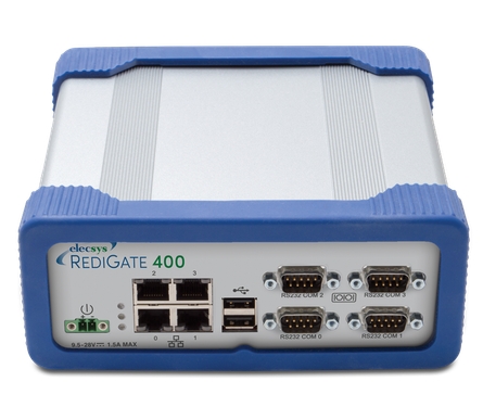
The RediGate is a ruggedized field proven edge-of-network front end processor designed for industrial field applications. This single device enables a seamless migration path for quicker data acquisition, automatic communication failover, cyber security, bandwidth management, and protocol conversion throughout your entire industrial communication network.
With a wide selection of industry standard and legacy protocols, the RediGate can gather data from almost any field device and deliver it to your enterprise data systems. Combining our Advanced Configuration Environment (ACE) with one of the industry's best application programming languages (ISaGRAF), the RediGate can be easily programmed for most applications.
The RediGate 400 Series has an optional integrated cellular modem and also supports I/O expansion options enabling the unit to be easily customized for your specific application. Utilizing its native MQTT client, the RediGate directly interfaces with messaging middleware/data brokers, new and legacy SCADA hosts, ERP systems, Leak Detection, Maintenance Systems and other enterprise applications. Elecsys also provides the "HCP2" (host communication processer) and OPC software packages to enhance the performance and capabilities of your existing system.
This manual provides information describing the hardware for the Elecsys RediGate 400 Series Industrial Data Gateway. It details the standard and optional hardware components, technical specifications, and other hardware information that may be needed to configure the device. The RediGate is based upon a Linux based operating system.
All circuit boards are mounted in a rugged metal enclosure. RediGate units are shipped fully tested and may be pre-loaded with customer-specific configurations prior to shipment.
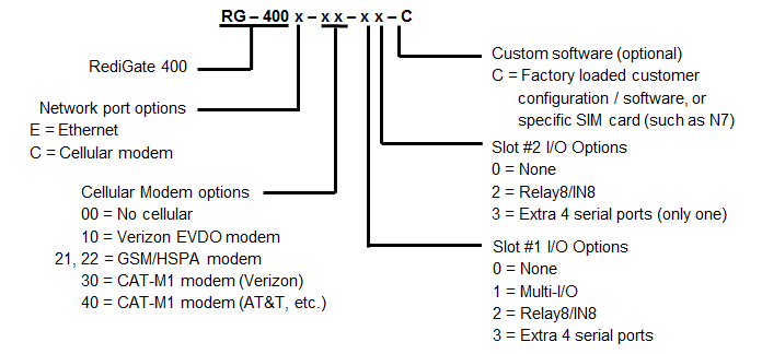
RediGate 400 Model Options
The RediGate 400 Series Gateways have a variety of hardware and software options depending on the model chosen. Some of these optional features are described below:
| EVDO modem | Internal EVDO cellular modem (Verizon) |
| GSM modem | Internal GSM/HSPA cellular modem (AT&T, Telus) |
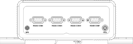
| 4 COM ports | Additional RS232 and RS485/422 serial ports (total of 6 RS232, 2 RS485) |
| Multi-I/O | Internal I/O expansion board, providing 16 AI, 2 AO, and 8 DI |
| Relay8/IN8 | Internal I/O expansion board, providing 8 DI and 8 relay outputs |
Please contact Elecsys to obtain pricing for a particular configuration of optional equipment or software. The table below gives model numbers for several standard part numbers of the base RediGate plus combinations of optional features. All models typically use COM0 (RS-232) for the administrative console port.
Examples:
RG-400E-00-00 Base RediGate 400 (4 Ethernet, 3 RS-232, 1 RS-485/422)
RG-400C-40-00 RediGate 400 + CAT-M1 modem (physical SIM slot for AT&T or other)
See RediGate Product Comparison and Selection Guide for a list of part numbers, features, and accessories.
Specifications
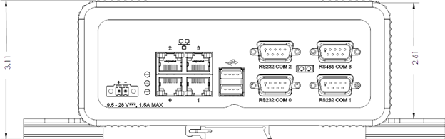
Enclosure / Dimensions
Model | RediGate 400 |
Width | 6.92" (175.77 mm) |
Depth | 6.78" (172.21 mm) |
Height | 2.61" (66.29 mm) |
Weight | 2.5 lbs (1.13 kg) |
Dimensions
The mechanical and mounting dimensions of the RediGate are shown below (all dimensions in inches).
Top

Bottom

Front
Rear (cellular model)
Rear (cellular model w/ serial expansion ports)
Mounting Instructions
The RediGate is intended to be installed in a Restricted Access Location. When mounting the RediGate, allow sufficient space to connect the cables on the front and rear of the enclosure, depending on any optional hardware components installed. There are two recommended means of mounting the device: panel mount, or DIN rail mount.
For panel mounting the RediGate, use four screws of an appropriate size and type to securely attach the enclosure to a customer-supplied panel or enclosure, using the four keyhole slots on the sides of the mounting plate bracket shown in the dimensional diagrams in the previous section. Connect all the I/O cables, and lastly attach the power connector to the RediGate.
The RediGate are optionally supplied with two (2) DIN rail clamps (shown on the bottom view dimensional drawing in the previous section). The DIN rail clamps allow mounting either vertically or horizontally. To mount the RediGate to DIN rail, use the following instructions:
- Determine the correct location and orientation of the RediGate that will accommodate all attached cables and connectors.
- Install a piece of DIN rail (35mm top hat rail) to the mounting location using appropriate screws or bolts. DIN rail should be installed horizontally, and should be a minimum of 5 in. (127mm) for mounting the RediGate in the vertical orientation, or a minimum of 10 in. (254 mm) for mounting in the horizontal orientation.
- Detach the mounting plate bracket from the RediGate by removing the four screws.
- On the other side of the mounting plate bracket (the side touching the RediGate enclosure) there are eight countersunk screw holes. Only four of these screw holes will be used, depending on the intended mounting orientation of the RediGate.
Using the four supplied DIN rail clamp screws (M4, 6mm), attach the two DIN rail clamps to the mounting plate in either the horizontal or vertical orientation, as determined earlier.

Vertical orientation

Horizontal Orientation
- Reattach the mounting plate bracket to the RediGate using the original screws (8-32, 3/8 in).
- Hang the spring side of the RediGate's DIN rail clamps on the DIN rail and snap into place.
- Ensure that the mounting is secure, then connect all the I/O cables, and lastly attach the power connector to the RediGate.
Compliance with Hazardous Area Standards
The RediGate has approval for installation in Class I Division 2 Groups A, B, C and D Classified Hazardous Locations, temperature class T4. Class, Division, and Group are defined as:
- Class defines the general nature of the hazardous material in the surrounding atmosphere. Class I is for locations where flammable gases or vapors may be present in the air in quantities sufficient to produce explosive or ignitable mixtures.
- Division defines the probability of hazardous material being present in an ignitable concentration in the surrounding atmosphere. Division 1 locations are presumed to be hazardous. Division 2 locations are areas where gas, dust, or vapors can exist under abnormal conditions.
- Group defines the hazardous material in the surrounding atmosphere. Groups A to D are defined as follows:
- Group A – Atmosphere containing acetylene, gases or vapors of equivalent hazards.
- Group B – Atmosphere containing hydrogen, gases, or vapors of equivalent hazards.
- Group C – Atmosphere containing ethylene, gases, or vapors of equivalent hazards.
- Group D – Atmosphere containing propane, gases, or vapors of equivalent hazards.
For the RediGate to be approved for hazardous locations, it must be installed according to the National Electrical Code (NEC) Article 501 (or Canadian Electrical Code, Section 18), and any local code requirements, if applicable.
DO NOT CONNECT OR DISCONNECT CABLES WHEN ENERGIZED, UNLESS POWER HAS BEEN REMOVED FROM THE EQUIPMENT OR THE AREA IS KNOWN TO BE FREE OF IGNITABLE CONCENTRATIONS OF FLAMMABLE SUBSTANCES.
When installing units in a hazardous area, make sure all installation components selected are labeled for use in such areas. Installation and maintenance must be performed only when the area is known to be non-hazardous. Installation or maintenance in a hazardous area could result in personal injury or property damage.
The certificate for this equipment includes the following special conditions for safe use:
- Install the equipment in an IP54 or better enclosure or equivalent location. Any enclosure shall be suitably certified or otherwise approved for Class 1 Division 2 hazardous locations. This may include an instrumentation tray cable (Type ITC) or similar means of limiting access to connect or disconnect cables under hazardous conditions.
- Ensure that the rated input voltage is not exceeded in service.
- The USB ports should not be used in a hazardous location.
System Specifications
General Features:
Model: | RediGate 400 |
Memory: | RAM: 256MB |
Serial Ports: | 3x RS-232 (up to 6x with expansion) |
LAN: | 4x RJ45 10/100baseT |
USB Ports: | 2x USB 2.0 host ports |
 Power: The device is intended to be powered from a Certified Limited Power Source (LPS, as defined in standard 60950-1) or a Certified "Class 2" Power Source (as defined in NEC and CEC).
![]() WARNING: DO NOT CONNECT OR DISCONNECT CABLES WHEN ENERGIZED, UNLESS POWER HAS BEEN REMOVED FROM THE EQUIPMENT OR THE AREA IS KNOWN TO BE FREE OF IGNITABLE CONCENTRATIONS OF FLAMMABLE SUBSTANCES.
WARNING: DO NOT CONNECT OR DISCONNECT CABLES WHEN ENERGIZED, UNLESS POWER HAS BEEN REMOVED FROM THE EQUIPMENT OR THE AREA IS KNOWN TO BE FREE OF IGNITABLE CONCENTRATIONS OF FLAMMABLE SUBSTANCES.
Operational Voltage: | +9.5 to +28 V |
Overvoltage Protection: | +50 V |
Reverse Voltage Protection: | -28 V |
Operating Current @24V: | 121 mA |
Power Consumption: * | Nominal Max |
(Note, the protection circuit will clamp above about 28.5 V input, preventing the RediGate from running. Input must drop below 28 volts to unclamp and return to operation.)
Environmental Characteristics
Operating: | -40 to +75 °C |
Storage: | -40 to +125 °C |
Humidity: | 0% to 95% relative humidity (non-condensing) |
Base RediGate 400 Hardware
This section describes the standard hardware and provides the dimensions and technical specifications for the RediGate. RediGate units are shipped fully tested and are typically supplied containing a default software configuration. Certain units may be pre-loaded with customer-specific configurations prior to shipment.
The RediGate consists of the following hardware components:
- Enclosure – Metal housing that contains the circuit boards and provides mounting options
- Data I/O Ports – Ethernet and serial COM ports used for peripheral communications
- Power Input – Connection port for powering the unit
- Status LEDs – Indicates process operations and functionality
- Top – Flashes and increases speed as the system load increases
- Center – Flashes to indicate that the system software is operational (watchdog enabled)
- Bottom –
Ethernet Ports
The RediGate provides 10/100 Mbps Ethernet ports for network communications, labeled '0', '1', '2' and '3'. In Linux, these correspond to network interfaces 'eth0' through 'eth3', respectively. Each of the Ethernet interfaces must be configured using the Advanced Configuration Environment (ACE) software tool in order to function, either with a fixed IP address or dynamically assigned DHCP addressing. The ports should be configured to operate on different, non-overlapping IP addresses/subnets.
Ethernet ports do not provide Power over Ethernet (PoE) and should not be connected to an unregulated PoE device.
![]() Ethernet ports not suitable for direct connection to WAN unless an appropriate interface is provided, to ensure lightning surge protection.
Ethernet ports not suitable for direct connection to WAN unless an appropriate interface is provided, to ensure lightning surge protection.
![]() WARNING: DO NOT CONNECT OR DISCONNECT CABLES WHEN ENERGIZED, UNLESS POWER HAS BEEN REMOVED FROM THE EQUIPMENT OR THE AREA IS KNOWN TO BE FREE OF IGNITABLE CONCENTRATIONS OF FLAMMABLE SUBSTANCES.
WARNING: DO NOT CONNECT OR DISCONNECT CABLES WHEN ENERGIZED, UNLESS POWER HAS BEEN REMOVED FROM THE EQUIPMENT OR THE AREA IS KNOWN TO BE FREE OF IGNITABLE CONCENTRATIONS OF FLAMMABLE SUBSTANCES.
Serial Ports
The base RediGate comes equipped with four external serial ports (3 RS 232, 1 RS485/RS 422), with an option for four additional ports (total of 6 RS 232, 2 RS485/RS 422). These ports are intended for local configuration and programming and for connection to external field devices.
The serial ports are configured using the ACE software tool. The first serial port (COM0) is typically reserved for a serial diagnostics, configuration and maintenance port.
The built-in serial ports are identified in Linux as follows:
Port | Linux Device | Electrical Standard |
|---|---|---|
COM0 | /dev/ttyS0 | RS232 |
COM1 | /dev/acscomm1 | RS232 |
COM2 | /dev/acscomm2 | RS232 |
COM3 | /dev/acscomm3 | RS-485/422 |
COM4 | /dev/acscomm4 | RS232 |
COM5 | /dev/acscomm5 | RS232 |
COM6 | /dev/acscomm6 | RS232 |
COM7 | /dev/acscomm7 | RS-485/422 |
![]() WARNING: DO NOT CONNECT OR DISCONNECT CABLES WHEN ENERGIZED, UNLESS POWER HAS BEEN REMOVED FROM THE EQUIPMENT OR THE AREA IS KNOWN TO BE FREE OF IGNITABLE CONCENTRATIONS OF FLAMMABLE SUBSTANCES.
WARNING: DO NOT CONNECT OR DISCONNECT CABLES WHEN ENERGIZED, UNLESS POWER HAS BEEN REMOVED FROM THE EQUIPMENT OR THE AREA IS KNOWN TO BE FREE OF IGNITABLE CONCENTRATIONS OF FLAMMABLE SUBSTANCES.
RS-232 Serial Interfaces
The direction of data with respect to the RediGate serial interfaces is such that the RediGate acts as a DTE (Data Terminal Equipment) device. The pin-out of the DB-9 serial interface for the RediGate RS 232 ports is as follows: 
Pin | EIA-232 Name | Type | Description |
|---|---|---|---|
1 | DCD | Input | Data Carrier Detect |
2 | RXD | Input | Receive data |
3 | TXD | Output | Transmit data |
4 | DTR | Output | Data Terminal Ready |
5 | GND | Common | Ground |
6 | DSR | Input | Data Set Ready |
7 | RTS | Output | Request To Send |
8 | CTS | Input | Clear To Send |
9 | RI | Input | Ring Indicate |
When configuring the RS-232 ports using the ACE software tool, the Warm-up and Warm-down fields are optional parameters that can be used to enable hardware flow control. This may be required to control sending and/or receiving data through certain external devices such as modems. If hardware flow control is not required, both the Warm-up and Warm-down parameters should be set to "-1" to disable hardware flow control.
RS-485/RS-422 Serial Interfaces
The RediGate provides an external RS-485/422 port on COM3, and optionally on COM7.
Warm-up and Warm-down
When configuring the RS-485/422 ports using the ACE software tool, the Warm-up and Warm-down times must be set to “0”. This enables hardware flow control, which is required to control the internal RS-485 circuit.
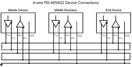
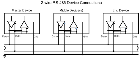
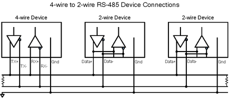
RS-485/422 uses an optically isolated, balanced differential system, in which the voltage produced by the driver appears across a pair of signal lines that transmit a single signal. A balanced line driver produces a voltage from 2 to 6 volts across its positive and negative output terminals. A balanced differential line receiver senses the voltage state of the transmission line across the two signal input lines. Up to 32 RS-485 devices or 10 RS-422 devices can be connected together in a multi-drop configuration.
The RediGate uses a four-wire serial interface for RS-485/422. The DB-9 pin-out is identified as follows:
Pin | RS-485 Name | Type | Description |
|---|---|---|---|
1 | NC | ||
2 | NC | ||
3 | TX- | Output | Transmit Data - |
4 | RX- | Input | Receive Data - |
5 | GND | Common | Ground |
6 | NC | ||
7 | TX+ | Output | Transmit Data + |
8 | RX+ | Input | Receive Data + |
9 | NC |
RS-485/422 Wiring Diagrams
When connecting RS-485 or RS-422 devices in a multi-drop configuration, there should typically be a 120 ohm termination resistor at both devices located at the ends of the network, but not on devices located in the middle of the network. This is used to balance the impedance in a long transmission line.
The RS-422 interface provides full-duplex communication. It supports one transmitter and up to 10 receivers.
The 4-wire RS-485 interface can provide either half-duplex or full-duplex communication. The interface supports up to 32 transmitters and receivers on a single network. Only one transmitter should be switched on at a time.
Some RS-485 devices use a 2-wire communication port instead of 4-wire. In order to connect the RediGate's RS-485 port to a 2-wire RS-485 device, connect the positive terminals (TX+ & RX+) to the positive terminal of the other device(s), and connect the RediGate's negative terminals (TX- & RX-) to the negative terminal of the other device(s). The 'customer' file must be set to ignore echo (see the RediGate Configuration Manual).
In RS-485 or RS-422 systems, the ground connection is required to properly establish the voltage reference for the differential voltages of the transmit and receive lines. The maximum end-to-end cable length for an RS-485/422 network is rated at 1200 m (4000 ft). Care should be taken in long runs to use twisted, shielded pair wiring to avoid the introduction of electromagnetic noise on the communication lines.
Typical RS-485 and RS-422 connections are shown in the following figure. Multi-drop networks are designed to be wired in a daisy-chain arrangement as shown, rather than a star arrangement (multiple nodes connected to a single point).
Real-time Clock
The RediGate includes a real-time clock, which may be used in some software features, such as system log files. There is no battery backup for the real-time clock, so if the clock is important to a particular application, the time must be synchronized after power-up to a network time server with Network Time Protocol (NTP). NTP may be configured using the ACE configuration software.
Optional RediGate 400 Hardware
Certain models of RediGate provide for optional hardware components. These optional components include:
- Additional Serial Ports – Additional four serial ports (3 RS-232, 1 RS-485).
- Cellular Modem – An EVDO or GSM/HSPA modem for cellular network connection
- Multi-I/O – I/O module providing 8 digital inputs, 16 analog inputs, and 2 analog outputs
- Relay8/IN8 – I/O module providing 8 digital inputs and 8 Form C relay outputs
Serial Port Expansion
The RediGate may be supplied with an optional 4 serial ports.
Cellular Modem
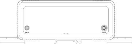
Certain models of RediGate provide a modem for cellular network communications. Only one modem may be used, depending on the chosen type of wireless technology. The modem is factory installed in the RediGate, and external antenna jacks allow connection to cellular (SMA) and GPS (MCX) antennas.
The EVDO socket modem card is based on the Telit DE910-DUAL wireless module and provides dual band CDMA/1xRTT EVDO wireless support. The modem is certified for use on the Verizon cellular network.
The GSM socket modem card is based on the Telit HE910 wireless module and provides multi-band GSM/GPRS/EDGE/UMTS/HSPA+ wireless support. The modem is certified for use on the AT&T cellular network in the United States, and the Telus cellular network in Canada.
The choice of modem may depend on the quality or availability of cellular service at the intended location for device installation.
Cellular Account Activation
In order to use the RediGate with a cellular modem, each device must be included on an active data plan with the cellular carrier. If the application requires inbound (mobile-terminated) connections to the RediGate, it may be necessary to have a public, static IP address, which is typically an optional, billable feature of the cellular service. For enhanced security, it may be desired rather to activate cellular service on a private network (APN/VPN) with static IP addresses.
Cellular and GPS Antennas
The RediGate with cellular modem and GPS requires an external cellular antenna and/or GPS antenna. The antenna should be chosen with the correct frequency band, connector, cable length, and appropriate mounting type. Some antennas provide an integrated cellular transceiver and GPS receiver, but these are not recommended.
In the United States, the antenna should support the 850 MHz and 1900 MHz frequency bands. In other countries, check to make sure what GSM frequencies are used in order to select the correct antenna.
Cellular antenna: The cellular connector requires an antenna with a standard male SMA plug and 50 ohm cable, with a minimum cable length of 20 cm and maximum gain (including cable loss) as follows:
Frequency | EVDO | GSM |
824-846 MHz | 5.12 dBi | 5.22 dBi |
1712-1752 MHz | n/a | 3.31 dBi |
1851-1907 MHz | 6.12 dBi | 6.45 dBi |

GPS antenna: The GPS connector requires an antenna with a standard male MCX plug and 50 ohm cable with frequency 1575.42 MHz. The use of an active GPS antenna may achieve better performance, especially when the GPS antenna distance from the device is large.
Installing SIM Card
For GSM connections, the RediGate 400 uses a standard SIM card (also referred to as Mini-SIM). The steps below show how to install the SIM card:
Step 1:
Remove power and all connectors from the front panel of the RediGate.
Remove the rubber end cap and the five mounting screws from the front faceplate.
Step 2:
Gently slide the RediGate out of its enclosure about 5 inches (127 mm) to expose the SIM card slot. Do not remove the processor entirely from the enclosure.
Step 3:
Fully insert the SIM card into the SIM card slot, with the metal contacts facing down and the angled edge facing out.
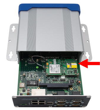
Example of AT&T's IoT Sim card installed in a RediGate (note the three embedded SIM sizes: Mini, Micro, and Nano):
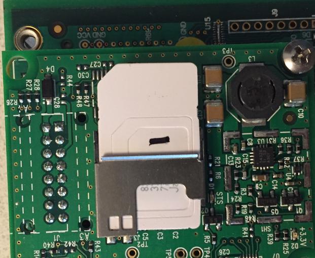
Step 4:
Gently slide the RediGate back into its enclosure and carefully replace the five mounting screws to avoid over-tightening.
Replace the rubber end cap and all front panel connectors.
MULTI-I/O Board
Certain models of RediGate provide an analog/digital module, allowing the RediGate to be used for data acquisition from up to 16 analog inputs, 8 digital inputs, and 2 analog outputs. The Multi-I/O module (Eurotech model AIM104-MULTI I/O) is factory installed inside the RediGate. A 50-way 'D' type connector allows connection to the field signals using an external screw termination block.
Multi-I/O Specifications
Power Consumption | 2.4 Watts, excluding loop power |
| Link setting | |
|---|---|
Analog Mode | 16 channel AI single-ended (LK3 fitted, LK4-A) |
Board #1 address | LK1 jumpers: A2, A3, A4, A6 [0x3A0] |
| Board #2 address | LK1 jumpers: A3, A4, A6 [0x3A4] |
Digital Inputs | |
|---|---|
Number of inputs | 8 opto-isolated digital inputs |
Switching Voltage Range | 10 V to 30 V |
Maximum Input Frequency | 50 Hz |
Isolation | 1000 V to field |
Protection | Reverse protection diodes |
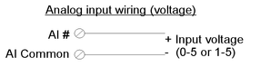
Analog Inputs | |
|---|---|
Number of inputs | 16 single-ended (non-isolated) |
Voltage/current range | 0 to 5 Vdc (0 to 20 mA with external 250) |
Resolution | 12 bits |
Opto-isolation | 1000 V to field |
Input Impedance | 10 M, 10 pF typical |
Relative Accuracy | ±2 LSB (max) @ 25ºC |
Analog Outputs | |
|---|---|
Number of outputs | 2 |
Voltage/Current Range Options | 0 to 20 mA |
Resolution | 12 bits |
Isolation | 1000 V to field |
Output Impedance | Vout =< 10 |
Accuracy | ±2 LSB (max) @ 25ºC |
Multi-I/O Wiring
![]() WARNING: DO NOT CONNECT OR DISCONNECT CABLES WHEN ENERGIZED, UNLESS POWER HAS BEEN REMOVED FROM THE EQUIPMENT OR THE AREA IS KNOWN TO BE FREE OF IGNITABLE CONCENTRATIONS OF FLAMMABLE SUBSTANCES.
WARNING: DO NOT CONNECT OR DISCONNECT CABLES WHEN ENERGIZED, UNLESS POWER HAS BEEN REMOVED FROM THE EQUIPMENT OR THE AREA IS KNOWN TO BE FREE OF IGNITABLE CONCENTRATIONS OF FLAMMABLE SUBSTANCES.
When an optional Multi-I/O board is included with the RediGate 400, it is typically made available on the rear of the enclosure using a 50-way 'D' type connector. An interconnecting 'D' male-male cable and 50-way DIN rail mountable screw termination block are supplied for easy access to field wiring. These accessories are identified with the following part numbers:
Termination block – Elecsys stock code #15-2315-50 (such as Phoenix Contact p/n 2315201)
50-way cable – Elecsys stock code #47-0060-50 (such as L-COM p/n CSMN50MM-2.5)
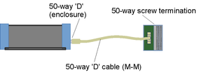
NOTE: When making connection to field I/O, note that the 50-way 'D' type connector on the rear of the RediGate 400 has a different pin numbering from the interconnecting cable and screw termination block. See the following table.
The following table lists the I/O function, pin designations, and screw terminal numbers on the external termination block.
Function (MULTI-I/O) | 50-way 'D' pin (enclosure) | 50-way screw termination |
Digital Inputs | ||
|---|---|---|
DI Common | 1 | 1 |
DI 1 | 2 | 34 |
DI 2 | 3 | 18 |
DI 3 | 4 | 2 |
DI 4 | 5 | 35 |
DI 5 | 6 | 19 |
DI 6 | 7 | 3 |
DI 7 | 8 | 36 |
DI 8 | 9 | 20 |
DI Common | 10 | 4 |
Analog Inputs | ||
AI Common | 20 | 40 |
AI 1 | 12 | 21 |
AI 2 | 13 | 5 |
AI 3 | 14 | 38 |
AI 4 | 15 | 22 |
AI 5 | 16 | 6 |
AI 6 | 17 | 39 |
AI 7 | 18 | 23 |
AI 8 | 19 | 7 |
AI 9 | 22 | 8 |
AI 10 | 23 | 41 |
AI 11 | 24 | 25 |
AI 12 | 25 | 9 |
AI 13 | 26 | 42 |
AI 14 | 27 | 26 |
AI 15 | 28 | 10 |
AI 16 | 29 | 43 |
AI Common | 30 | 27 |
Analog Outputs | ||
Current output: | ||
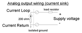
AO 1 Current Loop | 34 | 12 |
AO 1 Current Return | 36 | 29 |
AO 2 Current Loop | 38 | 46 |
AO 2 Current Return | 40 | 14 |
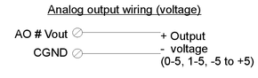
Voltage output: | ||
AO 1 Vout | 43 | 15 |
CGND | 35 | 45 |
AO 2 Vout | 44 | 48 |
CGND | 39 | 30 |
(unused CGND pins) | 11, 21, 31 | 37, 24, 11 |
(not connected) | 32, 33, 37, 41, 42, 45, 46, 47, 48, 49, 50 | 44, 28, 13, 47, 31, 32, 16, 49, 33, 17, 50 |
Some typical wiring diagrams are shown below. Ensure that connections are made to the appropriate termination number for each input or output type, and that the configuration is set correctly for the board number and analog input type (see RediGate 400 Hardware Manual#Multi-I/OSoftwareAccess). 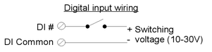

Multi-I/O Software Access
To read the analog or digital inputs and write to the analog outputs, use either ACE-defined POD logic ("PC-104 MULTI-IO-se" function) or an ISaGRAF program (include the "AIMMLTIO" board). In either case, the board parameters should include the Board Address (see RediGate 400 Hardware Manual#MULTI-I/OBoard), and the data should be made available in appropriate RTDB addresses.
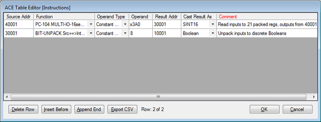
The following screen capture is an example of POD logic using the Multi-I/O board. The Operand for the PC-104 MULTI-IO-16se function is "x3A0" to represent the Board #1 address as hexadecimal. Analog input data is stored starting from the 2nd register (e.g. 30002-30017), and analog outputs are written from the Source Addr (e.g. 40001-40002). The BIT-UNPACK function is optional and may be used to move the bits (e.g. addresses 10001-10008) out of the packed analog RTDB registers (e.g., 30001). The last four registers (e.g. 30018-30022) store low-speed counters for the first four digital inputs, up to about 10 Hertz. See the POD Programming Manual for more information on using POD logic.
When writing to analog outputs using the PC-104 MULTI-IO-16se POD function, values 0 to 4095 represent voltages of -5 to +5 volts. Analog input values using the POD function represent voltages 0 to +5V as integer values 0 to 4095.
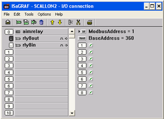
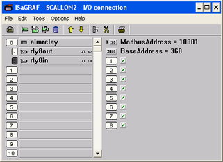
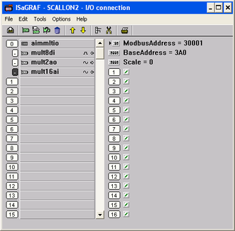
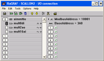
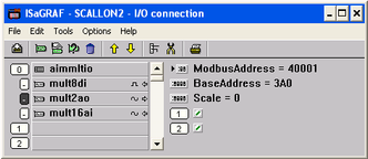
The following screen captures are an example of the I/O connection in ISaGRAF when using the Multi-I/O board. Analog and digital input values are stored in the ISaGRAF RTU and must be polled into an RTDB using the Internal Channel configuration, so that data can be made available to other systems. Analog outputs must be written to the ISaGRAF RTU.
The "Scale" parameter for the analog inputs (mult16ai) determines the scale for the registers values read in the range of 0-4095. The Scale should be set as follows:
00-5 volts = 0-20 mA through 250 ohm resistor
11-5 volts = 4-20 mA through 250 ohm resistor
20-4 volts = 0-20 mA through 200 ohm resistor
30.8-4 volts = 4-20 mA through 200 ohm resistor
The "Scale" parameter for the analog outputs (mult2ao) determines the scale for register values written in the range of 0-4095 to control outputs. The Scale should be set as follows:
00-5 volts = 0-20 mA through 250 ohm load
11-5 volts = 4-20 mA through 250 ohm load
Relay8/IN8 Board
Certain models of RediGate provide a digital I/O module, allowing the RediGate to be used for data acquisition from up to 8 digital inputs and 8 Form C relay outputs. The Relay8/IN8 module (Eurotech model AIM104-RLY8/IN8) is factory installed inside the RediGate. A 50-way 'D' type connector allows connection to the field signals using an external screw termination block.
Relay8/IN8 Specifications
Power Consumption | 1.25 Watts, excluding loop power |
| Link Settings | |
|---|---|
Board #1 address | LK1 jumpers: A2, A3, A4, A7 [0x360] |
Board #2 address | LK1 jumpers: A3, A4, A7 [0x364] |
| Input filter (de-bounce) | LK2A-H fitted |
Digital Inputs | |
|---|---|
Number of inputs | 8 opto-isolated digital inputs |
Switching Voltage Range | 10 V to 30 V |
Maximum Input Frequency | 50 Hz with de-bounce filter enabled |
Isolation | 1500 V to field |
Protection | Reverse protection diodes |
Digital Outputs | |
|---|---|
Number of outputs | 8 Form C relay outputs |
Switching Range | Voltages up to 48 V and currents up to 1.0 A |
Isolation | 1500 V to field |
Relay8/IN8 Wiring
![]() WARNING: DO NOT CONNECT OR DISCONNECT CABLES WHEN ENERGIZED, UNLESS POWER HAS BEEN REMOVED FROM THE EQUIPMENT OR THE AREA IS KNOWN TO BE FREE OF IGNITABLE CONCENTRATIONS OF FLAMMABLE SUBSTANCES.
WARNING: DO NOT CONNECT OR DISCONNECT CABLES WHEN ENERGIZED, UNLESS POWER HAS BEEN REMOVED FROM THE EQUIPMENT OR THE AREA IS KNOWN TO BE FREE OF IGNITABLE CONCENTRATIONS OF FLAMMABLE SUBSTANCES.
When an optional Relay8/IN8 board is included with the RediGate 400, it is typically made available on the rear of the enclosure using a 50-way 'D' type connector. An interconnecting 'D' male-male cable and 50-way DIN rail mountable screw termination block are supplied for easy access to field wiring. These accessories are identified with the following part numbers:
Termination block – Elecsys stock code #15-2315-50 (such as Phoenix Contact p/n 2315201)
50-way cable – Elecsys stock code #47-0060-50 (such as L-COM p/n CSMN50MM-2.5)
NOTE: When making connection to field I/O, note that the 50-way 'D' type connector on the rear of the RediGate 400 has a different pin numbering from the interconnecting cable and screw termination block. See the following table.
The following table lists the I/O function, pin designations, and screw terminal numbers on the external termination block.
Function (RELAY8/IN8) | 50-way 'D' (enclosure) | 50-way screw termination |
Digital Inputs | ||
|---|---|---|
DI Common | 1 | 1 |
DI 1 | 2 | 34 |
DI 2 | 3 | 18 |
DI 3 | 4 | 2 |
DI 4 | 5 | 35 |
DI 5 | 6 | 19 |
DI 6 | 7 | 3 |
DI 7 | 8 | 36 |
DI 8 | 9 | 20 |
DI Common | 10 | 4 |
Digital Outputs | ||
Relay 1 Common | 12 | 21 |
Relay 1 Normally Open | 13 | 5 |
Relay 1 Normally Closed | 14 | 38 |
Relay 2 Common | 17 | 39 |
Relay 2 Normally Open | 18 | 23 |
Relay 2 Normally Closed | 19 | 7 |
Relay 3 Common | 22 | 8 |
Relay 3 Normally Open | 23 | 41 |
Relay 3 Normally Closed | 24 | 25 |
Relay 4 Common | 27 | 26 |
Relay 4 Normally Open | 28 | 10 |
Relay 4 Normally Closed | 29 | 43 |
Relay 5 Common | 32 | 44 |
Relay 5 Normally Open | 33 | 28 |
Relay 5 Normally Closed | 34 | 12 |
Relay 6 Common | 37 | 13 |
Relay 6 Normally Open | 38 | 46 |
Relay 6 Normally Closed | 39 | 30 |
Relay 7 Common | 42 | 31 |
Relay 7 Normally Open | 43 | 15 |
Relay 7 Normally Closed | 44 | 48 |
Relay 8 Common | 47 | 49 |
Relay 8 Normally Open | 48 | 33 |
Relay 8 Normally Closed | 49 | 17 |
(not connected) | 11, 15, 16, 20, 21, 25, 26, 30, 31, 35, 36, 40, 41, 45, 46, 50 | 37, 22, 6, 40, 24, 9, 42, 27, 11, 45, 29, 14, 47, 32, 16, 50 |
Some typical wiring diagrams are shown below. Ensure that connections are made to the appropriate termination number for each input or output type, and that the configuration is set correctly for the board number and analog input type (see RediGate 400 Hardware Manual#Relay8/IN8SoftwareAccess). 
Relay8/IN8 Software Access
To read the digital inputs and write to the digital outputs, use either ACE-defined POD logic ("PC-104 IN-8" and "PC-104 OUT-8" functions) or an ISaGRAF program (include the "AIMRELAY" board). In either case, the board parameters should include the Board Address (see Relay8/IN8 Specifications), and the data should be made available in appropriate RTDB addresses.
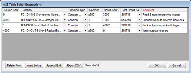
The following screen capture is an example of POD logic using the Relay8/IN8 board. The Operand for the PC-104 IN8 and PC-104 OUT8 functions is "x360" to represent the Board #1 address as hexadecimal. The BIT-PACK and BIT-UNPACK functions are optional and may be used to move the bits (e.g. addresses 1-8 and 10001-10008) into and out of packed analog RTDB registers (e.g., 30001, 40001). See the POD Programming Manual for more information on using POD logic.
The following screen captures are an example of the I/O connection in ISaGRAF when using the Relay8/IN8 board. Digital input and output values are stored in the ISaGRAF RTU and must be polled into an RTDB using the Internal Channel configuration, so that data can be made available to other systems.