...
| Table of Contents | ||
|---|---|---|
|
...
Introduction
The RediGate Configuration Manual describes the configuration of many of the RediGate's standard features using the ACE program. This document gives additional instructions for configuring the RediGate to use the following protocols:
...
| Include Page | ||||
|---|---|---|---|---|
|
Allen Bradley DF1 & CSP Protocol Description
...
The RediGate's DF1 and CSP protocols over an Ethernet connection is also referred to as PCCC. This document does not describe configuration of Allen Bradley EtherNet/IP CIP protocol. The RediGate does not currently support Data Highway Plus (DH+), which requires a special hardware interface.
The following sections describe the ACE objects used for DF1 and CSP Master, object properties (including constraints on the Instance number), and object fields and their possible values required to configure for the given protocol(s). The object structure in ACE is hierarchical, with each object existing under a certain parent object. For instance, the FieldUnit is the child of one of several types of Circuit objects, either serial or network type (" System>Clients>Master Channels>Master Channel>Circuit").
...
- For the DF1 protocol, do not use the actual TCP port in this for the Master Network Port. The RediGate will automatically default to using port number 44818.
Instead, set the Master Network Port property to the slot number in the PLC containing the PLC CPU. Often, this will be 0, but check with the PLC setup. - For the CSP protocol, use Master Network Port = 2222.
- Set the Circuit Type to be "Network DF1 Circuit" (not the default "Network Circuit" option).
- Set the Connect Table to the IP address of the PLC.
See the RediGate Configuration Manual for information on configuring the NetCircuit object.
...
If using a Df1Rs232circuit for serial DF1 devices, make sure to include a COM port (System>Networks>AsyncPort) object in the configuration with the instance number matching the physical COM port, and the baud rate corresponding to the field device’s setting.
See the RediGate Configuration Manual for information on configuring the AsyncPort.
...
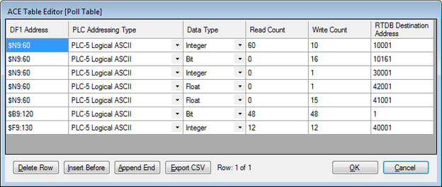
As an example of a continuation poll, assume that the DF1 PLC has statuses, accumulators, controls, and setpoints all packed into different boards located at $N9:60 through $N9:119 registers (using PLC-5 Logical ASCII format). Below is an example poll table with this information.
| Warning | ||
|---|---|---|
| ||
You must have data in the registers that you are polling, otherwise you receive errors on that poll record during that poll attempt. For example, there are only 2 $F8 registers declared in this PLC program:
Attempting to poll register $F8:2 will result in an error. |

...
Rows 6 and 7 may be included as entries in the Master Channel's Scan Table, but only if the RediGate needs to read the binary control bits and analog setpoint values from the PLC continuously. If it is only necessary for a host system to write to these control registers (not read the feedback)—for instance, if the control feedback is obtained from reading other DF1 registers—the Poll Table definitions are still required in order to map Modbus RTDB registers to DF1 device point numbers, but there is no need to include Scan Table entries for these polls (see Master Channel on page ).
Modbus RTDB
See the RediGate Configuration Manual for information on configuring the RTDB.