RediGate Configuration Manual
- Jon Tandy
- Former user (Deleted)
- Jon Tandy (Deactivated)
- Former user (Deleted)

Product Information
Full information about other Elecsys products is available on our website at www.elecsyscorp.com and the RediGate Product Support page.
Product Support
Tel: +1-913-890-8905
Fax: +1-913-982-5766
Email: idc-support@elecsyscorp.com
Headquarters, Sales, Support & Manufacturing
Elecsys Corporation
846 N Mart-Way Court
Olathe, KS 66061
Tel: +1-913-647-0158
Fax: +1-913-982-5766
Email: info@elecsyscorp.com
While Elecsys may assist customers with their choice of products, the final choice of product for a specific application is entirely the responsibility of the buyer. Elecsys' entire liability with respect to its products or systems is defined in the Elecsys standard terms and conditions of sale.
Any example code is provided only to illustrate the use of Elecsys products. No warranty, either expressed or implied, is made regarding any example code provided by Elecsys and Elecsys shall incur no liability whatsoever arising from any use made of this code.
Disclaimers
The information in this manual is believed to be accurate at the time of publication. Elecsys Corporation assumes no responsibility for inaccuracies that may be contained in this document and makes no commitment to update or keep current the information contained in this manual. Elecsys Corporation assumes no responsibility for any infringements of patents or other rights of third parties that may result from its use. Elecsys Corporation reserves the right to make changes or improvements to this document and/or product at any time and without notice. While Elecsys may assist customers with their choice of products, the final choice of product for a specific application is entirely the responsibility of the buyer. Elecsys' entire liability with respect to its products or systems is defined in the Elecsys standard terms and conditions of sale.
Any example code is provided only to illustrate the use of Elecsys products. No warranty, either expressed or implied, is made regarding any example code provided by Elecsys and Elecsys shall incur no liability whatsoever arising from any use made of this code.
Electrostatic Discharge (ESD) Protection
These units contain devices that could be damaged by the discharge of static electricity. At all times, please observe industry standard ESD precautions when handling the unit.
![]() WARNING: DO NOT CONNECT OR DISCONNECT CABLES WHEN ENERGIZED, UNLESS POWER HAS BEEN REMOVED FROM THE EQUIPMENT OR THE AREA IS KNOWN TO BE FREE OF IGNITABLE CONCENTRATIONS OF FLAMMABLE SUBSTANCES.
WARNING: DO NOT CONNECT OR DISCONNECT CABLES WHEN ENERGIZED, UNLESS POWER HAS BEEN REMOVED FROM THE EQUIPMENT OR THE AREA IS KNOWN TO BE FREE OF IGNITABLE CONCENTRATIONS OF FLAMMABLE SUBSTANCES.
© 2024 Elecsys Corporation
Table of Contents
Introduction
The RediGate is a multi-application remote data communications computer/data integration device. It provides a wide array of SCADA and other communication and logic processing functionality. In order to configure the operational characteristics of the RediGate, Elecsys provides the Advanced Configuration Environment (ACE) program. This manual describes the configuration objects of the RediGate, including the standard features and some of the optional properties that may be specific to some customer installations.
Note: Due to project-specific requirements or on-going product development, some configuration templates may contain more or fewer objects than are described in this manual. This manual should be treated as a guide to understanding the basic RediGate configuration, but project documentation may contain additional details.
It is assumed that the user has already installed the ACE Editor and is familiar with the ACE configuration tools. Please refer to the ACE Operation Manual for more details on installation and use of ACE.
This manual includes some detail on configuring the RediGate ACE objects for communication to an HCP. However, see HCP documentation for additional information on setting up HCP and RediGate configurations, in order to fine-tune the SCADA system operation for optimal performance.
This manual omits many of the protocol-specific details for configuring master or slave communication to various proprietary protocol-based devices. Elecsys provides a number of supplementary protocol-specific manuals documenting the ACE objects for individual protocols.
This manual also does not cover programming the RediGate using the ISaGRAF development environment or POD logic. See the Elecsys ISaGRAF Manual and POD Programming Manual for that information.
ACE Configuration Program
Within the ACE Editor, a configuration is made up of a collection of "objects." Each configuration object is represented by an icon and contains general properties and specific fields that provide operational settings for the RediGate and/or HCP.
This manual provides reference information on the configuration objects within the ACE Editor. Each section gives a description of the object's purpose and functionality, the graphical icon, and also a section describing the object Properties and Fields. Icons shown in this manual include newer style icons, as well as older historic icons for reference.
Each section gives the "Parent" of the object, showing the hierarchical tree of parent objects in the configuration. For instance, the AsyncPort is the child of the System and Networks objects ("System>Networks").
Each sub-section describes the ACE object and its properties (including constraints on the Instance number), and object fields and their possible values. The Instance Number is a required element of many ACE objects, and allows multiple instances of the same object type under the same parent to be identified uniquely.
Each object includes a Description property, which allows the system designer to include some descriptive text about the purpose or use of the object. Each object includes an Enabled property. If an object is disabled, then the object and all of its child object hierarchy are effectively disabled and will not be used in the device operational settings.
The "UFF External" property is only mentioned for certain objects where it is typically used, but it should normally be left unchecked. This property allows the configured values for certain ACE objects to be loaded and used in the RediGate separately from the main configuration file.
System and Networking Objects
This section describes the ACE objects for the top-level system objects, the configuration of serial and network interfaces, and other networking protocols.
System Configuration
![]()
The RediGate System object is the parent object for all the other objects in the configuration. It contains some base properties for the RediGate operation.
| Attributes | Function |
|---|---|
| Object Type | System |
| Parent(s) | N/A |
| Properties | Values |
|---|---|
| Unit Address | Enter a valid and unique unit address between 1 and 255. The Unit Address is used in some host systems: - Identifies this unit in an Elecsys HCP (must be unique) - Identifies this unit in an Elecsys OPC Server (must be unique) - May be part of topic string to MQTT broker/OPC Server, if configured in the MQ RBE object (must be unique if using Topic option with "UnitAddress") Note that the "Unit Address" property is different from any individual Field Unit being polled and reported to the host. The Unit Address refers to the RediGate itself, and must be explicitly configured to be unique across all devices reporting to the HCP or MQTT/OPC Server. |
| Unit Name | Depending on the configuration, the User Name may be up to a length of either 13 or 128 characters. The Unit Name is used to identify this unit in diagnostics menus and is also used with some host systems: - Identifies this unit in an Elecsys HCP (must be unique) - Identifies this unit in an Elecsys OPC Server (must be unique) - May be part of topic string to MQTT broker/OPC Server, if configured in the MQ RBE object (must be unique if using Topic option with UnitName) Note that this "Unit Name" property is different from any individual Field Unit name configured in other ACE objects and reported to the host. The Unit Name refers to the RediGate itself, and must be explicitly configured to be unique across all devices reporting to the HCP or MQTT/OPC Server. |
| User Name | Enter a valid password between 1 and 13 characters. User name is a NULL terminated character string, used for setting up a user account for MMI and file system access. |
| Password | Enter a valid password between 1 and 8 characters. Password is a NULL terminated character string, used for setting up a user account for MMI and file system access. A NULL string value will disable password protection for the MMI over a network connection, but a 'root' user will still be able to access the MMI. |
| Date Format | Select the date format to specify which time zone to use for the internal system clock. The values in parentheses are the Linux localtime filenames used for adjusting the clock. Options are: Universal Coordinated Time=GMT (UTC) U.S. Eastern Time (EST5EDT) U.S. Eastern, no daylight savings (EST) U.S. Central Time (CST6CDT) U.S. Mountain Time (MST7MDT) U.S. Mountain, no daylight savings (MST) U.S. Pacific Time (PST8PDT) Great Britain Time (GB) Western Europe Time (WET) Central Europe Time (CET) Eastern Europe Time (EET) |
Linux System Object
![]()
![]()
The RediGate system consists of RediGate application software that runs within a Linux operating system. The "RediGate" functionality is generally concerned with protocol gateway, SCADA operations and data communication (Master/Slave channels, Terminal Server/Client, etc.). Other functions (primarily networking) are handled directly in the Linux operating system.
The System Configuration object (described in the section 2-System and Networking Objects#System Configuration) and many of its child objects are used to configure software components specifically related to the core application software. Other ACE objects (such as network settings, NTP, etc.) are used to configure components which are part of the Linux operating system, but which operate independently of the gateway application.
In many cases, a customer may wish to use ACE to fully manage all of these Linux services, including the disabling of non-configured items. For instance, a customer may wish to explicitly disable the DHCP Server, which can be done by disabling or removing the DHCP Server ACE object from the configuration. Other customers may desire certain network or Linux system components to be managed by their IT department, separate from the RediGate application and ACE configuration environment (in keeping with security or other corporate network administration policies).
The Linux System icon is included in the configuration to allow the flexibility of independent management of certain Linux-level OS features. The "Linux System" ACE object tells the RediGate how to handle these services when processing a new ACE configuration file. It includes a list of Linux system components which are outside the specific RediGate application capabilities, and allows a customer to determine whether the service will be managed by the ACE configuration or separately.
| Attributes | Function |
|---|---|
| Object Type | LinuxSystem |
| Parent(s) | System |
| Instance | Must be 0 |
| Properties | Values |
|---|---|
| Linux Services | Click the Edit Table button to edit the list of system-managed services, defining how the RediGate should handle these services. By default, the RediGate will actively manage Linux services — this means if the configuration object is missing or disabled, the RediGate will remove those services. If the object is present (and enabled) in the configuration, the RediGate will configure those services. However, in some cases, the customer may wish to independently manage these Linux services, such as the IT department taking care of periodic password updates independent of the ACE configurations, or managing other Linux services (Firewall, etc.) from the command line. In these cases, you must add an entry to the Linux Services table and set the option to "Customer-managed service" to prevent ACE from enabling, disabling, or configuring the service. Service Name – Select the Linux service from the list of available services. Services in the Linux System object include: Hostname – Configured in the System configuration object. By default, this sets the Linux system name when logging into the command prompt. ManagedBy – Select how the service should be managed whenever a new ACE configuration is downloaded to the unit. Options include: ACE should manage service – Uploading an ACE configuration will configure the service (if configured), or delete the service (if not present or object is disabled in ACE). Hostname, User Password and Timezone will be set in Linux according to the properties which appear in the System configuration object. If the Linux System object is not included in the configuration, or if the Service Name option is not present in the table, this is the default option. |
Networks
![]()
![]()
The Networks placeholder is the parent for objects that define the physical communications connections for the system. The RediGate is capable of supporting up to a certain number of serial and network communication ports with a wide array of operational parameters. The maximum number of ports available depends on the limitations of the individual hardware platform (see the appropriate Hardware Manual for details).
| Attributes | Function |
|---|---|
| Object Type | Networks |
| Parent(s) | System |
| Instance | Must be 0 |
Ethernet Port
![]()
![]()
The Ethernet Port configuration defines the operational properties of a physical Ethernet port on the device.
| Attributes | Function |
|---|---|
| Object Type | EtherPort |
| Parents | System → Networks |
| Instance | Enter a unique instance number between 0 and 16. The instance number is required to correspondwith the Linux interface name for the Ethernet. Instance #0 and 1 configure the built-in 'eth0' and 'eth1' ports, and Instance #2 configures the 'eth2' port of the optional AIM104-ETHER. |
| Properties | Values |
|---|---|
| Network Card Type |
|
| MTU (Network Card Address) | (Network Card Address included only for compatibility with older ACE objects) When "Ethernet" option is selected for Network Card Type, set the Maximum Transmission Unit (MTU). Default is 1500 (ignored if less than 256). |
| MRU (Network Card IRQ) | (Network Card IRQ included only for compatibility with older ACE objects) When "Ethernet" option is selected for Network Card Type, set the Maximum Receive Unit (MRU). Default is 1500 (ignored if less than 256). |
| Network Card DMA | (Included only for compatibility with older ACE objects) |
| Domain Name | Enter a unique name for this interface, used in certain ACE objects to identify this network adapter. This is case-sensitive. |
| Network Card IP | Enter the IP address for the Ethernet adapter, in dotted notation. To set the Ethernet to use DHCP client(to obtain an IP address, subnet, and default gateway from a DHCP server), set the Network Card IP to 0.0.0.0. |
| Subnet Mask | Enter the subnet mask, in dotted notation. Make sure that all IP interfaces are configured for non-overlapping subnets. If using DHCP client, this field is ignored and may be set to 0.0.0.0. |
| Default Gateway | Enter the default gateway, which is the IP address of a router for the RediGate to connect to addresses beyond its local subnet. If a default gateway is configured in a Routes object in the configuration, or if there is no default gateway to be configured, set this property to 0.0.0.0. If using DHCP client, this field is ignored and may be set to 0.0.0.0. |
Multi-Home
![]()
![]()
The Multi-Home configuration allows additional IP addresses to be defined on the same Ethernet interface. This object should be omitted unless more than one IP address must be defined.
| Attributes | Function |
|---|---|
| Object Type | Multi-Home |
| Parent(s) | System → Networks → EtherPort |
| Instance | Must be 0 |
| Properties | Values |
|---|---|
| IP Homes | Click the Edit Table button to edit the list of Multi-Home addresses. Network Card IP – Enter the additional IP address to be used, in dotted notation (do not include the primary IP address defined in the Ethernet object). |
DHCP Server
![]()
![]()
The DHCP Server is a child object to an Ethernet interface, and defines the ability to act as a DHCP server to other devices on that network, responding to DHCP requests, assigning address, subnet, default gateway, and DNS
| Attributes | Function |
|---|---|
| Object Type | DHCP Server |
| Parent(s) | System → Networks → EtherPort |
| Instance | Must be 0 |
| Properties | Values |
|---|---|
| LAN Interface Name | Enter the Linux interface name of the Ethernet port on which to run the DHCP server. |
| LAN Subnet Address | Enter the subnet address of the subnet that should be served to clients as part of the DHCP information, in dotted notation. Subnet address should follow normal IP rules (for instance, on a 192.3.1.x network with 255.255.255.0 subnet mask, the subnet address would be 192.3.1.0). |
| LAN Subnet Mask | Enter the subnet mask of the subnet that should be served to clients, in dotted notation. |
| Served Address Range Start IP | Enter the starting IP address that should be served to clients, in dotted notation. |
| Served Address Range End IP | Enter the ending IP address that should be served to clients, in dotted notation. The range of addresses between the Start IP and End IP determines how many DHCP clients be supported simultaneously on the interface. |
| Served Default Gateway | Enter the address of the Default Gateway to be served to DHCP clients, in dotted notation. |
| Served Domain Name | Enter the domain name to be served to DHCP clients (must be from 1 to 64 characters). |
| Served DNS Server Primary | Enter the address that will be served to DHCP clients as their primary DNS server, in dotted notation. |
| Served DNS Server Secondary | Enter the address that will be served to DHCP clients as their secondary DNS server, in dotted notation. |
| Served Broadcast Address | Enter the address that will be served to DHCP clients as the broadcast IP. The broadcast IP should follow normal IP rules (for instance, on a 192.3.1.x network with 255.255.255.0 subnet mask, the broadcast IP address would be 192.3.1.255). |
| Lease Time-Default | Enter default lease time, in seconds |
| Lease Time-Max | Enter the maximum lease time, in seconds. |
| Authoritative | Select whether or not to make this DHCP Server "authoritative." Setting this to "No" means that if a client requests an address that the server knows nothing about and the address is incorrect for that network segment, the server will not send a DHCPNAK (which tells the client it should stop using the address.) Setting this to "Yes" will send a DHCPNAK in this case, to force the client to stop using the incorrect address on the network and immediately request a new address. |
Async Port
![]()
![]()
The Async Port configuration defines the asynchronous serial communication properties of a physical serial port. Do not configure an Async Port object for any serial port used as an IP network, such as PPP or SLIP.
Note:
Async ports can be defined as "Virtual Ports," that represent internal software links between tasks rather than actual, physical communication ports. For additional information, see the section Virtual Ports.
| Attributes | Function |
|---|---|
| Object Type | AsyncPort |
| Parent(s) | System → Networks |
| Instance | Enter a unique instance number between 0 and 127. When configuring physical serial ports, the instance number must match the COM port number in the Linux system. For RediGate 1xx series, you must use instance 2 for COM2. For built-in Zeus processor ports, use instance numbers 0 through 3 for COM0-COM3 (Linux /dev/ttyS0 through /dev/ttyS3). For the AIM104-COM8 expansion card, use instance numbers 4 through 11 for COM4-COM11 (Linux /dev/ttyS4 through /dev/ttyS11). To configure virtual serial ports, see the section 2-System and Networking Objects#Virtual Ports. |
| Properties | Values |
|---|---|
| Baud Rate | Select baud rate for the Async Port speed. For the Serial MMI port, typically use 115,200. Otherwise, set the serial properties according to the communication requirements of the external devices. |
| Parity | Select the parity for the serial port (None, Odd, or Even). |
| Word Length | Select the data bits for the serial port (7 or 8 bits). |
| Stop Bits | Select the stop bits for the serial port (1 or 2 bits). |
| Rx Buffer Size | Enter the receive buffer size in bytes. The receive buffer holds incoming data while waiting for processing by the application. |
| Tx Buffer Size | Enter the transmit buffer size in bytes. The transmit buffer holds outgoing data while waiting for the serial port hardware to deliver the data. For the Serial MMI port, use at least 2048, to allow the MMI to transmit large blocks of diagnostic data. |
| Warm Up Time | Enter value for warm up time. This is the amount of time to wait before sending data after the RTS handshaking lead has been asserted. |
| Warm Down Time | Enter value for warm down time. This is the amount of time to wait after the entire message packet has been shifted out to keep the RTS handshaking lead asserted. There are three modes of operation based on the Warm-up and Warm-down settings: No Handshaking – Set both the Warm-up and Warm-down to a value of -1. RTS will not be activated, CD is not required. Hardware Handshaking – Set both the Warm-up and Warm-down to a value of -1. RTS will not be activated, CD is not required. Timed Handshaking – Set either the Warm-up or Warm-down or both to positive numbers. RTS will be asserted for the configured Warm-up time, then data will be sent regardless of the condition of CTS. After data has been sent, RTS will be asserted for the configured Warm-down time, and then lowered. When using the Async Port with an RS-485 device, modem, or external HART device, typically requires the Warm-up and Warm-down to be set to 0 or a fixed positive integer for hardware flow control. |
Virtual Ports
![]()
![]()
This section describes the "Virtual Port" feature of the RediGate. Virtual Ports are configured as Async Ports which do not define physical communication hardware, but rather internal communication links.
The purpose of Virtual Ports is to connect two different internal processes that ordinarily communicate over a physical serial port. Rather than using two actual serial ports and connecting them together using a null modem cable, the Virtual Ports connect the processes internally via a software link. Data from one process is immediately transferred to the other and vice-versa.
Several rules must be understood to use Virtual Ports:
- Virtual Ports use the same object definition as Async Ports (see the section 2-System and Networking Objects#Async Port).
- Virtual Ports may be selected in objects (such as Circuits) in the same way that Async Ports are selected, and use Instance numbers 52 through 67.
- Virtual Ports must always be created and used in pairs, and pass data from one to the other in the same way as an external null modem cable between physical comm ports. COM52 is connected to COM53, COM54 to COM 55, etc.
- If you are using the Elecsys cellular modem and have "Enable Serial MUX" set to Yes, the Mux automatically opens virtual ports 72, 74, and 76 for AT command and GPS access to the modem. In this case, these sets of virtual ports may only be used with the child ports under the CellModem object. ACE objects for ports 73, 75, or 77 (the corresponding virtual pairs of ports associated with 72, 74, and 76, respectively) should be defined as child objects under the CellModem, not under Networks.
| Attributes | Function |
|---|---|
| Object Type | AsyncPort |
| Parent(s) | System → Networks |
| Instance | Enter a unique instance number between 0 and 127 Virtual Ports must be added in pairs, using instance numbers: 52 & 53, 54 & 55, up to 66 & 67 |
| Properties | Values |
|---|---|
| Baud Rate, etc | When configuring Virtual Port definitions, all fields in the Async Port object are unused, and are simply included for compatibility with other physical Async Port objects. |
Cell Modem
![]()
![]()
The CellModem configuration defines the configuration for a PPP (Point-to-Point Protocol) connection to an Elecsys EModem.
| Attributes | Function |
|---|---|
| Object Type | CellModem |
| Parent(s) | System → Networks |
| Instance | Enter a unique instance number between 0 and 18. Instance #0 is the configuration for the numbered interface, such as 'ppp0. |
| Properties | Values |
|---|---|
| PPP Port | Select the physical communication port to be used for PPP. This should be an internal port to which the cell modem is physical connected. This should typically be COM8 for RG-100 and RG-400. Do not configure the same COM port as an AsyncPort or other type of port in addition to the CellModem configuration. If there are AsyncPort or PPP objects defined for the same physical COM port, neither will work properly. |
| Baud Rate | Select baud rate for the cell modem port. Note: Maximum baud rate for RediGate 100 series is 230.4K. The RediGate 400 series can use 460.8K. |
| Parity | Select the parity for the cell modem port (None, Odd, Even). Parity options supported are None, Odd and Even. Typically, this should be None. |
| Word Length | Select the data bits for the cell modem port (7 or 8 bits). Typically, this should be 8. |
| Stop Bits | Select the stop bits for the cell modem port (1 or 2 bits). Typically, this should be 1. |
| Warm Up Time | Enter value for warm up time. This is the amount of time to wait before sending data after the RTS handshaking lead has been asserted. The default entry of 0 should be used, denoting that RTS/CTS hardware handshaking will be used. |
| Warm Down Time | Enter value for warm down time. This is the amount of time to wait after the entire message packet has been shifted out to keep the RTS handshaking lead asserted. The default entry of 0 should be used, denoting that RTS/CTS hardware handshaking will be used. |
| Domain Name | Enter the domain name. Name used by certain tasks internally to identify different IP adapters. This is case-sensitive. However, in most cases, this is a legacy option that isn't actually used. |
| PPP IP | Enter the PPP IP address. This is the address at which other network devices will see this device when trying to make a connection via PPP. |
| Subnet Mask | Enter the subnet mask. Should always be 255.255.255.255 for PPP. If a static IP is used and a Default Gateway is required to make outbound connections beyond the local subnet, the Routes object must also be configured (see the section 2-System and Networking Objects#Route). |
| Connection TimeToDie | Number of seconds to operate a PPP session before killing the connection. This time is absolute, based on the time at which the session was initiated. The PPP connection will be closed regardless if data is still being transferred when the TimeToDie timer expires. This may be used to force a dial connection to hang up to limit cell phone connection charges. Disable the TimeToDie by setting it to -1 if the connection should never be closed automatically. |
| Modem Type | Select the type of modem being configured. This will depend on the hardware physically available on this device. The model number of the RediGate denotes the type of modem installed. For instance, typically the RG-100C-40-00 or RG-400C-40-00 indicates the Quectel BG96 modem. Options are:
|
| AT Init Strings | Enter one or more optional text entries for AT commands to be sent to the modem upon initialization. Text strings are limited to 80 characters. The AT Init Strings and all built-in modem initialization commands and responses are logged in a file /tmp/modemlog.txt. Consult modem manual for initialization parameters or other AT commands available. NOTES: |
| Connect String | Enter the modem connect string. This is the AT command telling the modem to enter an IP data session and depends on the modem model. For Quectel BG96 CAT-M1 modem, select: ATD*99# For the SARA-R4 CAT-M1 or GSM/HSPA+ modem (HE910), select: ATD*99***1# For EVDO modem (DE910-DUAL), select: ATDT#777 |
| Enable Serial MUX | Select whether to use a serial multiplexer to the modem. This should typically be set to 'Enabled'. The serial multiplexer allows the data PPP session and other diagnostics to occur simultaneously to the modem. See the sections 2-System and Networking Objects#Modem Ports 73/75/77 and 2-System and Networking Objects#AT Commands for other options that can be used |
| Use as Default Gateway | Select whether to use this cell modem network as the Default Gateway. Typically this should be set to 'Yes'. |
| Network Inactivity Watchdog | Enter the number of minutes of inactivity to be allowed, before the modem and PPP session will be restarted. This option is not currently supported. |
| APN | Enter the APN (Access Point Name), which is the network gateway through which the cell modem will connect. This is typically dependent on the cellular carrier that the modem is activated on, and may be a public or private APN depending on the cellular account settings. Used for CAT-M1 or GSM/HSPA networks only; leave blank for EVDO networks. |
| Use Peer DNS | Select whether to use DNS from the cellular network provider. |
| Authentication Type | Select the type of PPP Authentication required by the cellular network. This setting and the Auth User Name and Password will depend on the cellular account activation. Authentication types are: Disabled |
| Auth User Name | Enter the user name required by the cellular network for PAP or CHAP authentication. User Name is case sensitive and limited to 32 characters. |
| Auth Password | Enter the password required by the cellular network for PAP or CHAP authentication. Password is case sensitive and limited to 32 characters. |
Modem Ports 73/75/77
![]()
![]()
When the Cell Modem configuration is used with Serial MUX 'enabled', the modem can be queried for operational information simultaneously with the PPP/IP data traffic. This feature can be used for AT commands (reading the modem's signal strength, etc.) and obtaining GPS location.
These modem options require one or more child objects to be configured for the Cell Modem, which are Virtual COM Ports dedicated specifically to the modem. It is recommended to enable the Serial MUX and to define at least Port 73 for AT command access, and the other ports if needed. The ports are identified as follows:
| Port | Description |
|---|---|
| 73 | AT commands, used by the RediGate MMI to query the modem |
| 75 | (for DE910 CDMA/EVDO modem) – AT commands only. Port 75 may be selected in another serial configuration, such as Terminal Server (for HE910 GSM/HSPA modem) – AT commands or GPS NMEA data. Port 75 may be selected in the FieldUnitNMEA object or another serial configuration. |
| 77 | (for DE910 CDMA/EVDO modem) – AT commands or GPS NMEA data. Port 77 may be selected in the FieldUnitNMEA object or another serial configuration. (for HE910 GSM/HSPA modem) – unavailable |
For additional information on the FieldUnitNMEA object, see the section 2-System and Networking Objects#NMEA (GPS) Field Unit. The ports 73, 75, and 77 are defined under the Cell Modem object, and their paired virtual serial ports are internally generated. You should not create AsyncPort objects with instance numbers 72 through 77 under the Networks placeholder.
| Attributes | Function |
|---|---|
| Object Type | Port73b_AT-CMDs, Port75b_AT-CMDs_GPS-HE910, Port77b_GPS-DE910 |
| Parent(s) | System → Networks → Cell Modem |
| Instance | Instance number for each port must be 0. The ACE template is built so that each of these objects creates the appropriate AsyncPort filename: port073, port075, port077 |
| Properties | Values (Port 73) |
|---|---|
n/a (only use for AT command access) |
| Properties | Values (Port 75) |
|---|---|
| Port Settings | Select the AT command or GPS option for this port:
The following selections enable the GPS receiver to automatically output location data in NMEA format once/second (Port 75 only supports GPS on the HE910 modem). NOTE: a GPS antenna connection is only available on the RediGate 400, not the RediGate 100 series. For a description of the NMEA data messages, see theTelit MT GNSS Software User Guide.
|
| Properties | Values (Port 77) |
|---|---|
Same as Port Settings for Port 75, except that it is only applicable to the DE910 modem and should not be used with the HE910. |
USAGE NOTE:
There are two ways to get receive GPS data from the modem into RTDB registers and/or use the GPS date/time to synchronize the RediGate system clock:
1) AT commands This method uses a simpler configuration, but data is obtained less frequently (multiple 10's of seconds, depending on the number of AT commands defined).
Select AT Commands (Power GPS) as the setting for Port 75 or 77, and in the AT Commands object define the $GPSACP command (see the section 2-System and Networking Objects#AT Commands).
2) Real-time NMEA data This method requires a more complicated configuration, but GPS data can be obtained frequently (within a few seconds). More frequent data acquisition from the modem will also potentially impact the bandwidth available to PPP network traffic.
Select one of the GPS port settings for Port 75 or 77. In addition, you will need to define the FieldUnitNMEA (with AsyncCircuit pointing to port 75 or 77) including a Poll Table to define which command(s) to parse into RTDB registers, include the registers in an RTDB, add one or more scan entries in the Master Channel to set the frequency of GPS data storage, and additionally configure the NMEA_SPY object to capture the unsolicited NMEA data into internal memory buffers.
AT Commands
![]()
![]()
When the Cell Modem configuration is used with Serial MUX 'enabled', the modem can be queried for operational information simultaneously with the PPP/IP data traffic. The AT Commands object allows one or more AT commands to be defined that will regularly query the cellular modem. This may be used, for instance, to query cellular signal strength, registration status, etc., and store the information into RTDB registers that can be published with MQTT or shared via a SCADA protocol.
The RediGate regularly sends an AT command to read cellular signal strength in order to control the cellular LED. If any user-configured commands are included in the AT Commands object, those commands will be sent alternately with the built-in signal strength query. AT commands are sent at a regular interval of 5 seconds. For instance, if two user commands are defined to read signal strength and registration status into RTDB registers, the AT command sequence will be:
AT+CSQ(built-in)
(5 seconds)
AT+CSQ(user AT command)
(5 seconds)
AT+CSQ(built-in)
(5 seconds)
AT+CREG?(user AT command)
(5 seconds)
When the response to each user-configured command is received, it is parsed according to certain rules, as described below under the 'Conversion' type field. Often, commands will return a comma-separated list of values. The AT Commands object allows these values to be parsed based on comma.
| Attributes | Function |
|---|---|
| Object Type | AT_Commands |
| Parent(s) | System → Networks → Cell Modem |
| Instance | Always 0 |
| Properties | Values (Port 77) |
|---|---|
| PropertiesValues Timeout Msec | Enter the timeout (in milliseconds) to wait for modem response to AT command. |
| AT Cmds | This table defines any user-configured AT commands to be queried regularly |
| RTDB Map | Enter one or more rows in the AT Cmds table to use this feature |
| AT Command | Enter the AT command string to send to the modem, or a single uppercase character 'C'. The AT string must be a command that is recognized by the modem model being used. If the command returns several different values to be parsed, the 'C' indicates a continuation row. This allows the response from a previous command to be skipped or parsed according to different rules, as described in the remaining properties, below. To use GPS data, the AT Command depends on which modem is being used:
To read a list of available cellular carriers, use the AT Command: AT+COPS=?
where 2 indicates the active carrier, followed by short and long text strings, then the MCC/MNC in one string, and the ACT last. |
| Conversion | Select the type of conversion to use when parsing the command response from the modem.
Latitude stored as ±dddd.dddd (positive=north, negative=south)
|
| Channel | Enter the Master Channel number of the destination RTDB. |
| RTU | Enter the Field Unit address of the destination RTDB. |
| RTDB Dest | Enter the starting numeric register address of the destination RTDB into which data from this command will be stored. The RTDB addresses must be defined and must be of the correct data type. |
| Count | Enter the number of data entities of the same 'Conversion' type to parse sequentially. If the response to an AT command includes multiple values of different types, these must be handled on separate rows in the table, with the Count appropriate for each row. |
| Comment | Optional column, allowing a descriptive comment to be entered for each row in the table. The Comment field is unused in the configuration. |
Registers used for GPS Data (AT Commands)
If using one of the GPS "Conversion" options above, the GPS string obtained from the modem will be parsed according to comma-separated fields and stored sequentially into RTDB registers. The registers should be REAL32 or REAL64 type.
For the Quectel BG96 (CAT-M1) modem, the GPS string returns values something like this when location is locked:
+QGPSGNMEA: $GPRMC,182714.00,A,4110.203896,N,09555.148854,W,0.0,241.5,121120,2.7,E,A*21
and the REAL32 registers will contain:
- UTC time as hhmmss.sss (e.g. 182714.00=6:27:14 PM)
- Value=65 ("A") for active, or 86 ("V") for not Valid
Latitude as DDMM.mmmm (e.g.
4110.203896), or ±dddd.dddd (positive=north, negative=south)Latitude direction, N=78, S=83 (omitted if using ±dddd.dddd degrees)
Longitude as DDDMM.mmmm (e.g.
09555.148854), or ±dddd.dddd (positive=east, negative=west)Longitude direction, W=87, E=69 (omitted if using ±dddd.dddd degrees)
Speed over ground (knots)
Course over ground, as degrees (ddd.mm)
Date of Fix, as ddmmyy (e.g.
121120=November 12, 2020)Magnetic Variation degrees
Direction of magnetic variation (65 for "E" or 87 for "W")
- Value=65 ("A")
- unused
For the SARA-R4 (CAT-M1) modem, the GPS string returns values something like this when location is locked:
+UGRMC: 1,$GPRMC,180157.00,A,3853.58993,N,09447.49538,W,0.008,,040619,,,D*61
and the REAL32 registers will contain:
- Value=1 (NMEA $RMC messages enabled)
- Value=36 ("$" sign from the string "$GPRMC")
- UTC time as hhmmss.sss (e.g. 214127.000=9:41:27 PM)
- Value=65 ("A")
Latitude as DDMM.mmmm (e.g. 3853.5898), or ±dddd.dddd (positive=north, negative=south)
Latitude direction, N=78, S=83
Longitude as DDDMM.mmmm (e.g. 09447.4488), or ±dddd.dddd (positive=east, negative=west)
Longitude direction, W=87, E=69
Speed over ground (knots)
Course over ground, as degrees (ddd.mm)
Date of Fix, as ddmmyy (e.g. 310715=July 31, 2015)
Magnetic Variation
Direction of magnetic variation (?)
For the GSM or EVDO (HE910 or DE910-DUAL) modems, the GPS string returns values something like this when location is locked:
$GPSACP: 214127.000,3853.5898N,09447.4488W,0.9,315.4,3,0.0,0.0,0.0,310715,07
and the REAL32 registers will contain:
- UTC time as hhmmss.sss (e.g. 214127.000=9:41:27 PM)
Latitude as DDMM.mmmm (e.g. 3853.5898), or ±dddd.dddd (positive=north, negative=south)
Latitude direction, N=78, S=83
Longitude as DDDMM.mmmm (e.g. 09447.4488), or ±dddd.dddd (positive=east, negative=west)
Longitude direction, W=87, E=69
HDOP/Horizontal dilution of precision (e.g. 0.9)
Altitude, meters above mean sea level (e.g. 315.4)
Fix, 0=No fix, 2=2D fix, 3=3D fix
Course over ground, as degrees (ddd.mm)
Speed over ground (Km/hr)
Speed over ground (knots)
Date of Fix, as ddmmyy (e.g. 310715=July 31, 2015)
Total number of satellites in use (0 to 12)
Firewall
![]()
![]()
The Firewall object provides a means of configuring the 'iptables' settings in the Linux operating system. This includes features such as allowing or blocking access to IP ports or interfaces, port forwarding, Network Address Translation (NAT), and Masquerading a network through another interface. This is an advanced option and may require some additional knowledge of 'iptables. Please consult with a network administrator for advice on the details of configuring this security option, or look for online documentation of 'iptables' such as:
http://www.linuxhomenetworking.com/wiki/index.php/Quick_HOWTO_:Ch14:_Linux_Firewalls_Using_iptables.
The 'iptables' utility manages tables of rules, including 'filter', 'nat', and 'mangle' tables. Each table has one or more 'chains' – for example, the 'filter' table can have INPUT and OUTPUT chains. Each chain will have one or more rules defining how packets are handled for the chain. The 'nat' table uses PREROUTING and POSTROUTING chains. The Firewall configuration properties are used to build a 'firewall.sh' script that runs on startup, which contains a series of 'iptables' commands to set the firewall rules.
| Attributes | Function |
|---|---|
| Object Type | Firewall |
| Parent(s) | System → Networks |
| Instance | Must be 0. |
The Comment column used in various tables allows a descriptive comment to be entered for each row in the table. The Comment field is unused in the configuration.
| Properties | Values (Port 77) |
|---|---|
INPUT Policy OUPUT Policy FORWARD Policy | Select an INPUT packet policy from one of the following options: Accept All Input/Output/Forwarding Packets Drop All Input/Output/Forwarding Packets The first actions in the firewall.sh script flush the existing contents of 'iptables' chains, using the commands: iptables -F INPUT Then the INPUT Policy, OUTPUT Policy, and FORWARD Policy rules configure the default rules for packets not explicitly defined in the remainder of the configuration. These define commands such as: iptables -P INPUT DROP All the remainder of the properties include optional tables that may include 0 or more rows with 'iptables' rules to be added to the firewall.sh script |
Accept All INPUT by Interface | Enter Linux interface name(s) for which to accept all INPUT packets. This setting overrides a global Drop or Reject rule in the INPUT Policy, and defines commands such as: iptables -A INPUT -i eth0 -j ACCEPT The following rules are included by default: |
| Port Management | The Port Management property allows individual ports to be accepted, dropped, or rejected (with ICMP error), regardless of the above settings. Ports can be specified using the INPUT or OUTPUT chain, protocol (TCP, UDP, or ICMP), Linux interface name, and port number. Some examples of commands are: iptables -A INPUT -p tcp -i eth0 --dport 22 -j ACCEPT |
| Masquerade | The Masquerade property allows devices on one interface to appear as if they existed on a different interface. This is often used, for instance, where devices on a local Ethernet interface need to make outbound IP connections using a public cellular/PPP interface. The local interface is "masqueraded" to the public network side of the interface. Enter one or more rows in the Masquerade table to use this feature: Output Interface – Select the Linux network interface name, which is the network on which devices should be made to appear. Source Network – Enter the IP address range of addresses on one of the other network interfaces which should be allowed to masquerade on the other interface. IP address range should be entered in a format of "IP_network/mask_bits", such as: "192.168.1.0/24". Following are examples of a Masquerade command. In these examples, devices on the 192.168.1.x network are masquerated to the 'eth2' interface, and addresses 172.1.1.5-6 appear on the 'ppp0' interface: iptables -t nat -A POSTROUTING -o eth2 --source 192.168.1.0/24 -j MASQUERADE iptables -t nat -A POSTROUTING -o ppp0 --source 172.1.1.5/30 -j MASQUERADE When using masquerading, the following rule is added by default to enable packet forwarding between interfaces: echo 1 > /proc/sys/net/ipv4/ip_forward |
| Forwarding by Interface | The Forwarding by Interface option allows all packets to be freely forwarded between two Linux interfaces, which are selected from a drop-down list. There should always be two rows defined, which will forward packets in both directions. Some examples of 'iptables' commands generated by this option are: iptables -A FORWARD -o eth0 -i ppp0 iptables -A FORWARD -o ppp0 -i eth0 |
| DNAT Pre-routing | The DNAT Pre-routing option allows IP packets to be modified as they arrive at an input interface. By checking the packet's "destination port", the packet can be modified by being assigned a new TCP/IP destination address and port number. Enter one or more rows in the DNAT Pre-routing table: Interface Name – Select the Linux interface name on which the IP packets will be arriving. Protocol – Select the protocol of packets to be routed (TCP, UDP, or ICMP). Dest Port – Enter the numeric IP port number of the incoming packets to be listening for. New IP AndOr Port – Enter the new IP address and optional port number. This should be entered as "IP_address:port", such as "10.10.10.2:161" (this field is limited to 20 characters). Some examples of 'iptables' commands generated by this option are: iptables -t nat -A PREROUTING -i ppp0 -p tcp --dport 8080 -j DNAT --to-destination 10.11.12.2:80 |
| SNAT Post-routing | The SNAT Post-Routing option allows IP packets to be modified before they leave an output interface. By checking the packet's source address and destination port, the packet can then be modified by assigning a new TCP/IP source address and destination port number. Enter one or more rows in the SNAT Post-routing table: Interface Name – Select the output Linux interface name on which the IP packets will be sent. Protocol – Select the protocol of packets to be routed (TCP, UDP, or ICMP). Source IP – Enter the source IP address of the outgoing packets to be modified. This may be a single IP address, or a range of IP addresses, such as 10.11.12.0/24. Dest Port – Enter the numeric destination IP port number (on the outgoing interface) of the packets to be modified. Use only a colon instead of a number to exclude the port setting from the 'iptables' command. New IP AndOr Port – Enter the new source IP address and optional port number (this field is limited to 20 characters). This may be entered as:
iptables -t nat -A POSTROUTING -o ppp0 -p udp -s 10.11.12.0/24 --dport 161 -j SNAT --to-source 192.168.55.22:1661 |
Drop All INPUT by Interface | This property allows for any other INPUT packets that were not caught in previous 'iptables' rules on a given interface to be dropped. Select the Interface Name to drop packets. An example of this rule is: iptables -A INPUT -i ppp0 -j DROP |
| Custom IPTABLES | Finally, the Custom IPTABLES option allows you to configure any other 'iptables' commands that the previous Firewall object properties didn't support. The 'iptables' utility has many options and variations that might be needed for certain networking situations. These custom rules are added to the firewall.sh script verbatim, with one qualifier: The free format table entry only allows a maximum of 80 characters per line. If the command requires more than 80 characters, iptables -A INPUT -p icmp -m state --state \ NEW,ESTABLISHED,RELATED -j ACCEPT iptables -A OUTPUT -p icmp -m state --state \ NEW,ESTABLISHED,RELATED -j ACCEPT See RediGate Firewall Configuration for additional security options when configuring the firewall. |
Routes
![]()
![]()
The Routes configuration defines IP route information that is used for specifying a Default Gateway and other route entries. Serial IP networks (PPP, SLIP) require this because their ACE objects do not include a Default Gateway option in their parameters. Route entries to specific addresses or subnets are occasionally used for more advanced networking options.
| Attributes | Function |
|---|---|
| Object Type | Routes |
| Parent(s) | System → Networks → EtherPort |
| Instance | Must be 0. |
| Properties | Values |
|---|---|
| Route Table | Click the Edit Table button to edit the list of Multi-Home addresses. |
| Destination Address | Enter an IP address in the range of addresses defined in this route entry, typically the first address in the subnet range. When defining a Default Gateway, it must appear in the first row and have the Destination Address and Net Mask set to 0.0.0.0. Also make sure that no other Default Gateway is used for other interfaces in the configuration, including those obtained through DHCP. |
| Net Mask | The Subnet Mask sets the range of addresses to be defined by this route entry. If defining the Default Gateway (first row of table only), this must be set to 0.0.0.0. |
| Gateway | Enter the IP address to use as the Gateway (or Default Gateway, first row only) for addresses defined in this route entry. To define a route based on the interface rather than a specific Gateway IP address, set the Metric to one of several specially designated values (90, 91, 100, 101, etc.), as described below. In this case, the Gateway property may be set to 0.0.0.0 to omit the 'gw' field in the Linux route command. (This is for Routes entries that are not the Default Gateway.) Note that when defining the Gateway property (other than 0.0.0.0), the address of the gateway must be reachable via the networking defined in other ACE objects for the specified interface. |
| Interface | NOTE: This is a legacy option that is not used by the RediGate. Enter the text identifier of the network interface to use for the addresses appearing in this route. Note: This is case-sensitive. For instance, if the route entry specifies an address range on the Ethernet network, and the Ethernet object is configured with "Ether1" for its Domain Name, then "Ether1" must be entered as the Interface here. |
| Metric | The Metric indicates the relative priority when two routes might be used to reach the same network address. The Metric with the lower number will be given priority. OR, use the following specially designated values in the Metric field to set up a static route based on interface name rather than IP address:
|
| Comment | Optional column, allowing a descriptive comment to be entered for each row in the table. The Comment field is unused in the configuration. |
Examples:
Example 1: Default Gateway
To add a Default Gateway using the Routes object, make sure that no other interface is being used as the Default Gateway. Enter "0.0.0.0" for both Destination Address and Net Mask (for only one row). Enter the Gateway address (such as 192.168.0.1) and Metric. This is equivalent to the command line:
route add default gw 192.168.0.1 metric 1
Example 2: Add route to a network
Enter Net Mask and a Destination Address that is within the Net Mask, and enter the Gateway Address and Metric. This is equivalent to the following command line (-net for network, or -host for a single address):
route add -net 172.21.8.0 netmask 255.255.255.0 gw 192.168.0.1 metric 1
route add -host 172.21.8.35 gw 192.168.0.1 metric 1
Example 3: Add route to a network by interface
Same as Example 2, but leave the Gateway as "0.0.0.0" and use Metric as 100 (for eth0), 101 (for eth1), etc. This is equivalent to the following command line (-net for network, or -host for a single address):
route add -net 172.21.8.0 netmask 255.255.255.0 dev eth2
route add -host 172.21.8.35 dev eth2
TLS Tunnels
![]()
![]()
The TLS Tunnels object is used to configure TLS/SSL encryption, using the Linux 'stunnel' security agent. TLS tunnels may be used to wrap an otherwise unsecure communication channel on a single TCP/IP socket inside an authenticated, encrypted protocol to protect the network devices and data being transmitted. You may need to consult with a network administrator for advice on the details of configuring TLS/SSL encryption, or consult Linux documentation for more information on 'stunnel.'
(Note: earlier ACE configurations used an SSL_Tunnels object, which included a free form text table for many of the 'stunnel' properties. The TLS Tunnels object is equivalent, but provides individual settings. Only one or the other object may be used in a configuration at a time.)
| Attributes | Function |
|---|---|
| Object Type | TLS Tunnels |
| Parent(s) | System → Networks |
| Instance | Must be 0. |
The following parameters are used to create the stunnel configuration file, located at /etc/stunnel/stunnel.conf.
| Properties | Values |
|---|---|
| TLS Version | Select the version of TLS or SSL protocol to use. TLS protocol versions are more secure than SSL. Select "all" to allow the client and server to negotiate the protocol. |
| Compression | Selet the type of data compression to use. Select 'none', 'zlib', or 'rle'. |
| Verify Certificate | Select whether (and how) to use certificate verification for authentication to an TLS/SSL server. A security certificate is optional for a client but required on a server. The number after the option indicates the "verify=" stunnel value:
|
| Certificate File | If the Verify Certificate option has been selected to employ certificate authentication, identify the location on the Linux file system containing the certificate chain PEM file. If used, this property must begin with "cert = ". NOTE: If no certificate is to be used, this field must be disabled, either by adding a semicolon at the beginning ("; cert = ") or by clearing the property value entirely. Otherwise, the TLS/SSL connection will fail. The certificate file must be obtained from an appropriate certificate authority containing credentials for this device, which are also known by the TLS/SSL server. The certificate file must be put on the device in the specified location, and must be in PEM format. |
| Key File | If the Verify Certificate option has been selected to employ certificate authentication, identify the location on the Linux file system containing the private key assocated with the certificate. If used, this property must begin with "key = ". NOTE: If no certificate is to be used, this field must be disabled, either by adding a semicolon at the beginning ("; key = ") or by clearing the property value entirely. Otherwise, the TLS/SSL connection will fail. The key file is typically created along with the certificate and must be put on the device in the specified location, and must be in PEM format. |
| CA File | If the TLS/SSL server's certificate must be validated with a Certificate Authority before connecting to it, a file identifying the CA must be stored on the Linux file system. If used, this property must begin with "CAfile = " (case-sensitive). The CA file must be in PEM format. |
| CRL Path | If using a Certificate Revocation List file(s) to confirm the validity of the server's certificate, this property is used to identify the directory on the Linux file system where the CRL file(s) will be stored. Only two options are available:
|
| Connect Timeout | Select the amount of time to wait for a TLS/SSL connection to be established. Default selection is 10 seconds. |
| Idle Timeout | Select the amount of time to keep an idle connection open when there is no data transmitted. Default selection is 1 hour. |
| Busy Timeout | Select the amount of time to wait for expected data in case of a busy network. Default selection is 5 minutes. |
| FIPS mode | Select whether to use FIPS 140-2 encryption mode. Default is no. (FIPS mode is not currently supported.) |
| Cipher List | Enter a list of encryption ciphers to allow for the TLS/SSL connection. This property must begin with "ciphers = " and must contain some criteria for the list of ciphers to include or exclude. Use a colon (:) to separate cipher names or criteria. (This property is not required and may be disabled by adding a semicolon before "ciphers" or by clearing the property entirely.) Example: ciphers = !SSLv3:DH+AES:ECDH:-AES128 In Linux, the ciphers available in the system may be listed using the command: The openssl command lists ciphers of various strengths, including those used by SSL or TLS protocol versions. In order to ensure more robust encryption, the list may be filtered to allow only more secure ciphers. In the above example, "!SSLv3" excludes all ciphers used with the older SSLv3. "DH+AES" includes ciphers that use DH or AES, but excludes those using RSA. "ECDH" includes protocols that use ECDH. "-AES128" filters the list of whatever ciphers may have been included in the previous list by excluding those which use AES with 128-bit encryption, but allows those with 256-bit or better. Consult 'openssl' documentation for further information. |
| Renegotiation | Select whether to support connection renegotiation. |
| Delay DNS | Select whether to delay DNS lookup until connection. |
| Debug Level | Select the debugging level for TLS/SSL diagnostics. The default level is 5 (notice). Use level 7 for a greater quantity of diagnostic messages in the Log File to troubleshoot connection problems. |
| Log File | This property is hard-coded and indicates where the TLS/SSL debug messages may be found. Only option is /var/log/messages |
| Socket option 1 | Sets TCP socket options for the connection. This is an optional field, but if used for socket options it must begin with "socket = ". See stunnel documentation for further information. Default value is "socket = l:TCP_NODELAY=1" |
| Socket option 2 | Sets TCP socket options for the connection. This is an optional field, but if used for socket options it must begin with "socket = ". See stunnel documentation for further information. Default value is "socket = r:TCP_NODELAY=1" |
| PID | Name of PID file used by Linux for the TLS/SSL process. This option is hard-coded to /var/run/stunnel.pid |
Param 1 | Additional (optional) stunnel parameters. If used, these fields must be formatted as proper 'stunnel' configuration options and will be placed verbatim in the stunnel.conf Linux configuration file. |
| Client Mode | Choose whether to use client mode for the TLS/SSL connection. In Client Mode, this will listen for a local (non-secure) connection to be made to its listener port, and then initiate a connection to a remote server. If set to Server Mode, this will operate as a TLS/SSL server, waiting for a connection to be made to it from another secure client. |
| STUNNEL Parameters | In the STUNNEL Parameters field, enter a series of properties that are used to define one or more TLS/SSL tunnel between a non-secure and a secure port connection. |
| Tunnel Name | Enter a unique logical name of the stunnel service (limited to 16 characters) for each tunnel being defined. |
| Accept Connection | Enter a string that defines the port which will receive the connection, and an optional IP address. Some examples of port or "IP:port" are given below:
|
| Connect To | Enter a string that defines the address and IP port to which a connection will be made after receiving a socket on the "Accept Connection" port. The address being connected to must be accessible using the system's DNS and routing rules. Some examples are:
|
Network Monitor

The Network Monitor icon is a placeholder in the ACE configuration, under which individual NetMon objects are defined to monitor system or network conditions.
Attributes | Function |
|---|---|
| Object Type | NetworkMonitor |
| Parent(s) | System → Networks |
| Instance | Must be 0 |
See /wiki/spaces/IDG/pages/296319 for some specific use-case examples of how the Network Monitor process can be configured.
NetMon (Network Monitor instance)

The NetMon icon defines a Network Monitor process, allowing the RediGate to detect certain conditions in the system or networking, such as: ping success/failure, RTDB register value, network port or interface status, etc. If the measured 'condition' value matches a certain criteria, an action is performed in response, such as: send pings, switch redundant path, write to an RTDB register, restart networking, or run a script.
Each NetMon instance performs its condition checking and actions independently from all other instances. The same Monitor or Action Register may be used by more than one NetMon instance to store similar information, but realize that each NetMon instance will overwrite the value stored by other instances.
| Attributes | Function |
|---|---|
| Object Type | NetMon |
| Parent(s) | System → Networks → NetworkMonitor |
| Instance | Enter a unique instance number between 0 and 99. |
| Properties | Values |
|---|---|
| MONITOR Interval | Enter period (in seconds) for how often to check the system condition. |
| Condition | Select which network condition to monitor. For most conditions, the actual measured value is checked against VALUE property, using the comparison type specified in Criteria. A resulting action will be triggered if the Criteria is satisfied.
|
| Criteria | Select the criteria to use for detecting a trigger condition that will result in an Action. The measured value obtained from the Condition, above, is compared with the VALUE property of this NetMon instance. Criteria may be:
For the following options (Changed, Increased, Decreased), VALUE must be a positive integer (greater than zero). The current measured value is compared with the value obtained the last time the action was triggered, across multiple Monitor Intervals – except for the "NOT Increased" option, which is compared only with the previous Monitor Interval. On startup, the "last value" is set to current value the first time this NetMon instance runs.
|
| VALUE | Signed integer value (-2,000,000,000 to 2,000,000,000) used for comparison with measured system Condition value according to Criteria. |
| Channel | Master Channel number (0-15) used for READ REGISTER condition. Unused for other options. |
| RTU | Field Unit number used for READ REGISTER condition. Unused for other options. |
| Interface or Register |
|
| Ping Addresses | The Ping Addresses table should contain a list of one or more network addresses (numeric IPv4 address or named server) to use for the PING GOOD or PING FAIL condition. It is ignored for all other monitoring conditions. When using named server addresses, make sure DNS is used to resolve network names. |
| Redundant Path | The Network Monitor may be used to control routing for installations including a Primary/Secondary network path that require static routes or default gateway to be changed dynamically. For instance, a RediGate may have primary path on satellite and secondary path over cellular. The system might be set up with one NetMon instance sending a ping over satellite (only while on the primary path), which if it fails will switch routing to the cellular network. Another NetMon instance could run (only while on the secondary path) to send pings over the satellite to detect when the primary path becomes available again. The Redundant Path property is used as an additional qualification to allow the Condition checking for this NetMon instance only when the network is on either the primary or secondary path.
|
| ACTION Taken | If the NetMon instance verifies that a system or network Condition value meets the specified Criteria, an Action will be taken. Select an action from the following options:
|
| Ping Count | Number of pings to send to destination address (only used for SEND PINGS action). |
| Action Text | Text field containing properties used for several Action types (up to 255 characters).
For instance, if the desired Action is to ping the address 'www.google.com' 5 times, specifically over interface eth0, with a ping timeout of 15 seconds, the Ping Count would be 5, and the Action Text would be:
|
| NOTIFY Channel | Master Channel number to store the value of a system Condition whenever it is checked by the NetMon process, and to store the result of an Action. |
| NOTIFY Rtu | Field Unit address to store the value of a system Condition whenever it is checked by the NetMon process, and to store the result of an Action. |
| Monitor Register | RTDB register address (or Tag name, up to 100 characters) to store the value of a system Condition whenever it is checked by the NetMon process after each 'MONITOR Interval' (if the current path matches the Redundant Path setting). Values stored for each Condition are:
|
| Action Register | RTDB register address (or Tag name, up to 100 characters) to store the result of an Action whenever it occurs (no change is made unless the Action occurs). Values stored for each Action are:
|
| Debug Level | Set the default Debug Level of this NetMon instance at RediGate startup. Options are the same as in RediGate debugging menu: 0=Fatal Errors only, through 4=Data Dump/verbose output. The additional option 5=Engineering (extra verbose) output generates even more diagnostic information in RediGate diagnostics and at the command line and is not generally intended for customer use. The Debug Level for NetMon processes cannot currently be set within the normal RediGate diagnostics menu. However, a command line process can be used to change the Debug Level during operation. Contact Elecsys for details. |
DNS Client
![]()
![]()
The DNS Client object is used to manually configure DNS entries into the Linux resolv.conf file.
| Attributes | Function |
|---|---|
| Object Type | DNS Client |
| Parent(s) | System → Networks |
| Instance | Must be 0. |
| Properties | Values |
|---|---|
| DNS Server #1-6 | Enter up to 6 DNS server addresses to use for resolving named servers, in dotted notation. DNS addresses should be entered consecutively starting with #1. Any entries after a 0.0.0.0 entry will be ignored. |
| Search | (optional) Enter a search string to use in the Linux 'resolv.conf" for the DNS host name lookup |
Quagga (RIP routing)
![]()
![]()
![]()
![]()
Quagga is a Linux version of network routing software, which includes support for protocols such as RIP (Routing Information Protocol). Along with the RIP-Quagga child object, these ACE objects are used in cases where network routing functions are required to be responsive to an exernal router using the RIP protocol.
Contact Elecsys for advice on the configuration and use of Quagga.
| Attributes | Function |
|---|---|
| Object Type | Quagga, RIP_Quagga |
| Parent(s) | System → Networks |
| Instance | Must be 0. |
VLAN
![]()
![]()
The VLAN object effectively subdivides an Ethernet port into multiple virtual LAN ports and adds 802.1Q VLAN tagging bytes to the TCP/IP network packet data. This feature must be used in conjunction with an external router or switch supporting VLAN tagging.
For example, a RediGate 100 only has one Ethernet port, but an application requires that it connect through multiple physical ports of a VLAN-aware network switch, where each port's communication needs to be segregated at the link layer from the communication on the other ports.
NOTE: Make sure to define one EtherPort object instance for every physical and virtual LAN device used in the VLAN Table.
| Attributes | Function |
|---|---|
| Object Type | VLAN |
| Parent(s) | System → Networks |
| Instance | Must be 0. |
| Properties | Values |
|---|---|
| VLAN Table | In the VLAN Table field, add a table row for every VLAN to be defined. Physical Device – Select the physical LAN device to be divided into VLANs, such as eth0 (corresponding to EtherPort object with instance 0). In Linux, the original network interface will be renamed (e.g., eth0 will be renamed to eth0_base) unless the VLAN_ID is 0. If the interface is renamed to "eth?_base", the IP address settings configured in ACE for that physical device are not used. However, the instance of the physical port still must be defined in order to give Linux a network interface that can be divided into VLANs. New Device Name – Select the Virtual LAN device to associate with the Physical Device selected (above). The IP settings for this VLAN device will be taken from the EtherPort object with the corresponding instance number. VLAN ID – Enter the numeric VLAN ID to use for 802.1Q tagging (1 to 4094). Use 0 to keep the original interface with untagged packets (i.e. don't rename to eth?_base). It is recommended to avoid VLAN 1. |
PPP Port
![]()
![]()
The PPP port configuration defines the physical PPP (Point-to-Point Protocol) connections. PPP is a serial IP connection that is used for some dial-out or dial-in applications. (For an Elecsys E-Modem, use the Cell Modem object instead of this generic PPP object.)
| Attributes | Function |
|---|---|
| Object Type | PPPport |
| Parent(s) | System → Networks |
| Instance | Must be 0. This defines the interface as 'ppp0'. The instance number is the next consecutive number, starting from zero. Instance #0 is the configuration for the 'ppp0' interface. There is no correlation between PPP instance number and the physical COM port to which it will be attached. |
| Properties | Values |
|---|---|
| PPP Port | Select the physical communication port to be used for PPP. Do not configure this port as an Async or other type of port in addition to the PPP port configuration. If there are Async and PPP objects defined for the same physical COM port, neither will work properly. |
| Baud Rate | Select baud rate for the PPP port. |
| Parity | Select the parity for the PPP port (None, Odd, Even). |
| Word Length | Select the data bits for the PPP port (7 or 8 bits). |
| Stop Bits | Select the stop bits for the PPP port (1 or 2 bits). |
| Warm Up Time | Enter value for warm up time. This is the amount of time to wait before sending data after the RTS handshaking lead has been asserted. An entry of -1 denotes that no handshaking be used. An entry of 0 denotes that RTS/CTS hardware handshaking will be used (no data will be sent until CTS is asserted, and active CD must be present to receive data)). A positive value will transmit data after the configured number of milliseconds, independent of CTS. |
| Warm Down Time | Enter value for warm down time. This is the amount of time to wait after the entire message packet has been shifted out to keep the RTS handshaking lead asserted. An entry of -1 denotes that no handshaking be used. |
| Domain Name | Enter the domain name. Name used by certain tasks internally to identify different IP adapters. This is case-sensitive. |
| PPP IP | Enter the PPP IP address. This is the address at which other network devices will see this device when trying to make a connection via PPP. If this device is connecting to a PPP device that can automatically assign an IP address, this parameter may be configured as 0.0.0.0. |
| Subnet Mask | Enter the subnet mask. Should always be 255.255.255.255 for PPP. If a static IP is used and a Default Gateway is required to make outbound connections beyond its subnet, the Routes object must also be configured (see the section Route). |
| Connection TimeToDie | Number of seconds to operate a PPP session before killing the connection. This time is absolute, based on the time at which the session was initiated. The PPP connection will be closed regardless if data is still being transferred when the TimeToDie timer expires. This may be used to force a dial connection to hang up to limit telephone connection charges. Disable the TimeToDie by setting it to -1 if the connection is a permanent hard-wired connection, so that it will never be closed. |
PPP PSTN Dialer (PSTN)
![]()
![]()
The PSTN Dialer configuration defines how the unit will dial out to the public switch telephone network (PSTN) using a dial-up modem. The PSTN object used for PPP is optional, depending on the needs of the system.
Include the PSTN object if:
- Dial-out on PPP is required (this device initiates the connection); or,
- A host computer initiates the connection, but the application requires a "Time to Live" that will automatically hang up after a period of inactivity.
Exclude the PSTN object if:
- The PPP connection is hard-wired rather than using modems; or,
- Connection is Dial-in only, and no Time to Live setting is required.
| Attributes | Function |
|---|---|
| Object Type | PSTN |
| Parent(s) | System → Networks → PPPport |
| Instance | Must be 0 |
| Properties | Values |
|---|---|
| Initialize String | Enter text for an AT command to be sent to the modem upon initialization. Consult modem manual for initialization parameters. Do not include the phone number to dial here. Multiple AT command strings can be sent if separated by "\r". If additional initialization characters are needed, terminate this field with backslash ("\") and continue the string in the Init String 2 field. |
| Dial String | Enter the AT string with the phone number to dial (0 to 31 characters). Spaces and dashes will have no effect. Use a comma to insert a pause of 1 second. Be sure to include 9 for an outside line if necessary, and the full number including 1 for long distance, and area code. |
| Init String 2 | Continuation of Init String, if last character is \. Otherwise this is ignored. |
| Prompt 1 | Enter text that will be returned by the server for an input prompt. Often this will be the word "Login", prompting the user to enter a username. The string is case sensitive, so it is recommended to leave off the initial "L" since some servers will return "login" and others "Login:" etc. |
| Response 1 | Enter text to be sent to the server in response to the Prompt 1. This is case sensitive and should typically be the user name allowed by the server, if Prompt 1 is a login prompt. |
| Prompt 2 | Enter text that will be returned by the server for a second input prompt. Often this will be the word "Password", prompting the user to enter a username. The string is case sensitive, so it is recommended to leave off the initial "P". |
| Response 2 | Enter text to be sent to the server in response to the Prompt 2. This is case sensitive. |
| Prompt 3 | Enter text that will be returned by the server for a third input prompt. The string is case sensitive. Any of the Prompt and Response parameters can be left blank if not required by the dial-in server. |
| Response 3 | Enter text to be sent to the server in response to the Prompt 3. This is case sensitive. |
| Master Network TimeToLive | Enter the Time to Live (in seconds) for this connection (1 to 86400). The Time to Live is the amount to keep the session alive without data traffic before closing the connection. The TimeToLive allows the connection to be closed after a period of silence. However, the PPP TimeToDie property will force the PPP connection closed automatically regardless of data traffic. |
| Connect Retry Count | Enter the number of retry attempts to dial-in to the server. |
PPP Authentication (PppAuth)
![]()
![]()
The PPP Authentication configuration allows the PPP connection to be authenticated by a server that requires PAP or CHAP authentication. If the PPP Server does not require authentication, this object should be omitted from the configuration.
Note: the RediGate does not support MSCHAP authentication. The PppAuth object only allows the RediGate to identify itself to be authenticated at the other end of the connection. To require the RediGate to authenticate external devices, use the 2-System and Networking Objects#PPP Secrets object.
| Attributes | Function |
|---|---|
| Object Type | PppAuth |
| Parent(s) | System → Networks → PPPport |
| Instance | Must be 0 |
| Properties | Values |
|---|---|
| Authentication Type | Select the type of PPP Authentication required by the PPP network. Authentication types are: PAP Authentication CHAP Authentication |
| User Name | Enter the user name required by the PPP server PAP or CHAP authentication. User Name is case sensitive. |
| Password | Enter the password required by the PPP server PAP or CHAP authentication. Password is case sensitive. |
| Authentication Tries | Enter the number of times to attempt authentication. |
| Authentication Timeout | Enter the timeout (in seconds) to wait for confirmation of each authentication attempt. |
PPP Secrets
![]()
![]()
The PPP Secrets object is an optional ACE configuration object, that allows entries to be added to the Linux 'secrets' file. The 'secrets' file is used by the Linux pppd process for authenticating external devices connecting into this RediGate (the 2-System and Networking Objects#PPP Authentication (PppAuth) object authenticates the RediGate in another system). If a system configuration requires a customized entry to be added into the secrets file, it may be added in this object.
| Attributes | Function |
|---|---|
| Object Type | Secrets |
| Parent(s) | System → Networks → PPPport → PppAuth |
| Instance | Must be 0 |
| Properties | Values |
|---|---|
Secrets_00 | Enter the Linux 'secrets' entry as a text field. through The four fields are:
Search for "PPP Secrets" documentation on the Internet for additional information on the format of the IP address field. |
Host Dial Backup
![]()
![]()
In HCP applications, it is sometimes necessary to define a primary and secondary connection path from the HCP to the RediGate. The Host Dial Backup object tells the HCP which network interfaces to use for primary and secondary networks, and some characteristics of network failover.
The ACE object is not used at all within the RediGate, but is only used by the HCP for starting up its connections. The Host Dial Backup object was originally designed to allow the host system to initiate a secondary dial-up connection to a device when the primary link over a satellite network failed, but the redundant connection is not limited to a dial-up network.
| Attributes | Function |
|---|---|
| Object Type | HostDialBackup |
| Parent(s) | System → Networks |
| Instance | Must be 0 |
| Properties | Values |
|---|---|
| Primary Connection Network | Select the network interface through which the HCP should make the primary connection. Ethernet 0 uses the primary IP network address configured in the Ethernet object (instance 0). |
| Secondary Connection Network | Select the network interface to which the HCP should make a secondary connection whenever the primary connection is unavailable. The same options are selected as for the Primary network. Select "No Secondary Connection" if there is only a single IP address/network to which the HCP can connect. |
| Time to Fail to Secondary | Enter the time (in seconds) before the HCP should attempt to make connection to the Secondary network address, after losing connection on the Primary network. This is ignored if no Secondary connection is defined. |
| Time to Stay on Secondary | Enter the time (in seconds) before the HCP should attempt to make connection to the Secondary network address, after losing connection on the Primary network. This is ignored if no Secondary connection is defined. |
| Secondary Idle Time | Enter the time (in seconds) after disconnecting from the Secondary network address before reconnecting to the Secondary, if the Primary network is still unavailable. This option may be used to reduce long distance charges by dialing the Secondary network infrequently during a long outage of the Primary network. For instance, the HCP might connect via dial-up PSTN line once or twice an hour to get critical data updates and then disconnect. |
| Startup Auto/Man | Select the default failover behavior for HCP connections. Automatic – On startup, the HCP will automatically switch between Primary and Secondary connection paths. |
Secondary Route Test
![]()
![]()
The Secondary Route Test uses Telnet port 23 and was used on older Directors for checking integrity of the secondary route. For a more secure method of secondary route testing, use the Secondary Slave Test in the following section instead.
| Attributes | Function |
|---|---|
| Object Type | SecondaryRouteTest |
| Parent(s) | System → Networks → HostDialBackup |
| Instance | Must be 0 |
| Properties | Values |
|---|---|
| Secondary Test Port | Enter the IP port that the HCP will connect to for secondary route testing. |
| Secondary Test Tries | Enter the number of times to try the secondary route. |
| SRT Status Flag | (Optional) Select Enable for the secondary route status to be reported in first virtual status register in the HCP. |
| Secondary Test Day | Select the day of the week on which to initiate Secondary Slave testing. Select the day, or "Daily" for every day, or "Never" to disable the test. |
Secondary Slave Test
![]()
![]()
When the RediGate is used with an HCP with Primary and Secondary routes configured, the Secondary Route Test performs a basic check of the TCP/IP network communication capability. The Secondary Slave Test object allows the HCP to also test reading and/or writing of a Modbus slave device on the RediGate to verify that protocol data can be exchanged over the secondary route.
| Attributes | Function |
|---|---|
| Object Type | SecondarySlaveTest |
| Parent(s) | System → Networks → HostDialBackup |
| Instance | Must be 0 |
| Properties | Values |
|---|---|
| Connect Port | Enter the IP port of the Modbus slave on this unit to use for Modbus communication. This feature requires that a network Modbus slave be configured on the RediGate (encapsulated Modbus, not Open Modbus/TCP). |
| Test Tries | Enter the number of tries to read or write Modbus data to the device when secondary route testing is performed. |
| Test Day | Select the day of the week on which to initiate Secondary Slave testing. Select the day, or "Daily" for every day, or "Never" to disable the test. |
| Slave Virtual Unit | Enter the Modbus slave device address. |
| Write Address | Enter the starting register address to use for writing data. Starting address should be a 40xxx register. |
| Write Num Registers | Enter the number of registers to write, or 0 to disable the write test. |
| Read Address | Enter the starting register address to use for reading data. |
| Read Num Registers | Enter the number of registers to read, or 0 to disable the read test. |
| Response Timeout | Enter the number of seconds to wait for slave read or write response. |
SNMP
![]()
![]()
The SNMP object is a configuration of a few properties used by the Simple Network Management Protocol. SNMP is an Internet protocol used to manage nodes on an IP network.
One component of SNMP is the MIB (Management Information Base), containing a set of parameters which can be queried from an SNMP management station. Linux uses a standard MIB-II (RFC1213) system group, Interfaces Group and IP Group using a standard SNMP Manager. The access is provided by a read-only community name, with no support for SNMP traps. The MIBs are located under /usr/director/bin/mibs.
| Attributes | Function |
|---|---|
| Object Type | SNMP |
| Parent(s) | System → Networks |
| Instance | Must be 0 |
| Properties | Values |
|---|---|
When using the SNMP configuration, the command line used is:
where the Agent_ExtraOpts and Agent_ListenOn properties are inserted before " | |
| rocommunity | Read-only community name. The RediGate currently only supports read-only community, not read-write community. Enter a text string between 1 and 63 characters. |
| sysdescr | User-defined system description. Enter a text string between 1 and 127 characters. |
| syslocation | User-defined system location. Enter a text string between 1 and 127 characters. |
| syscontact | System contact of the individual who manages this system. Enter a text string between 1 and 127 characters. The following parameters are used as command-line arguments for the script which calls the snmpd service. Elecsys uses a standard Linux SNMP agent, and documentation on these properties can be obtained from public sources if extra options might be needed. |
| Agent_ExtraOpts | Extra command line options for the SNMP agent service may be entered here. Normally, this should be left blank. (Note, this field does not get added to the SNMP configuration file.) Text string must be 127 characters or less. If used, Agent_ExtraOpts should contain valid command options for 'snmpd', exactly as would be used in a Linux command line for starting the SNMP daemon. |
| Agent_ListenOn | This sets the port to listen for an SNMP management system connection. This option is added to the Linux command line. The default option, 'UDP:161' establishes a server on the standard UDP port 161 to use for SNMP. Multiple ports or protocols (such as TCP) can be added, separated by commas. For example the string 'UDP:161,5000,TCP:2000@localhost' would listen for SNMP on ports 161 and 5000 using UDP protocol, and using TCP protocol on localhost only at port 2000. |
You can test SNMP on a RediGate with the following command:
snmpwalk -v 2c -c Elecsys -M /usr/director/bin/mibs/ localhost
(where "Elecsys" should be replaced with the 'rocommunity' configured in your ACE object).
SNMP typically uses UDP port 161 to receive polls, and sends SNMP trap data using UDP port 162. You may need to configure the firewall accordingly.
If you need to use SNMP and it isn't working, contact Elecsys. You may need an additional firmware component to add to the RediGate.
SNMP v3
The SNMP configuration object can only be used with SNMP version 1 or 2c. If you need to use SNMP v3, the SNMP object should be omitted, and instead build the configuration file manually
1. Create the configuration file (such as /etc/snmpd.conf). For example:
sysdescr System description
syslocation System location
syscontact Contact name
rouser myuser priv
rwuser myadmin priv
createUser myuser SHA myuserpass DES myprivpass
createUser myadmin SHA myadminpass DES myadminprivpass
2. Create a Linux start script (such as /etc/init.d/S92snmpd), containing the snmpd start command. For example:
/sbin/snmpd -m RFC1213-MIB -M /usr/director/bin/mibs -C -c /etc/snmpd.conf UDP:161
3. Test SNMPv3 with snmpwalk at the command line of the RediGate, such as:
snmpwalk -v 3 -u myuser -l authPriv -a SHA -A myuserpass -x DES -X myprivpass -M /usr/director/bin/mibs localhost
Clients – Master Channels
A substantial portion of the RediGate functionality relates to its ability to act as a protocol master to third-party devices, storing data locally in internal real-time databases, and using that stored data in a variety of ways. Because of the large number of interrelated ACE objects that potentially can make up a working Master Channel, it's important to understand Master Channels at a high level before trying to learn about each object's property configuration.
In the next few sections that follow, the "Master Channel" and related capabilities are described functionally using block diagrams. After that, the remaining sub-sections describe the ACE objects and their properties that are part of the Master Channels portion of the configuration.
Master Channels Explained
The RediGate is capable of supporting many different protocol drivers, allowing it to communicate with third-party field equipment. Each type of equipment has its own unique communication protocol and data structure. The RediGate is described as a "master", because it initiates the communication to the other device.
In order to talk with the third-party equipment, a number of things need to be known about the communication network and the device. These are shown below in block diagram. 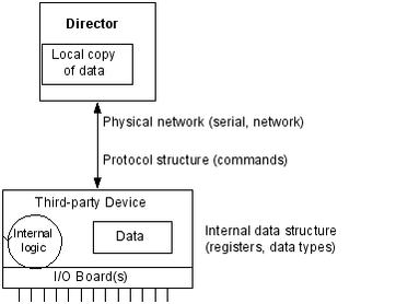
The RediGate must connect to the device (PLC, RTU, data concentrator) using some physical network – this might be over a network or a local serial port. It must send requests to the device using its native communication protocol and must request certain types of data from specified internal memory locations (registers) in the device. Once the RediGate retrieves the data from the third-party device, it stores a local copy in its internal Real-Time Databases (RTDB). From that point, other processes can use or re-transmit the data, or other host systems can request data from the RediGate.
Master/Slave Channel Functional Elements
In order for the RediGate to retrieve data from the device, the ACE configuration must include the following elements as a minimum:
- Master Channel: Defines polling sequence and timing
- Circuit: Defines which physical port to use for the connection
- Field Unit: Specifies what protocol to use and which registers to poll. Note that different Field Unit types are used depending on the third-party device protocol.
- RTDB: Defines a data area inside the RediGate in which to store data obtained from the device
In addition, the RediGate can be defined as a slave device to another master, allowing the other master to retrieve data that has been stored in the RTDB data areas. This requires one or more sets of Slave Channel elements to also be defined:
- Slave Channel: Defines slave address and protocol type used in communication to another master device.
- Slave Attach: Defines which RTDB contains data that will be made available to the master on this unit's slave address.
The normal polling sequence is as follows (numbers refer to the elements in the following diagram):
- The Master Channel generates a poll request based on its Scan Table. The Master Channel simply scans devices by address, but is not dependent on any specific communication protocol
- The Protocol Task (Field Unit definition) looks up the requested poll in its Poll Table and sends the defined command to the external device in the correct protocol format.
- The response from the device is processed and validated
- The device data is then stored into the RTDB defined for that Field Unit. This polling cycle continues based on the timing and sequence defined in the ACE configuration for the Master Channel. The RTDB typically only contains the last known value for each data point in its register locations (there are some cases where the protocol is capable of supporting event-based data).
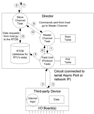
When an external master device requests data from the Slave Channel, the following sequence is observed:
- The master request is received by the Slave Channel for certain registers in the RTDB.
- The Slave Channel requests the latest value stored in these registers from the RTDB. Note that the external device is not polled directly to request data at this time, only the stored copy of last-known data in the RTDB.
- The RTDB returns data to the Slave Channel, which then returns the data to that master that requested it.
If the host sends a command via the Slave Channel to set certain register values in the device, the following sequence is observed. Note that in this case the command is typically sent on a pass-through basis directly to the device, different from the previous sequence where data is requested from the RTDB:
- The host command message is received by the Slave Channel (5), which is passed internally from the Slave Channel to the Master Channel task. The Master Channel, in turn, sends the request to the Field Unit protocol task (1), which sends a poll to the field unit (2), and waits for a valid response from the device (3).
- After receiving the response, the Field Unit protocol task notifies the Master Channel of the command's success or an invalid response. No notification is given if the command times out.
- The Master Channel passes the success or failure notification to the Slave Channel, and the Slave Channel notifies the host (7).
Note that in the foregoing command sequence, no data is returned from the Field Unit to the RTDB. If the command sent from the master included writing data to the third-party device, that data is written directly to the device and does not exist in the RTDB unless a subsequent Master Channel polling process subsequently requests it, as described above in steps 1-4.
ISaGRAF Channel Functional Elements
One of the features in the RediGate is the ability to define an ISaGRAF internal logic device (PLC) that operates as a stand-alone device within the system.
The Channel/RTU structure described in the previous section is very similar to the structure used for the ISaGRAF field unit. In this case, the RediGate uses an "Internal Channel" to communicate with the ISaGRAF field unit, whereas the Master Channel is used to communicate externally to other devices.
An ISaGRAF Field Unit may be thought of as a "virtual RTU". It is "virtual" because it doesn't exist as a separate device, but rather it resides inside the RediGate. As in the case of an external RTU, this ISaGRAF "virtual RTU" may contain I/O boards connected to field wiring, and may include programming logic. This is diagrammed below. 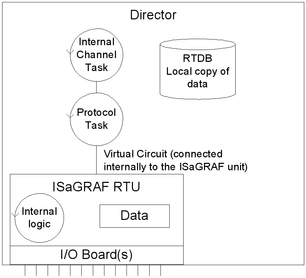
In order to preserve a logical consistency between the ISaGRAF channel and other Master Channels, an analogous structure of ACE objects is used for the Internal Channel.
Master Channel Structure | Internal Channel Structure (ISaGRAF) |
Master Channel: Defines polling sequence and timing to external devices | Internal Channel: Defines polling sequence and timing to internal |
Circuit: Defines which physical port to use for the connection (Async or Network) | Virtual Circuit: Defines a logical port to use for internal connection to ISaGRAF unit |
Field Unit: Specifies what protocol to use and which registers to poll. Note that different Field Unit definitions are used depending on the third-party device protocol. | ISaGRAF Field Unit: Specifies a specific type of field unit definition for the ISaGRAF unit, as well as which registers to poll. |
RTDB: Defines a data area in which to store data obtained from the device | RTDB: Defines data area in which to store data obtained from the ISaGRAF unit. Note that this is different from data stored internally within the ISaGRAF logic device. The RTDB is necessary if ISaGRAF data is to be used externally by other master systems or the HCP. |
In the case of a Master Channel, there are two locations where the data is stored. The external Field Unit contains certain data that are accessed using a protocol request. The RediGate contains an RTDB, which includes only the points of data obtained using the Master Channel polling.
For the ISaGRAF RTU the situation is analogous. One set of data resides inside the ISaGRAF RTU logic device and may contain any number of internal values. But only the data polled from ISaGRAF using the Internal Channel is available within the RTDB, which may be made available to other systems.
The data flow diagram for the ISaGRAF unit is shown below. Compare this with the data flow diagram for an external device (RediGate Configuration Manual#Master/Slave Channel Functional Elements).
- The Internal Channel generates a poll request based on its Scan Table.
- The ISaGRAF Protocol task (Field Unit definition) looks up the requested poll in its Poll Table and sends the defined command to the internal ISaGRAF RTU.
- The response from ISaGRAF is processed and validated
- The ISaGRAF data is then stored into the RTDB. This polling cycle continues based on the timing and sequence defined in the ACE configuration for the Internal Channel. The RTDB typically only contains the last known value for each data point in its register locations.
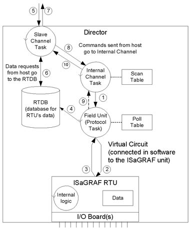
When an external master device requests data using the Slave Channel, the following sequence is observed:
- The master request is received by the Slave Channel for certain registers in the RTDB.
- The Slave Channel requests the latest value stored in these registers from the RTDB. Note that when using a generic master device, the ISaGRAF device is not polled directly to request data at this time, only the last-known value stored in the RTDB.
- The RTDB returns data to the Slave Channel, which then returns the data to that master that requested it.
If the host sends a command to the Slave Channel for ISaGRAF, the following sequence is observed. Note that in this case the command is typically sent on a pass-through basis directly to ISaGRAF, different from the previous sequence where data is requested from the RTDB:
- The host command message is received by the Slave Channel (5), which is passed internally from the Slave Channel to the Internal Channel task. The Internal Channel, in turn, sends the request to the ISaGRAF Field Unit protocol task (1), which sends a poll to the internal RTU (2), and waits for a valid response (3).
- After receiving the response, the ISaGRAF Field Unit protocol task notifies the Internal Channel of the command's success or an invalid response. No notification is given if the command times out.
- The Internal Channel passes the success or failure notification to the Slave Channel, and the Slave Channel notifies the host (7).
The ISaGRAF Workbench is one type of master that may be used with the ISaGRAF RTU. The Workbench issues special protocol messages which are passed to ISaGRAF, allowing the system designer to examine ISaGRAF internal registers, troubleshoot operation of the program, download a new ISaGRAF logic program, etc. The ISaGRAF Workbench must connect to the ISaGRAF RTU through a Slave Channel as described above in order to gain this special access to the ISaGRAF logic processing functionality. See the Elecsys ISaGRAF Manual for more information on using and programming the ISaGRAF RTU.
Other Internal Channel Functional Elements
In addition to the special handling of the internal ISaGRAF RTU, the Internal Channel includes other child elements that provide special features within the system. These are the Virtual RTU, Status RTU, Segment RTU, and Internal Master. These are all connected to the Internal Channel using a "Null Circuit," which is simply a placeholder to preserve the normal Channel-Circuit-Field Unit structure. These types of field units are briefly explained here.
The Virtual RTU provides a data repository (RTDB) for internal storage of data, which is not connected with any external field device or ISaGRAF unit. 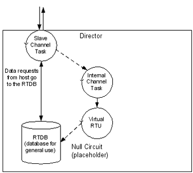
The Status RTU is another type of Virtual RTU, that can be used for storing data, but it has an additional purpose. When the RediGate is configured to poll one or more Field Devices using one or more Master Channels, there is some status information for each device such as poll count, current failed/good communication status, etc. These statistics for a whole set of Field Devices may be stored in the Modbus 40,xxx registers in the Status RTU, if desired, allowing a host system to manage communication statuses for all the field units in one place. See the section RediGate Configuration Manual#Communication Status Registers for more information on field unit status values.
The Segment RTU is another type of Virtual RTU, which allows for a more flexible structure of data. Most Real-time Databases (RTDB) have a structure something like this (exact point types and count are configurable):
Data type | Register addresses |
Boolean | 00,001 – 00,100 |
Boolean | 10,001 – 10,100 |
UINT16 | 30,001 – 30,100 |
UINT16 | 40,001 – 40,100 |
UINT32 | 41,001 – 41,100 |
The Segment RTU allows a more heterogeneous mix of register types and point counts. Rather than large "segments" of single data types (Boolean, UINT16) as listed above for a normal RTDB, the Segment RTU allows a flexible definition such as:
Segment RTDB Instance | Register type / Count |
1 | UINT8 2 |
2 | UINT325 |
And finally, the Internal Master is a virtual RTU/RTDB definition that has the special property of being able to consolidate data from any other RTDB databases. Normally, an RTDB under any Field Unit definition only contains the data polled from that device defined in the Field Unit. The Internal Master allows one or more RTDB locations to be defined and populated with a copy of certain data points from other RTDB's. Because the RTDB is used to present data to an external master device using a Slave Channel or HCP communication link, this allows data subsets to be created.
Clients Object Placeholder
![]()
![]()
The Clients object is a placeholder for graphical clarity on the ACE tool, and provides a location to add client tasks to the configuration. Clients are generally tasks where the RediGate is initiating a connection "to" something else, such as to a field device or a network service.
| Attributes | Function |
|---|---|
| Object Type | Clients |
| Parent(s) | System |
| Instance | Must be 0 |
Master Channels Placeholder
![]()
![]()
The Master Channels Identifier is a placeholder for graphical clarity on the ACE tool, and provides a location to add specific Master Channels (data concentrators) to the configuration.
| Attributes | Function |
|---|---|
| Object Type | Master Channels |
| Parent(s) | System → Clients |
| Instance | Must be 0 |
Master Channel
![]()
![]()
The Master Channel configuration defines a "Scan Group" to a collection of field units that may be over one of the available serial or network circuits. The Master Channel defines how each field unit is scanned over the network, and is independent of which protocols are being used on individual field units.
| Attributes | Function |
|---|---|
| Object Type | Master Channel |
| Parent(s) | System → Clients → Master Channels |
| Instance | 0 to 15 (typically 15 is reserved for Internal Channels |
The Master Channel must have at least one child Circuit object defined (Async or Network).
| Properties | Values |
|---|---|
| Name | Enter the Master Channel name. This is the name which appears in the user diagnostics menu, and is also see in an HCP diagnostic window if used with Elecsys HCP. |
| Channel Type | In some configurations this may be listed as "Direct Master", which includes a few operational differences noted below. The main differences between the Channel Types are listed below: Direct Master
Direct Master Flex Scan
|
| Auto Start | Select the automatic polling method for the channel. Automatic polling types supported are:
|
| Response Timeout | Enter the response timeout in milliseconds. Time in milliseconds to wait for a poll response before declaring the message failed. For Network Circuits, if a scan fails because the socket is broken or interface is unavailable, then the Master Channel protocol will wait a period of time (Response Timeout * 2) to try the next IP address in the Circuit. |
| Broadcast Delay | Unused. |
| Interpoll delay | Enter the interpoll delay in milliseconds. Use this to add a delay between each poll sent by the channel to any field unit. Time in milliseconds to wait between each poll. |
| Scan Effective Limit | The Scan Effective Limit is the time (in seconds) defining which scans in the Scan Table are considered "effective" – meaning, polls which affect the status of the Field Unit if there are poll failures. Scan Table entries which have a Scan Period greater than the Scan Effective Limit do not mark the Field Unit offline when the scan fails. For instance, if the Scan Effective Limit is configured for 30 seconds, then any scans defined with Scan Period <= 30 will be used to mark the Field unit online or offline. Scans with Scan Period greater than 30 will not mark the Field Unit offline even if they fail. The Scan Effective Limit only applies to the "Direct Master Flex Scan Table" version of the channel object. A Scan Effective Limit of 0 disables this feature, thus all polls will affect the Field Unit status. |
| Network Recovery | Enter the network recovery period in seconds. Time period to wait after an RTU fails, before attempting to re-establish communications with that RTU. This will take the device off scan, allowing other devices on the channel to be polled more frequently and not waste as much time retrying a failed device. |
| Scan Table | Click the Edit Table button to define the order and selection of polls to be sent to all field units on this channel, independent of protocol. Field Unit configurations (Modbus, etc.) define the protocol-specific nature of the individual polls that are sent. Only one Unit Address/Poll Record combination can be entered in the Scan Table. Any subsequent table entries with duplicate Unit Address/Poll Record will be ignored. Scan Table details: Unit Address - This is the Field Unit Address as configured in each field unit on this Channel. (To force the Scan Table to ignore the Scan Period, enter a Scan Table row with the Unit Address of -1.) Poll Record - This is the row number in the Poll Record in the Field Unit definition. The first row in a Poll Table is referenced as record 1. Only those polls which are to be polled continuously need to be listed in this Scan Table. Scan Period - Enter the scan period in seconds. The Scan Period is the amount of time to use for scheduling each scan (global for all scans in the Direct Master, or configured per scan row in the Direct Master Flex Scan Table). For the Direct Master, the channel will restart the scan table sequence after the Scan Period has expired. If the total time for a given channel exceeds the scan period, the next scan shall be scheduled immediately. For the Direct Master Flex Scan Table, each poll is scheduled based on its own Scan Period. If the total time required for scans at any point is greater than allowed by the Scan Periods, the scans will operate as fast as possible. Setting a Scan Period to a negative number will disable a scan. However, the first entry in the Scan Table for each Unit Address should not be disabled, or it may not correctly set the Alive/Dead status of the unit. Comment - Optional column, allowing a descriptive comment to be entered for each row in the table. The Comment field is unused in the configuration. |
Async Circuit
![]()
![]()
An Async Circuit is a serial communications path to one or more field units from a common Master Channel, using an Async serial port. The Async Circuit allows for redundant serial ports to a common set of field units, such as a Primary and Secondary radio or modem communication path.
You should generally use a single AsyncCircuit object for a single physical serial port, and include multiple FieldUnit objects under it if they are multidropped on the same serial line. (One exception to this is when mixing serial communications with a DF1 PLC and other devices, since the DF1 has a customized circuit definition.)
| Attributes | Function |
|---|---|
| Object Type | AsyncCircuit |
| Parent(s) | System → Clients → Master Channels → Master Channel |
| Instance | Must be between 0 and 16. |
The Async Circuit should have at least one Field Unit child object defined under it.
| Properties | Values |
|---|---|
| Primary Port | Select the primary physical communication port for this circuit. The selected port must be defined as an object under Networks, where its Async port properties (baud rate, etc.) are also defined (see the section 4-Master Channel#Async Port). The same port (e.g. COM1) may also be shared with certain other tasks, such as Terminal Server, and may be used with Virtual Ports. |
Network Circuit
![]()
![]()
A Network Circuit is an IP network communications path to one or more field units from a common Master Channel. The Network Circuit is used when the field unit is connected via a network, such as TCP/IP, PPP, or SLIP.
Because of the fact that the Network Circuit includes the IP address of the end device, you will generally need to use multiple Network Circuit objects under a channel, one per device. (An exception would be a bridged device that uses a single IP address but represents multiple protocol FieldUnit devices.)
Each Network Circuit represents a TCP socket connection to a device, which is made when the Master Channel initiates a poll to the device. Each socket (one or more, if configured) is kept open independently according to the Failover Delay parameter (time to live). This avoids having to open and close sockets repeatedly to the device, as long as the scan interval is less than the Failover Delay and polls are successful.
| Attributes | Function |
|---|---|
| Object Type | NetCircuit |
| Parent(s) | System → Clients → Master Channels → Master Channel |
| Instance | Must be consecutive, starting from 0 (unique among other types of circuits). The Network Circuit should have at least one Field Unit child object defined under it. |
| Properties | Values |
|---|---|
| Circuit Type | Select the circuit type as 'Network Circuit' |
| Failover Delay | Time to Live for network socket (in seconds). Make sure this is large enough to allow for the time it takes to poll on this circuit, taking into account timeouts and interpoll delays of all scans on the channel. |
| Master Network Port | Must be consecutive, starting from 0 (unique among other types of circuits). The Network Circuit should have at least one Field Unit child object defined under it. |
| Connect Table | Click the Edit Table button to edit the IP address or list of IP addresses to connect for the Field Unit(s) on this circuit. Entering multiple IP addresses will allow failover connections when one connection fails (all connections made to the same Master Network Port on different IP addresses). Destination Address Enter the IP address to connect. The IP address must be in the same IP network or reachable via the Default Gateway or Route Table configuration. Interface Enter the network interface over which to connect to this Destination Address. The network interface must match the Interface name in the ACE object (such as "Ether1") rather than the Linux interface name (such as "eth0"). |
DF1 RS-232 Async Circuit
![]()
![]()
The DF1 RS-232 Async Circuit is a special serial communications path to one or more Allen Bradley DF1 field units from a common Master Channel. Use this circuit instead of the generic Async Circuit when configuring a DF1 field unit under a Master Channel.
See the Protocol_DF1-CSP-Master protocol documentation for information on configuring the DF1 RS-232 Async Circuit and FieldUnit.
HART Circuit

The HART Circuit object is a special serial communications path for one or more HART devices from a common master channel. Use this circuit instead of the generic Async Circuit when configuring a HART device under a Master Channel.
See the Protocol_HART-Master protocol documentation for information on configuring the HART Circuit and FieldUnit.
NMEA (GPS) Field Unit
![]()
![]()
![]() The NMEA Field Unit object contains unique information for a special internal Field Unit that reads location information from an Elecsys cellular modem.
The NMEA Field Unit object contains unique information for a special internal Field Unit that reads location information from an Elecsys cellular modem.
| Attributes | Function |
|---|---|
| Object Type | FieldUnitModbus32, FieldUnitModbusTCP32 |
| Parent(s) | System → Clients → Master Channels → Master Channel → Circuit |
| Instance | Must be unique under a channel |
The NMEA Field Unit must have an RTDB child object defined under it.
| Properties | Values |
|---|---|
| Unit Name | Enter the field unit name. Unit name is displayed in diagnostic menus and in an HCP diagnostic screen. |
| Unit Address | Enter the actual field unit address which is configured in the device being polled. Valid Modbus addresses 1 to 255. |
FieldUnit - Modbus Master (and others)
![]()
![]() – Modbus SOS (Specific Outstation) poll modifications
– Modbus SOS (Specific Outstation) poll modifications


RTDB – RealTime DataBase
![]()
![]() An RTDB (Real Time DataBase) defines the size of the virtual database reserved for the Field Unit. All FieldUnit objects require a child RTDB in order to function properly, which is defined using a numeric register address format (typically, using Modbus-like addresses).
An RTDB (Real Time DataBase) defines the size of the virtual database reserved for the Field Unit. All FieldUnit objects require a child RTDB in order to function properly, which is defined using a numeric register address format (typically, using Modbus-like addresses).
| Attributes | Function |
|---|---|
| Object Type | RtdbMod |
| Parent(s) | System → Clients → Master Channels → Master Channel → Circuit → Field Unit |
| Instance | Must be 0. |
The RTDB object supports several additional optional child objects (see the sections 4-Master Channel#Deadband , 4-Master Channel#Pre-Initialized RTDB, Tag Names, 4-Master Channel#Data Blocking, and 4-Master Channel#Timestamp).
| Properties | Values |
|---|---|
| Database Definition | Click the Edit Table button to edit the details of the RTDB definition. Point Count – Enter the number of data points of this type to be allocated space in the database. Field Format – Select the point data format: Boolean – Boolean The following field formats are the same as the above but do not generate an RBE flag when the data changes, even if the Field Unit is set to Produce RBEs=Yes. No-Rbe Boolean – Boolean Data Address – Enter the address of the starting register within the RTDB for the Field Format and Count defined on this row. Comment - Optional column, allowing a descriptive comment to be entered for each row in the table. The Comment field is unused in the configuration. |
Deadband
![]()
![]() A Deadband object defines deadbands for the data fields configured within a Real-time Database (RTDB). This is only used to reduce the communications traffic on an RBE (Report by Exception) connection. If no RBE connection is configured, an RTDB does not require a Deadband object.
A Deadband object defines deadbands for the data fields configured within a Real-time Database (RTDB). This is only used to reduce the communications traffic on an RBE (Report by Exception) connection. If no RBE connection is configured, an RTDB does not require a Deadband object.
The way the deadband works is that when a poll occurs and data is received from a Field Unit, if there is a Deadband defined for any of the points included in the poll, the current value in the RTDB is checked first. If the new values are not changed from the existing RTDB values by an amount greater than the deadband, the values are discarded and not stored in the RTDB.
| Attributes | Function |
|---|---|
| Object Type | LinuxDeadband |
| Parent(s) | System → Clients → Master Channels → Master Channel → Circuit → Field Unit → RTDB |
| Instance | Must be 0 |
| Properties | Values |
|---|---|
| Deadband | Click the Edit Table button and add as many rows as necessary to define the desired deadband values for the points in the RTDB.
|
For example, let's say the RTDB is configured with the following fields:
Point Count | Type | Data address | |
Field 1: | 100 | Boolean | 1 |
Field 2: | 100 | Boolean | 10001 |
Field 3: | 100 | UINT16 | 30001 |
Field 4: | 100 | UINT32 | 40001 |
The first four analogs at address 30,001 are 12-bit analogs that change from 0 to 4095, and we want to deadband them to report as RBE only when their values change more than 5% of their range (205). The 3rd and 4th analogs in the range starting at 40,001 we want to throttle their RBE reports to only change when the values increase or decrease by 100 and 500, respectively. All other points will be allowed to report as RBE with any single change positive or negative in their values. For this example, the Deadband table will be defined as follows:
Field | Offset | Count | Deadband | Explanation |
3 | 0 | 4 | 205 | Deadband for 30,001-30,004, 5% of its range |
4 | 2 | 1 | 100 | Deadband for 40,003 |
4 | 3 | 1 | 500 | Deadband for 40,004 |
Pre-Initialized RTDB
![]()
![]() Ordinarily, all RTDB database locations are initialized to zero values upon system startup (or zero-length strings). However, sometimes it may be desired to initialize certain database locations to a non-zero value, before any polling or other data operation occurs. Each RTDB has an optional ACE object that allows one or more registers to be initialized at startup.
Ordinarily, all RTDB database locations are initialized to zero values upon system startup (or zero-length strings). However, sometimes it may be desired to initialize certain database locations to a non-zero value, before any polling or other data operation occurs. Each RTDB has an optional ACE object that allows one or more registers to be initialized at startup.
| Attributes | Function |
|---|---|
| Object Type | PreInitRtdb |
| Parent(s) | System → Clients → Master Channels → Master Channel → Circuit → Field Unit → RTDB |
| Instance | Must be 0 |
| Properties | Values |
|---|---|
| Init Values | Click the Edit Table button to define any pre-initialized RTDB values.
|
Tag Names
![]()
![]()
RTDB database locations are configured using numeric address locations. However, the optional Tag Names child object under the RTDB allows one or more numeric address to be associated with an ASCII tag. This may be used for publishing data by tag using MQTT, for internal display using Custom Reports, and they may be used for other purposes.
| Attributes | Function |
|---|---|
| Object Type | TagNames |
| Parent(s) | System → Clients → Master Channels → Master Channel → Circuit → Field Unit → RTDB |
| Instance | Must be 0 |
| Properties | Values |
|---|---|
| Init Values | Click the Edit Table button to define any RTDB tags.
|
When publishing to MQTT, data values are published with corresponding tag name, if configured in ACE, with some exceptions (substitutions) noted below.
With MQ-RBE, Sparkplug-B, or MQ-JSON:
- If tag name includes a space, the space will be converted to an underscore _ character instead.
- The space-to-underscore conversion also applies to the Ethernet/IP master protocol.
With MQ-RBE or Sparkplug-B (not JSON):
- If tag name includes a period . it's tag will be published with a forward slash / instead.
- If tag name includes an integer between square brackets for an array (such as [23] ), it's tag will be published with the integer surrounded by forward slash and underscore instead (such as /23_ ).
- In Ignition, the forward slash in a published tag name creates a level in the collapsible tag hierarchy.
Data Blocking
![]()
![]()
The Data Blocking object allows groups of RTDB points to be blocked together for exception reporting (RBE) to an HCP. If any one point in the defined Data Block changes, all the points are reported, including the unchanged ones. If no data blocking capability is required, this object is optional.
Although it is normally recommended to store 32-bit data into 32-bit registers, Data Blocking could be used if a configuration requires 32-bit data to be stored in pairs of 16-bit registers. Each pair of registers could be defined in a separate row (count of 2), and if either value changes, the Data Block will force both registers in the pair to be reported together.
| Attributes | Function |
|---|---|
| Object Type | |
| Parent(s) | System → Clients → Master Channels → Master Channel → Circuit → Field Unit → RTDB |
| Instance | Must be 0 |
| Properties | Values |
|---|---|
| Block Definition | Click the Edit Table button to add as many rows as necessary to define the Data Block capability.
|
| Parent(s) | System → Clients → Master Channels → Master Channel → Field Unit → RTDB |
| Instance | Must be 0 |
Data Blocking does not work properly if you are using Pre-Initialized registers on the same RTDB. Blocks will be broken up at the boundaries of pre-initialized registers.
Data Blocking does not work if the blocks span discontiguous (non-sequential) register addresses in the RTDB.
Linux Timestamp
![]()
![]() A Timestamp object is used to store the time and date at which data is polled by a Master Channel. The timestamp is stored in register(s) within the RTDB, and thus may itself be reported with the RBE packet or polled via a Slave Channel.
A Timestamp object is used to store the time and date at which data is polled by a Master Channel. The timestamp is stored in register(s) within the RTDB, and thus may itself be reported with the RBE packet or polled via a Slave Channel.
Timestamps may be stored in one of two conditions whenever a specified poll occurs:
- "Always" = store timestamp whenever a poll for data occurs, even if nothing is stored in the RTDB because deadband values have not been exceeded.
- "Post-Deadband" = store timestamp only when one or more data points is stored into the database. If Deadbands are configured, data is not stored into the database until the difference between the old value and new value exceeds the configured deadband.
| Attributes | Function |
|---|---|
| Object Type | LinuxTimeStamp |
| Parent(s) | System → Clients → Master Channels → Master Channel → Circuit → Field Unit → RTDB |
| Instance | Must be 0 |
| Properties | Values |
|---|---|
| Reserved | Unused field |
| Timestamp | Click the Edit Table button to add as many rows as necessary to define the Timestamp operation. Poll Number – Enter the row number of the poll defined in the unit's Poll Table. Whenever this poll occurs for the defined points (or when any changed data points are stored in the RTDB field), a timestamp is also stored. Poll numbers start at 1. Stamp Address – Register address within the RTDB for this Field Unit in which to store the timestamp value for this poll. The Stamp Address should be the first of one or more registers with a UINT16 or UINT32 data type, and must be defined in the RTDB with the correct quantity and type. Make sure that each register or registers occupied by the timestamp are not overwritten by any other data value to avoid conflicting data. Stamp Format – Data format to use when storing data into the specified register (UINT16 or UINT32). The Stamp Format should be chosen appropriately to match the Stamp Type (below), and the data type of the RTDB register. UINT24 or UINT32 data types should be stored into a UINT32 RTDB register.
Stamp Type – Format in which to store the timestamp.
Comment - Optional column, allowing a descriptive comment to be entered for each row in the table. The Comment field is unused in the configuration. |
Internal Channel
![]()
![]() The Internal Channel configuration defines virtual field units that have several special internal purposes, including an ISaGRAF Field Unit, Status Field Unit, Virtual RTU, Segment field unit, or Internal Master. The Internal Channel configuration and its 'child' objects are similar in structure to the Master Channel and its 'child' objects, but they refer to internal databases rather than external devices being polled by a communication protocol.
The Internal Channel configuration defines virtual field units that have several special internal purposes, including an ISaGRAF Field Unit, Status Field Unit, Virtual RTU, Segment field unit, or Internal Master. The Internal Channel configuration and its 'child' objects are similar in structure to the Master Channel and its 'child' objects, but they refer to internal databases rather than external devices being polled by a communication protocol.
| Attributes | Function |
|---|---|
| Object Type | Internal Channel |
| Parent(s) | System → Clients → Master Channels |
| Instance | 0 to 15 (typically 15 is reserved for the Internal Channel, but instance 14 might also be used if a second ISaGRAF RTU is included) The Internal Channel must have at least Circuit child object defined under it. The Database Flush (DumpRTDB) object is an optional child under Internal Master. |
| Properties | Values |
|---|---|
| Name | Enter the Internal Channel name. This is the name which appears in the MMI when viewing diagnostics. |
| Channel Type | In some configurations this may be listed as "Internal Channel", which includes a few operational differences noted below. The main differences between the Channel Types are listed below: Internal Channel
Internal Channel Flex Scan
|
| Auto Start | Select from the drop down menu the automatic polling required. Automatic polling types supported are:
|
| Response Timeout | Enter the response timeout in milliseconds. This should normally be 32767 for the Internal Channel. |
| Broadcast Delay | Enter the broadcast delay in milliseconds. Delay in milliseconds after a command is sent to the ISaGRAF RTU, before normal polling resumes. |
| Interpoll Delay | Enter the interpoll delay in milliseconds. Use this to add a delay between each poll sent by the channel to the ISaGRAF unit. Time in milliseconds to wait between each poll. |
| Scan Effective Limit | The Scan Effective Limit is the time (in seconds) defining which scans in the Scan Table are considered "effective" – meaning, polls which affect the status of the field unit if there are poll failures. Scan Table entries which have a Scan Period greater than the Scan Effective Limit do not mark the Field Unit offline when the scan fails. For instance, if the Scan Effective Limit is configured for 30 seconds, then any scans defined with Scan Period <= 30 will be used to mark the Field unit online or offline. Scans with Scan Period greater than 30 will not mark the Field Unit offline even if they fail. The Scan Effective Limit only applies to the "Internal Channel Flex Scan Table" version of the channel object. |
| Network Recovery | Enter the network recovery period in seconds. Time period to wait after an RTU fails, before attempting to re-establish communications with that RTU. |
| Scan Table | Click the Edit Table button to define the order and selection of polls to be sent to the ISaGRAF Field unit on this channel. Unit Address - Enter the Modbus address of the ISaGRAF field unit to be polled. (To force the Scan Table to ignore the Scan Period, enter a Scan Table row with the unit address of -1.) Poll Record - This is the row number in the Poll Record for each poll defined for the ISaGRAF unit. The first row in a Poll Table is referenced as record 1. Only those polls which are to be scanned continuously need to be listed in this Scan Table. Scan Period - Enter the scan period in seconds. The Scan Period is the amount of time to use for scheduling each scan (global for all scans in the Internal Channel, or configured per scan in the Internal Channel Flex Scan Table). Comment - Optional column, allowing a descriptive comment to be entered for each row in the table. The Comment field is unused in the configuration. |
Do you need a Scan Table? The Internal Channel Scan Table is similar to the Master Channel, but it only refers to polls to the ISaGRAF RTU. In some cases it may not be necessary to include scans to read the ISaGRAF data. To explain why, it is necessary to examine the relationship between the ISaGRAF RTU and the RTDB.
The ISaGRAF RTU (logic, I/O, and data) exists as a separate task inside the RediGate. Similar to an external RTU, the ISaGRAF RTU contains data. In order to get this data into an RTDB, it must be scanned by the Scan Table – even though it resides inside the same hardware. The reason for this is to have a consistent Channel structure for all RTUs. For a more complete explanation, see the section 5-Internal Channel#ISaGRAF Channel Functional Elements.
If the ISaGRAF RTU does not contain data that is necessary to store in an RTDB, then it is not necessary to define any polls to the ISaGRAF RTU. As one example, the ISaGRAF logic may be written with special ISaGRAF functions such as DMOV or ISAMOV to move data from ISaGRAF or an RTDB, or from one RTDB into another. Or, the ISaGRAF logic may simply act on data from other RTDB's, such as sending a Publish message or an E-mail. In these cases, the data contained within the ISaGRAF RTU may not need to be scanned by the Internal Channel in order to read it into the ISaGRAF RTDB, and thus no Scan Table rows need to be defined.
Also note that other units under the Internal Channel (Status RTU, Virtual RTU, Segment RTU) do not need to be polled for data. They reside under the Null Circuit, and their data simply appears in their own RTDBs automatically without being scanned.
Null Circuit
![]()
![]()
A Null Circuit object defines placeholder in the configuration, under which one or more Status/Control, Virtual, Segment, or Internal Master field units are defined for an Internal Channel.
| Attributes | Function |
|---|---|
| Object Type | NullCircuit |
| Parent(s) | System → Clients → Master Channels → Internal Channel |
| Instance | Must be 0 or 1. (However, the Virtual Circuit must be instance 0, so if used with a Null Circuit, the Null Circuit must be instance 1.) |
The Null Circuit should have at least one child Filed Unit object defined under it.
| Properties | Values |
|---|---|
| Circuit Type | Placeholder for the circuit type as 'Null Circuit'. |
Virtual Field Unit
![]()
![]()
A Virtual Field Unit object allows an additional Real-time Database (RTDB) to be defined for internal storage of data. This may be used as a data repository for the ISaGRAF program logic to store data values, and/or the RTDB may serve as the source of data for a Slave Channel definition.
Note: The Virtual Field Unit will not automatically be marked alive for purposes of reporting via an MQTT client. To make sure the Virtual Field Unit is marked alive, one of the following needs to be done:
- In the Internal Master Channel, define one scan for the Virtual unit (use Poll Record 1). Make sure the Scan Period is very long (longer than the Scan Effective Limit). Even though the poll will be marked as a timeout, the Virtual Unit will be marked alive because the Scan Table completes its cycle.
- In the Internal Master Channel, if there is an Internal Master unit being scanned in addition to the Virtual unit, the Virtual unit will also be marked as alive. (This occurs because the Channel is required to complete one full scan cycle successfully.)
- Or you could use a POD "SET RTU STATUS" or ISaGRAF 'setosval' function to set the Virtual unit to an alive state.
| Attributes | Function |
|---|---|
| Object Type | FieldUnitVirtual |
| Parent(s) | System → Clients → Master Channels → Internal Channel → NullCircuit |
| Instance | Must be between 0 and 255, and should be unique under this Null Circuit among all Status, Virtual, and Internal Master field units. |
| Properties | Values |
|---|---|
| Unit Name | Enter the field unit name as an identifier for the Field Unit. |
| Unit Address | Enter the Field Unit address. This should be a unique address from any other ISaGRAF, Status, or Internal Master field unit addresses on this Internal Channel. The default address is 3. |
| Protocol | Placeholder for field unit protocol type 'Repository Database Unit'. |
| Com Retries | This parameter is a null field to retain compatibility with other field unit objects. The only option is 'N/A'. |
| Comm Status Holdreg | Enter the starting holding register to contain the communication status for this field unit. Typically, this field is unused for the Virtual Unit. Each Comm Status takes 5 registers, beginning at the register configured in this parameter. The Comm Status Holdreg for each field unit in a configuration must be defined such that the five registers do not overlap other registers being used. If the register is defined in the 30,xxx address range, the status values will be stored in the local device's RTDB (i.e., the RTDB defined as a child object to this ISaGRAF Field Unit. If the register is in the 40,xxx range, the values will be stored in the Status/Control Field Unit RTDB. The Comm Status Holdreg is optional, and can be set to 0 to disable the storage of status registers. See the section 5-Internal Channel#Communication Status Registers, for a description of the five Comm Status Register contents. |
| Produce RBEs | Select this option to determine whether to produce a Report by Exception (RBE) flag when data in this unit's RTDB changes. In the RTDB, for every data point, there are potentially 4 RBE flags associated with every data point. When the data point changes, the RBE flags are set. These flags are used to determine when new data needs to be reported to the HCP. |
| No Polls | This parameter is a null field to retain compatibility with other field unit objects. The only option is 'N/A'. |
Internal Master Field Unit
![]()
![]()
The Internal Master is a special type of Field Unit which is designed to provide an easy mechanism for collecting and consolidating data from any other Field Unit RTDBs into the RTDB associated with the Internal Master unit. In theory, it operates like a Master Channel Field Unit, which polls data from an external device; but the Internal Master operates only to take data from one RTDB to another.
| Attributes | Function |
|---|---|
| Object Type | FieldUnitInternalMast |
| Parent(s) | System → Clients → Master Channels → Internal Channel → NullCircuit |
| Instance | Must be between 0 and 256, and should be unique under this Null Circuit among all Status, Virtual, and Internal Master field units. The Internal Master Field Unit should have a 5-Internal Channel#Modbus RTDB child object defined under it (see page ). |
| Properties | Values |
|---|---|
| Unit Name | Enter the field unit name. |
| Unit Address | Enter the field unit address. This should be a unique address from any other ISaGRAF, Status, Virtual, or Internal Master field unit addresses on the Internal Channel. The default address is 5. |
| Protocol | Select the Protocol type for the Internal Master field unit. The Protocol selection determines the rules by which a host can access the data in this Virtual Master's RTDB, via attachment to a Slave Channel. Available Protocol types are:
|
| Com Retries | Enter the number of communication retries after a failed poll attempt. If a poll attempt fails, poll will be sent again up to the configured number of "Com Retries" before the field unit is declared failed. |
| Comm Status Holdreg | Enter the starting holding register to contain the communication status for this field unit. Each Comm Status takes 5 registers, beginning at the register configured in this parameter. The Comm Status Holdreg for each field unit in a configuration must be defined such that the five registers do not overlap other registers being used. If the register is defined in the 30,xxx address range, the status values will be stored in the local device's RTDB (i.e., the RTDB defined as a child to this Field unit). If the register is in the 40,xxx range, the values will be stored in the Status/Control Field Unit RTDB. The Comm Status Holdreg is optional, and can be set to 0 to disable the storage of status registers. See the section 5-Internal Channel#Communication Status Registers, for a description of the five Comm Status Register contents. |
| Produce RBEs | Select this option to determine whether to produce a Report by Exception (RBE) flag when data in this unit's RTDB changes. In the RTDB, for every data point, there are potentially 4 RBE flags associated with every data point. When the data point changes, the RBE flags are set. These flags are used to determine when new data needs to be reported to the HCP. |
| Poll Table | Click the Edit Table button to define the Modbus polls to be sent to this unit. Note that the Poll Table only defines how the Modbus protocol is defined to operate for each set of data defined in the polls. The Poll Table doesn't actually do any of the polling itself. If you want any of these polls to be sent to the Field Unit on a regular basis, it should be referenced in one or more Scan Table entries in the Master Channel. Src Chan – Enter the Channel number of the RTDB containing the source data. This is either a Master Channel or Internal Channel instance number that must be defined under the Master Channels placeholder. Src RTU – Enter the Field Unit number of the RTDB containing the source data. This is the Unit Address configured in the properties of the field unit, not the instance number of the field unit ACE object, if they are different. Src Data – Enter the source register number for the starting register in the Field Unit's RTDB to begin retrieving data. Src Type - Enter the data type of the data being requested. See below for a discussion of Src Type options in the Master Channel. Src Count – Enter the number of registers to retrieve. The maximum number allowed in any poll is the same as for Modbus polls: 500 Boolean registers, 125 registers of 16-bit type, or 62 registers of 32-bit type. The Count includes the number of register values being requested, starting at the Src Data register. Dest Data – Enter the starting destination register within this Internal Master's RTDB to place the polled data. Ensure that there is a large enough quantity of registers in the RTDB to store the count. The destination register type should be chosen based on the Source Format of the data. Booleans should be stored into Boolean RTDB registers. 16-bit values should be stored into 16-bit RTDB registers. 32-bit values or 16-bit pair values should be stored into 32-bit RTDB registers. |
Discussion on Source Type
Several Src Type options are provided in the Internal Master Field Unit. These provide a number of unique capabilities for copying and transforming data from one RTDB location to another.
The following table gives a list of the Internal Master Src Type options, and an explanation of how they are used.
Src Type | Source data | Dest data | Meaning |
|---|---|---|---|
Boolean | Boolean | Boolean | Single on/off bit occupies a register |
8 bit | Take lower 16-bits of an integer register. | ||
16 bit | 16 bit | 16 bit | Typical 16-bit register type. |
24 bit | 32-bit | 32-bit | Take lower 3 bytes of a 32-bit integer register |
32 bit | 32 bit | 32 bit | |
Short String | STRING32 | STRING32 | |
Long String | STRING256 | STRING256 | |
UTF String | |||
Event | |||
Double-Float | 64 bit | 64 bit | |
Copy 16-Bit pairs into 32-Bit Regs | 16 bit | 32 bit | Registers are taken as pairs, and the Src Count should be the numbers of pairs of registers (32-bit entities). (Source registers are little-endian.) |
Swap 16-Bit pairs into 32-Bit Regs | 16 bit | 32 bit | Registers are taken pairs, and the Src Count should be the numbers of pairs of registers (32-bit entities). (Source registers are big-endian.) |
Split-Copy 32-bit Regs into 16-bit-Pair Regs | 32 bit | 16 bit | 32-bit register is broken into pairs of 16-bit registers |
Split-Swap 32-bit Regs into 16-bit-Pair Regs | 32 bit | 16 bit | same as above, but swapped |
Boolean-Src to 16-Bit-Dest Hi to Lo Bits | Boolean | 16 bit | Boolean source registers are taken in groups of 16, with the first register becoming the most-significant bit (MSB) in the 16-bit value. NOTE: writing to the 16-bit analog register is not supported. |
16-Bit-Src to Boolean-Dest Hi to Lo Bits | 16 bit | Boolean | 16 bits in source register(s) are placed sequentially to Boolean registers, in the order of most-significant bit (MSB=1st destination register) to least-significant bit in each 16-bit word. For both Boolean-Bit data types, writing to individual RTDB Boolean registers is not supported -- any bit which is written individually will set only that bit and clear all the others. |
16-Bit-Src to Boolean-Dest Lo to Hi Bits | 16 bit | Boolean | 16 bits in source register(s) are placed sequentially to Boolean registers, in the order of least-significant bit (LSB=1st destination register) to most-significant bit in each 16-bit word. |
Note that the Boolean-Bit and Bit-Boolean data type conversions support multiple quantities of 16-bit registers, but do not support 32-bit registers.
The following source types reverse the direction of data from the other types listed above, allowing data to be copied from the Internal Master RTDB to a different Field Unit's RTDB location. Be sure to keep in mind that for these data types, the "Src" (source) and "Dest" (destination) data locations are reversed. Thus:
Src Chan/RTU/Data are the destination locations to store data in the other Field Unit.
Dest Data is the source RTDB location in the Internal Master field unit.
The source and destination data types should be the same.
Src Type | Meaning |
Trigger Move Data from Local to Src Data | Choose this option to copy data from the Internal Master RTDB (Dest Data location) into another RTDB (Src Data location), based on a trigger value. The Trigger register is the last register in the specified set. |
Trigger Write Data from Local Data to Src Chan/RTU | Choose this option to write data from the Internal Master RTDB to a device on a Source Channel/RTU address, based on a trigger value. The Trigger register is the last register in the specified set. |
Always Move Data from Local to Src Data | Choose this option to constantly copy data from the Internal Master RTDB (Dest Data location) into another RTDB (Src Data location). No trigger register is used. |
Always Write Data from Local Data to Src Chan/RTU | Choose this option to constantly write data from the Internal Master RTDB (Dest Data location) to a device on a Source Channel/RTU address/Src Data register whenever this poll is scanned by the Internal Master Channel. No trigger register is used. |
The final Internal Master "Source Type" is a special function that tells the Internal Master process to run a POD logic routine. This POD program is run in the sequence of the scans that are triggered by the Internal Master. The POD program must complete before the Scan Table can move on to the next scan.
Run POD | [ Src Count ] Src Count Column value is Pod_Index. Each POD has a unique instance number, and when this Poll Table entry is trigged, the numbered POD routine runs in its entirety before control is returned to the Internal Channel for running subsequent polls. |
The POD object in the ACE configuration holds a set of programming instructions which can be used to manipulate or make decisions on data stored in RTDBs. Up to 9999 POD modules can be configured per Internal Master Channel, which are called by a Poll Table of an Internal Master RTU (which in turn is triggered by a Scan Table entry in the Internal Master Channel).
Status Field Unit
![]()
![]()
A Status Field Unit object may be used to contain unique information for internal communication diagnostics. Field units defined under Master Channels and the ISaGRAF field unit contain a parameter for storing communication status (Comm Status Register). If the Comm Status Register for any Field Unit is configured with a starting address in the 40,xxx address range, its status values are stored in the RTDB defined for this Status Field Unit. This allows all communication status information to be stored in one place, if desired in the system design.
However, if the Comm Status Register for any Field Unit is defined with a starting address in the 30,xxx address range, the communication status values for that device are stored in the RTDB for that Field Unit rather than the common Status Field Unit RTDB. In that case, the Status Field Unit is not necessary and may be omitted from the configuration.
See the section 5-Internal Channel#Communication Status Registers for a description of the communication status registers stored for Field Units.
| Attributes | Function |
|---|---|
| Object Type | FieldUnitSysCtrl |
| Parent(s) | System → Clients → Master Channels → Internal Channel → NullCircuit |
| Instance | Must be between 0 and 255, and should be unique under this Null Circuit among all Status, Virtual, and Internal Master field units. Only one Status Field Unit should be included in a configuration. |
The Status Field Unit should have a 5-Internal Channel#Modbus RTDB child object defined under it (see page ).
| Properties | Values |
|---|---|
| Unit Name | Enter the field unit name as an identifier. |
| Unit Address | Enter the field unit address. This should be a unique address from any other ISaGRAF, Virtual, or Internal Master field unit addresses on the Internal Channel. |
| Protocol | Placeholder for field unit protocol type 'System Control & Status Unit'. |
| Com Retries | This parameter is a null field to retain compatibility with other field unit objects. The only option is 'N/A'. |
| Comm Status HoldReg | This parameter is a null field to retain compatibility with other field unit objects. It should be set to 0. |
| Produce RBEs | Select this option to determine whether to produce a Report by Exception (RBE) flag when data in this unit's RTDB changes. In the RTDB, for every data point, there are potentially 4 RBE flags associated with every data point. When the data point changes, the RBE flags are set. These flags are used to determine when new data needs to be reported to the HCP. |
| No Polls | This parameter is a null field to retain compatibility with other field unit objects. The only option is 'N/A'. |
Communication Status Registers
The section 5-Internal Channel#Status Field Unit describes the Status Control RTU, which stores communication statuses for field units. The five status values contain the following data for each unit:
1st Register
Bit 0,1,2 Communication status to field unit. A register value of 0 indicates failed communication, and 7 indicates good communication..
Bit 7 Unit is disabled.
2nd Register Percent (%) Communication throughput to field unit. Throughput = (Total Polls - # Timeouts - # Bad Data polls) / Total Polls. Range is 0 - 1000 scaled, so that a value of 987 = 98.7 %.
3rd Register Total Polls. Total number of polls sent since last restart. When this register reaches 65,000 it rolls over to zero, and the 2nd, 4th, and 5th status bytes are also reset to zero.
4th Register # Timeouts. Number of polls receiving no response since last reset.
5th Register # Bad Data polls. Number of CRC or data errors to polls since last reset.
The RTDB for the Status/Control field unit must include an adequate number of holding registers to contain all the Comm Status registers for all defined Field Units, and these 5 Comm Status registers for each device must not overlap each other.
Segment Field Unit
![]()
![]()
A Segment Field Unit object allows Segment databases (RTDB) to be defined with a more flexible structure than most RTDBs. Like the Virtual unit, the Segment Field Unit is simply a data repository and does not require any Internal Channel scans to be defined. The Segment unit is used to create a more granular list of registers with a mix of different data types.
| Attributes | Function |
|---|---|
| Object Type | FieldUnitSegment |
| Parent(s) | System → Clients → Master Channels → Internal Channel → NullCircuit |
| Instance | Must be between 0 and 255, and should be unique under this Null Circuit among all Status, Virtual, and Internal Master field units. |
| Properties | Values |
|---|---|
| Unit Name | Enter the field unit name as an identifier for the Field Unit. |
| Unit Address | Enter the Field Unit address. This should be a unique address from any other ISaGRAF, Status, Virtual, or Internal Master field unit addresses on this Internal Channel. |
| Protocol | Placeholder for field unit protocol type 'Segment Database Unit'. |
| No Comms | Unused |
| Not Used | Unused |
| No Polls | Unused |
Segment RTDB
![]()
![]()
A Segment RTDB (Real Time DataBase) defines the size of the virtual database reserved for the Segment Field Unit. The Segment RTDB contains some significant differences from other RTDB objects. It is more flexible in size and construction, and multiple Segment RTDBs may be configured under a single Segment Field Unit. The Segment RTDB also allows deadbands to be defined in the database by point number, rather than through a separate field-based Deadband object.
There are several ISaGRAF functions that allow data to be pushed and retrieved from a Segment point index, to publish a particular Segment RTDB, etc.
The collection of Segment RTDB objects together create a single RTDB as might exist under other Field Unit objects. The Segment RTDB is indexed with only a Point Count, not requiring a register address to be configured. The table below shows the comparison between a set of Segment RTDB objects as compared with a similarly configured RTDB for other field units.
| Src Type | Source data | Dest data | Meaning |
|---|---|---|---|
Boolean | Boolean | Boolean | Single on/off bit occupies a register |
8 bit | Take lower 16-bits of an integer register. | ||
16 bit | 16 bit | 16 bit | Typical 16-bit register type. |
24 bit | 32-bit | 32-bit | Take lower 3 bytes of a 32-bit integer register |
32 bit | 32 bit | 32 bit | |
Short String | STRING32 | STRING32 | |
Long String | STRING256 | STRING256 | |
UTF String | |||
Event | |||
Double-Float | 64 bit | 64 bit | |
Copy 16-Bit pairs into 32-Bit Regs | 16 bit | 32 bit | Registers are taken as pairs, and the Src Count should be the numbers of pairs of registers (32-bit entities). (Source registers are little-endian.) |
Swap 16-Bit pairs into 32-Bit Regs | 16 bit | 32 bit | Registers are taken pairs, and the Src Count should be the numbers of pairs of registers (32-bit entities). (Source registers are big-endian.) |
Split-Copy 32-bit Regs into 16-bit-Pair Regs | 32 bit | 16 bit | 32-bit register is broken into pairs of 16-bit registers |
Split-Swap 32-bit Regs into 16-bit-Pair Regs | 32 bit | 16 bit | same as above, but swapped |
Boolean-Src to 16-Bit-Dest | Boolean | 16 bit | Boolean source registers are taken in groups of 16, with the first register becoming the most-significant bit (MSB) in the 16-bit value. |
16-Bit-Src to Boolean-Dest | 16 bit | Boolean | 16 bits in source register(s) are placed sequentially to Boolean registers, in the order of most-significant bit (MSB=1st destination register) to least-significant bit in each 16-bit word. |
The instance number and point count for each Segment RTDB implicitly defines the data addresses that can be used when referring to data values in the Segment RTU. Note that the registers in Segment RTDBs are defined in blocks of (multiples of) 300 points per instance number. If one Segment# includes more than 300 points, as with Segment #2 in the above example, you must not skip those Segment RTDB instance numbers to avoid an address conflict.
| Attributes | Function |
|---|---|
| Object Type | RtdbSegmentFdb |
| Parent(s) | System → Clients → Master Channels → Internal Channel → NullCircuit → FieldUnitSegment |
| Instance | Must be between 1 and 255. |
| Properties | Values |
|---|---|
| Produce RBEs | Select this option to determine whether to produce a Report by Exception (RBE) flag when data in this unit's RTDB changes. In the RTDB, for every data point, there are potentially 4 RBE flags associated with every data point. When the data point changes, the RBE flags are set. These flags determine when new data needs to be reported to an MQTT server, HCP, or other hosts supporting RBE. |
| Segment Definition | Click the Edit Table button to edit the details of the RTDB definition. Point Count – Enter the number of data points of this type to be allocated space in the database. Point Format – Select the point data format:
Deadband – Enter the deadband value for the points defined on this row, which is the amount a value in the RTDB can change before it will be flagged as an RBE. Deadband value is entered as an integer or floating point value, which is handled as a 15-character (max) string. If IEEE floating point format is used, its entry must include a decimal point (such as 11.0). Comment - Optional column, allowing a descriptive comment to be entered for each row in the table. The Comment field is unused in the configuration. |
DirectorPOD
![]()
![]() Elecsys provides a separate manual to describe how PODs are configured and to explain each of the many function codes available. See the RediGate POD Programming Manual for further instructions.
Elecsys provides a separate manual to describe how PODs are configured and to explain each of the many function codes available. See the RediGate POD Programming Manual for further instructions.
Virtual Circuit
![]()
![]()
A Virtual Circuit object defines an internal communications path to one ISaGRAF field unit from an Internal Channel. The Virtual Circuit is simply a placeholder, designed to match the operation of a normal Async Circuit.
| Attributes | Function |
|---|---|
| Object Type | VirtualCircuit |
| Parent(s) | System → Clients → Master Channels → Internal Channel |
| Instance | Must be 0 |
The Virtual Circuit should have one ISaGRAF Field Unit child object defined under it.
| Properties | Values |
|---|---|
| Circuit Type | Placeholder for circuit type of 'Virtual Circuit'. |
ISaGRAF Field Unit
![]()
![]()
An ISaGRAF Field Unit object is used to run a protocol task that allows an ISaGRAF logic program to run in the RediGate, and defines parameters for how data is read from and written to the ISaGRAF unit.
The RediGate allows for running two independent ISaGRAF logic programs simultaneously. In this case, the Internal Channels should be defined as instance numbers 14 and 15, with each channel including a Virtual Circuit and ISaGRAF Field Unit objects. In either case, to allow the ISaGRAF Workbench program to download and monitor the ISaGRAF logic program(s), the ISaGRAF Field Unit definition must be attached to a Slave Channel definition. See the section 5-Internal Channel#Slave Channels for setting up the Slave Channel.
| Attributes | Function |
|---|---|
| Object Type | FieldUnitIsagraf |
| Parent(s) | System → Clients → Master Channels → Internal Channel → VirtualCircuit |
| Instance | Must be 0 |
The ISaGRAF Field Unit should have a 5-Internal Channel#Modbus RTDB child object defined under it (see page ).
| Properties | Values |
|---|---|
| Unit Name | Enter the field unit name. Unit name is displayed in diagnostic menus and in an HCP diagnostic screen. |
| Unit Address | Enter the actual field unit address which will be used for the ISaGRAF Field Unit. This Modbus unit address will be referenced under a Slave Channel, from which the ISaGRAF workbench will communicate to the logic program. This should be a unique address from any other Status, Virtual, or Internal Master field unit addresses on the Internal Channel. Valid addresses 1 to 255. Typically address 1 is used for one ISaGRAF unit (often configured in Channel 15), but if using two ISaGRAF RTUs in the same configuration one of them must be configured for address 123. |
| Protocol | Placeholder for the protocol type as 'IsaGraf Logic Unit'. |
| Com Retries | Enter the number of communication retries after a failed poll attempt. If a poll attempt fails, it will try again up to the configured number of "Com Retries" before the field unit is declared failed. |
| Comm Status Holdreg | Enter the starting holding register to contain the communication status for this field unit. Each Comm Status takes 5 registers, beginning at the register configured in this parameter. The Comm Status Holdreg for each field unit in a configuration must be defined such that the five registers do not overlap other registers being used. If the register is defined in the 30,xxx address range, the status values will be stored in the local device's RTDB (i.e., the RTDB defined as a child object to this ISaGRAF Field Unit. If the register is in the 40,xxx range, the values will be stored in the Status/Control Field Unit RTDB. The Comm Status Holdreg is optional, and can be set to 0 to disable the storage of status registers. See the section 5-Internal Channel#Communication Status Registers, for a description of the five Comm Status Register contents. |
| Produce RBEs | Select this option to determine whether to produce a Report by Exception (RBE) flag when data in this unit's RTDB changes. In the RTDB, for every data point, there are potentially 4 RBE flags associated with every data point. When the data point changes, the RBE flags are set. These flags are used to determine when new data needs to be reported to the HCP. |
| Poll Table | Click the Edit Table button to define the Modbus polls to be sent to this ISaGRAF field unit. Note that the Poll Table only defines how the Modbus protocol is defined to operate for each set of data defined in the polls. The Poll Table doesn't actually do any of the polling itself. If you want any of these polls to be sent to the ISaGRAF Field Unit on a regular basis, it should be referenced in one or more Scan Table entries in the Internal Channel. Source Register – Enter the source register in the ISaGRAF RTU to begin polling data. This will be a Modbus register defined on an I/O board definition in the ISaGRAF logic program. Source Format – Enter the data type of the data being requested. See below for a discussion of Source Format options. See the section Modbus/Open Modbus TCP Field Unit for a full discussion on Source Formats. For the ISaGRAF RTU, typically the following Source Formats should be used:
Count – Enter the number of registers to poll. Destination Register – Enter the starting destination register within the RTDB (Real Time Data Base) to place the polled data. Comment - Optional column, allowing a descriptive comment to be entered for each row in the table. The Comment field is unused in the configuration. |
Load/Store ISaGRAF Defaults
![]()
![]()
The Load/Store object defines a separate download file, containing parameter values used by the ISaGRAF STORE16 and STORE32 boards. The STORE boards are pseudo boards containing variables that are stored in the Flash file system (see the Elecsys ISaGRAF Manual for more details on these boards).
When an entry in the STORE16 or STORE32 board is written (or a variable attached to one of the STORE boards), ISaGRAF automatically creates a file in the file system with the name lsaabbcccc (first character is the letter "L"), where aabbcccc is identical to the ISaGRAF file isaabbcccc. Defining the Load/Store object in the ACE configuration defines default values to be stored in the STORE board if it doesn't already exist. This allows the ISaGRAF application to be written generically, and yet to act differently for individual units based on the device-specific values contained in STORE boards, as configured in the ACE Load/Store object.
After the lsaabbcccc file is created or downloaded to the RediGate, its values may be changed by the ISaGRAF program operation. Downloading the file from ACE again would overwrite any values that have subsequently been stored in the LoadStore file.
| Attributes | Function |
|---|---|
| Object Type | LoadStore |
| Parent(s) | System → Clients → Master Channels → Internal Channel → VirtualCircuit → FieldUnitIsagraf |
| Instance | Must be 0 |
| UFF External | Checkbox should be enabled. |
| Properties | Values |
|---|---|
| Parameter Table | Click the Edit Table button to edit the default values contained in the Load/Store parameter table. Parameter 1 through Parameter 16 – Enter the value for each parameter defined in the ISaGRAF STORE16 or STORE32 board. Multiple rows defined in the Parameter Table correspond to multiple sequential instances of the STORE boards (in the order of instances defined in the ISaGRAF application). Comment - Optional column, allowing a descriptive comment to be entered for each row in the table. The Comment field is unused in the configuration. When uploading the ACE configuration, the |
TextStore Object
![]()
![]()
A TextStore object defines a separate download file in the configuration, containing default text strings which may be read and used by the ISaGRAF program logic. The TextStore file is created with the name staabbcccc, where aabbcccc is identical to the ISaGRAF file isaabbcccc to which it is attached.
This allows an ISaGRAF program to be written that can take user-configured text entries that are specific to each RediGate. This allows the ISaGRAF application to be written generically, and yet to act differently for individual units based on the device-specific text values contained in TextStore boards, as configured in the ACE Load/Store object.
After the staabbcccc file is created or downloaded, its values may be changed by the ISaGRAF program operation. Downloading the file from ACE again would overwrite any values that have subsequently been stored in the TextStore file.
| Attributes | Function |
|---|---|
| Object Type | TextStore |
| Parent(s) | System → Clients → Master Channels → Internal Channel → VirtualCircuit → FieldUnitIsagraf |
| Instance | Must be 0 |
| UFF External | Checkbox should be enabled. |
| Properties | Values |
|---|---|
| Text Table | Click the Edit Table button to edit the default values of the TextStore object. Text – Enter the text for each field. The text fields are limited to 16 characters per string. Comment - Optional column, allowing a descriptive comment to be entered for each row in the table. The Comment field is unused in the configuration. When uploading the ACE configuration, the |
Database Flush (DumpRTDB_V2)
![]()
![]()
The DumpRTDB object provides a means to periodically flush all the contents of a real-time database to a system that uses report by exception (RBE), such as the Elecsys HCP or an MQTT server (MQTT RBE, JSON RBE, Sparkplug B). Normally, data is only reported upon change of state to conserve bandwidth. Flushing the database periodically requires more bandwidth, but might be preferred in cases where an additional measure of data integrity confirmation is desired. When using DumpRTDB, it is recommended to limit the size of the configured RTDB data points (RBE-enabled fields) to approximately the size of the actual number of used registers, to limit bandwitch usage to only needed data.
| Attributes | Function |
|---|---|
| Object Type | DumpRTDB |
| Parent(s) | System → Clients → Master Channels |
| Instance | Must be 0 |
| Properties | Values |
|---|---|
| Interval Delay | Scans between RBE data refreshes. If RBE Flag parater is set to "All DBM Flags", there is one interval delay per flag (interval x 4 for each flag). |
| RBE Flag | Which RBE Flags in DBM to set |
| Device List | Select which field units to enable RBE flags. If empty, update ALL RTDB's |
HART Commands


The HART Commands object provides HART command options for RediGate Configuration Manual#Field Unit HART objects' poll tables.
See the Protocol_HART-Master protocol documentation for information on configuring HART Commands.
HART Command


The HART Command object specficies a particular HART command and defines data types and registers in which to store the data in responses from HART devices.
See the Protocol_HART-Master protocol documentation for information on configuring HART Commands.
Other Client Services
This section describes the configuration properties of other ACE objects under Client Services, other than the Master Channel and Internal Channel. Generally speaking, a "client service" is a network or other process that initiates connections to another server or device.
MQTT Publish (MQClient, MQ_Extra_Clients)
![]()
![]()
![]()
![]()
The MQ Publish object defines some of the properties of a service which sends an unsolicited data packet to a Broker using the MQTT protocol. This service is used in conjunction with ISaGRAF program logic to publish data from an RTDB to the broker using TCP/IP.
The RTDB allows for up to four report-by-exception processes, including primary/secondary HCP, and one or more MQ RBE objects. The MQClient provides a child object that can be configured as either a primary or secondary RBE process. The MQ_Extra_Clients child object allows either the tertiary (3rd) or quaternary (4th) RBE processes to be used, for systems which need to report both to an HCP and with MQ RBE.
| Attributes | Function |
|---|---|
| Object Type | RtdbSegmentFdb |
| Parent(s) | System → Clients |
| Instance | Must be between 0 for MQClient, between 0 and 1 for MQ_Extra_Clients. |
| Properties | Values |
|---|---|
| Connection Type | Select the method by which the MQ connection is established to the broker.
|
| Retry Period | Time (in milliseconds) to wait for published message to be acknowledged before retrying. |
| Keep Alive | Time (in milliseconds) between "ping" messages (MQtt-keep alive packet) in order to ensure the integrity of a Persistent connection. For Non-persistent connections, this is the amount of inactivity time before closing the socket to the broker. |
| Client ID (Login Name) | Client ID to uniquely identify this device to the MQTT Server upon connection. Make sure that all RediGates and all other clients connecting to the server have unique IDs. Enter an MQTT Client ID between 1 and 23 alphanumeric characters. If the server supports the MQTT protocol version 3.1.1 or higher, the Client ID may be up to 31 characters and may include other characters besides alphanumeric. If the Client ID field is set to ${GATEWAY} the Linux Unit Name from the top-level System Configuration object is used as the Client ID. If the Client ID field is left blank, the Client ID will be taken from a random value in the Linux file system ( If the Client ID field is set to ${MQTT_LOGIN} and an entry is included in the GlobalText object with something like: Search Name=MQTT_LOGIN, Replacement Text=This_Is_A_Long_Client_ID_Up_To_512_Bytes then then Client ID field will be used from the GlobalText object entry with het name "MQTT_LOGIN". This is useful if the MQTT system requires a Client ID that is longer than 31 characters. |
| Last Will Topic | This is used with the Last Will Payload (below) to inform a subscribed host that the MQTT session is not currently connected and is thus not reporting live data. T he Last Will Topic is the MQ topic sent by the broker as part of a Last Will & Testament message. It typically identifies the unit and identifies with the topic of a Last Will & Testament message such as: RBE/ConsoleID/DEATH/unitname_or_number If any of the following parameter strings is included in the Last Will Topic, the information from the configuration will be substituted in place of the parameter:
|
| Last Will Payload | The Last Will Payload is the payload of the message sent by the broker to the subscribers whenever the MQTT connection has been lost. It allows the host to know that the data is no longer being updated in real time and should be considered "stale". The default topic for Last Will Topic is "RBE/${GROUP}/DEATH/${GATEWAY}", where "${GROUP}" is substituted from the Console_ID in the MQ RBE object, and the "${GATEWAY}" is substituted from the Unit Name in the System object. This is the standard convention when using the RediGate MQ-RBE protocol, and failing to set the Last Will Topic properly may prevent the MQTT host from marking the RediGate alive upon connection. For other MQTT host types other than MQ-RBE (such as JSON), see RediGate Quick Start documents on how the MQTT settings should be configured. |
| Connection Delay | If configured with more than one MQTT server address, this is the time (in milliseconds) between a closed or failed broker connection until the next connection attempt. |
| Connection Port | Port number at the broker to connect for MQTT data transactions. Typically port 1883 is used for unencrypted connections, or port 8883 for SSL/TLS-encrypted connections. |
| Connection Table | The Connection Table is a list of MQTT server IPv4 addresses, which can be used to define one or more failover MQTT server. This property is retained for use with legacy systems which used MQTT version 3.0 or 3.1, but typically this field should be left blank and instead use the URL_List table. See the MQTT Option property (below). NOTE that all IP addresses in the table use the same Connection Port. Destination Address – IP address of the MQTT server to connect to. If a connection fails to one address, the next address in the list is attempted, the MQTT process returns to the top of the list and attempts to walk through the list of servers in order (note, this behavior is different from the URL_List below). Interface – Device interface, which must match the Domain Name in the network configuration object, such as Ethernet, PPP, etc. (case-sensitive). This indicates which interface to use for the connection. |
| MQTT Option | Select the protocol version option to use for MQTT communication. Available options are:
|
| User Name | User Name to use in MQTT protocol for authentication to the broker. This authentication is not performed when version 3.0 MQTT option is selected. Enter a User Name up to 128 characters. |
| Password | Password associated with the User Name for authentication to the broker. Enter a Password up to 128 characters. If the User Name or Password field is set to ${MQTT_LOGIN} and an entry is included in the GlobalText object with something like: Search Name=MQTT_LOGIN, Replacement Text=This_Is_A_Long_String_Up_To_512_Bytes then then field will be used from the GlobalText entry. This is useful if the MQTT system requires a user or password longer than 128 characters. |
| URL_List | Click the Edit Table button to edit the list of MQ server addresses. This option is only used when the MQTT Option (above) is set to one of the choices "with URLs" – otherwise, the numeric Connection Table is used. At least one address is required in the URL_List table, and multiple addresses can be used for failover to multiple MQTT servers. When a connection is lost to one server, the next server in the list is attempted sequentially. Broker FQDN – Enter the IP address, URL or fully-qualified domain name (FQDN) for the network address of the MQTT server to connect to (up to 127 characters allowed). If a connection fails to one address, the next address in the list is attempted. All addresses in the table use the same Connection Port, and the port number should not be included in the FQDN table. Some examples of Broker FQDN are:
|
When using MQTT Client with SSL/TLS encryption, you must configure the TLS Tunnels object to include one or more connections from the local host to a remote MQTT server (see 4-Other Client Services#TLS Tunnels). To use more than one server address for backup connections, the STUNNEL Parameters should be set up with multiple 'localhost' addresses (127.0.0.x), and the MQTT Client object will be defined to connect to those local addresses, as shown in the following table:
MQTT Client address list | SSL/TLS 'stunnel' Parameters | |
(Connect Port=1883) | Accept Connect | Connect To |
127.0.0.1 | 127.0.0.1:1883 | address1.mybroker.com:8883 |
127.0.0.2 | 127.0.0.2:1883 | address2.mybroker.com:8883 |
127.0.0.3 | 127.0.0.3:1883 | address3.mybroker.com:8883 |
MQ_RBE_PR_Handler
![]()
![]()
![]()
![]()
The MQ_Rbe_Pr_Handler and MQ_Extra_Rbe_Pr_Handler are child objects under the MQClient or MQ_Extra_Clients objects. The MQ_RBE objects allow the Report by Exception (RBE) process to work through the MQ broker in a similar manner as RBE to the Elecsys HCP system. Whereas the Publish/Subscribe messages using the MQtt protocol typically require ISaGRAF logic to build topic strings and payloads, the MQ_RBE is designed to report unsolicited real-time data from an RTDB, defined solely using an ACE configuration, without requiring ISaGRAF program logic.
The RBE data packets are reported using a defined format, which can be processed through the message flows of an MQ broker as needed. Commands are also supported through the MQ_RBE process. The RediGate subscribes to the topics of "cmd" and "sys" in order to receive commands sent via the MQ-HCP or other publisher (the subscription for these topics is configurable; see 4-Other Client Services#Subscriptions). The "sys" topic may be published from a host system with a numeric payload to perform the following operations:
- Restart the gateway
- Send full update of all FieldUnit databases.
- Send full update of this FieldUnit database.
- Stop the Channel polling.
- Start the Channel polling.
- Health echo request
- Walk the broker connection table to the next available IP
In order to use the MQ_RBE task, at least one Field Unit needs to have its "Produce RBEs" property set to "Yes". For all Field Units that have this setting, the RBE flag will be set for every point in the database that changes beyond its configured Deadband, and the MQ_RBE task will report that data to the MQ broker.
Note that the RBE data is only sent for a Field Unit that is marked as alive by the Master Channel. A unit will be marked as failed if any of its polls (with period less than the Scan Effective Limit) failed on the last attempt.
| Attributes | Function |
|---|---|
| Object Type | MQ_Rbe_Pr_Handler, MQ_Extra_Rbe_Pr_Handler |
| Parent(s) | System → Clients → MQ_Client System → Clients → MQ_Extra_Clients |
| Instance | Must be 0. |
| Properties | Values |
|---|---|
| MQ RBE Pacing | Milliseconds to wait between sending each RBE packet. T he RBE task periodically checks the RBE flags set for each point in the RTDB to see if data has changed. If so, all changed points are sent to the broker. This parameter defines how often to perform this check. |
| Console_ID | Text string which may be inserted into topic strings for RBE messages, to identify the destination MQ-HCP when using multiple HCP's. The Console_ID text, if configured, is substituted into the 'sys', 'cmd', and 'file' Control Topics in place of the "Console_ID" (see Subscriptions object). If the Console_ID field is left empty, the field is omitted from the subscribe topic string. |
| Subscribe Topic Rules | Select the topic publish rule for MQ RBE messages, which are also the rules that will be used by other clients who subscribe to the broker for the RBE data (such as the MQ_HCP). When publishing RBE messages, the topic always begins with the topic string "RBE", and the Console_ID field configured in this MQ_RBE object. The Console_ID can be used to differentiate different sets of RediGate data into groups within the host/broker topic space. The topic string can also include the following data specific to this unit configuration (note, each RediGate should be configured with a unique UnitName or UnitAddress to distinguish the topic message space of each gateway):
Select the RBE publish Subscribe Topic Rule from the following options, where HcpId, UnitName, UnitAddress, ChannelName, ChannelNumber, RtuName, and/or RtuAddress in the topic would contain the actual property data in the configuration:
|
| DBM RBE Classification | This option is used in systems using redundant MQTT servers. In this case, the MQTT RBE/PR objects in the ACE configuration will use an instance number (0=primary, 1=secondary). If only one MQTT connection is used, the MQ_Client/MQ_Rbe_Pr_Handler process may be configured to use the other RBE instance: Select 'RBE 0 DBM Flag' to use the primary (RBE0) process for MQ_RBE. Select 'RBE 1 DBM Flag' to use the secondary (RBE1) process for MQ_RBE. In this case, standard HCP RBE/PR connections would be configured to use instance 0. If both primary and secondary HCP connections are used in a configuration, the MQ_Extra_Clients/MQ_Extra_Rbe_Pr_Handler process may be configured to use the alternate RBE instances: Select 'TERTIARY RBE process for DBM' for the third (RBE2) process for MQ_RBE. Select 'QUATERNARY RBE process for DBM' for 4th (RBE3) process for MQ_RBE. |
| Enable RBE List | This list allows the MQ_RBE process to filter which Channel/Field Unit configurations will report their data using the automatic RBE process. If this table is left blank (or is omitted in older versions of the configuration), then all configured RTDB database fields will report data on all MQTT clients. If one or more rows are entered in the table, then only the configured FieldUnits will be reported through this MQTT Client. Click the Edit Table button to edit the list of Field Units. Channel – Enter the channel number (0-16) of the Field Unit to include in RBE reporting. RTU to Enable – Enter the Field Unit address of the device to include in RBE reporting. |
Subscriptions
![]()
![]()
The Subscriptions object is an optional child object under MQ_Rbe_Pr_Handler and allows control of several aspects of the MQTT connection. If the Subscriptions object is omitted from a configuration, these parameters are set to default values of subscription topics, host synchronization, and publish options.
| Attributes | Function |
|---|---|
| Object Type | Subscriptions, Extra_Subscriptions |
| Parent(s) | System → Clients → MQ_Client System → Clients → MQ_Extra_Clients |
| Instance | Must be 0. |
| Properties | Values |
|---|---|
| Control 'sys' topic | Select whether to subscribe to the MQTT 'sys' topic. The 'sys' topic subscription is used to allow a remote host to send system level commands (see MQ_RBE_PR_Handler).
|
| Control 'cmd' topic | Select whether to subscribe to the MQTT 'cmd' topic. The 'cmd' topic subscription is used to allow a remote host to set or control data values in the FieldUnits on this device. This could be used in a situation requiring a field device to be monitored but commands must be explicitly prevented. cmd/Gateway/# – issue subscription where "Gateway" is replaced by the Unit Name in the top-level System object (default, if Subscriptions object is omitted) cmd/HCP_ID/Gateway/# – issue subscription where "Gateway is replaced by the Unit Name, and HCP_ID is taken from the parent MQ_RBE object. Disable subscription to 'cmd' topic – this option prevents 'cmd' topics from being received on this device from a host. |
| Control 'file' topic | Select whether to subscribe to the MQTT 'file' topic. The 'file' topic subscription is used to allow a remote host to publish a file to this device via MQTT. This could be used with some additional logic to process configurations or other files. file/Gateway/# – issue subscription where "Gateway" is replaced by the Unit Name in the top-level System object (default, if Subscriptions object is omitted) file/HCP_ID/Gateway/# – issue subscription where "Gateway is replaced by the Unit Name, and HCP_ID is taken from the parent MQ_RBE object. Disable subscription to 'file' topic – this option prevents 'file' topics from being received on this device from a host. |
| Host Synchronization | Select how (or whether) to synchronize MQTT communication with a host system. Synchronization is typically used when this device is publishing through multiple MQTT servers, and one or more hosts is also connected to the MQTT servers. This ensures that the device and the host system are communicating with each other through the same MQTT server, so that commands and data are sent and received directly. Require Health Echo from host – Host must periodically send out a 'sys' command with Health Echo and this device will respond with an echo, ensuring synchronized communication (default, if Subscriptions object is omitted). If the Health Echo is not received within two times the Keep Alive period configured in MQClient, the MQClient will disconnect from the current MQTT server and try the next address. Subscribe to 'STATE/HostName' – (see Host Name option below) This synchronization method reduces network traffic by not requiring constant application-level Health Echo messages. In this case, the host should publish a message (with Retain flag set) with topic of "STATE/HostName" (where "HostName" is configured to identify the host). The payload of the message should be "CONNECTED" (all caps). It should also lodge a Last Will and Testament with the server using the same topic and a payload of "DISCONNECTED." When a RediGate device connects to the server and subscribes to 'STATE/HostName', the server will deliver the retained message immediately with the payload "CONNECTED", thus informing the device that the host application is currently connect on the same server. If this STATE message is not received within two times the Keep Alive period, the MQ Client will move to the next server. If the server disconnects from the server, the RediGate will receive the "DISCONNECTED" message and will immediately move on to the next server, attempting to locate a server to which the host is simultaneously connected. No Host Synchronization – If only a single MQTT server is used, this option can be used. The MQ Client will not look for a Health Echo or STATE message but will remain connected to the server. Synchronization with a host is ensured as long as the host is also connected to the server. |
| RBE Data at Restart | Select how to publish data on startup or upon reconnection to an MQTT server. Send Only Non-Zero data registers – Upon connection, publish only non-zero values in RTDB registers (default, if Subscriptions object is omitted). Upon receiving the Birth Certificate from this device, the host must zero its entire database of values, so that non-zero data received from the device will ensure host and device have identical data. This option reduces the amount of published traffic upon connection. Send All data including Zero/Null registers – Upon connection, all RTDB registers (except those configured as "Non-RBE") will be published even if they contain zeroes. This causes more data traffic on reconnection, but it ensures the host is informed of all available points, values, and identifications (tags or register numbers) at the time of connection. |
| Publish Tag Names | Select whether to publish tag names associated with RTDB register locations. Publishing registers with tag names requires the configuration of the optional Tag Names object under each RTDB (see 4-Other Client Services#Tag Names). Don't Publish Tag Names – Upon connection, publish only RTDB registers by number (default, if Subscriptions object is omitted). Upon receiving the Birth Certificate from this device, the host must zero its entire database of values, so that non-zero data received from the device will ensure host and device are in synch. Publish Tag Names on MQTT Connect – Upon connection, publish a list of the configured Tag Names associated with RTDB register addresses for the Field Unit. Subsequently, all data will be published using the RTDB register addresses, but the host system can use the initial list to correlate addresses with names for display purposes. Publish GZIP'd Tag Names on MQTT Connect – Same option as previous, but the initial publication of Tag Names and register addresses is sent in the MQTT payload in zipped format using 'gzip' compression. This reduces the bandwidth and packet size when publishing a large database of tag names. NOTE: If any RTDB is configured to report by exception using Sparkplug-B but has no tag names configured, then all data for all RTDBs will be published, using their tag name (if available) or RTDB address. To prevent non-tagged registers from being published, make sure that all RBE RTDBs have at least one tag name configured. |
| Host Name | Enter the Host Name to use in the 'STATE/HostName' subscription, if using that option for Host Synchronization Host Name must be a maximum of 80 characters. If using the State/HostName option and this field is left blank, the Host Name in the subscription will default to the HCP_ID in the MQ_RBE object. |
Sparkplug-B

The Sparkplug-B object provides a connection to an MQTT broker that expects data to be published in the Sparkplug-B format, and open source MQTT payload developed and maintained by Cirrus-Link Solutions. More information about the Sparkplug-B payload can be found here: http://www.cirrus-link.com/oem-device-data-integration/.
| Attributes | Function |
|---|---|
| Object Type | SparkPlugB_RBE |
| Parent(s) | System → Clients |
| Instance | Must be 0. |
MQTT topics used for publishing and subscribing Sparkplug-B data follow the topic rules defined in the protocol. See Sparkplug-B MQTT Payload Format for a description of the topics and payloads.
An example topic for Sparkplug-B (DDATA) is: spBv1.0/Group/DDATA/NodeName/DeviceName
The topic string identifies the data for each Field Unit (note, each RediGate should be configured with a unique Unit Name to distinguish each gateway within a group):
- "Group" is the "Group Name", configured in the Sparkplug-B object. The Group is used to differentiate different sets of RediGate data into groups within the host/broker topic space.
- "NodeName" is the RediGate "Unit Name," configured in the top-level System object.
- "DeviceName" is the field device "Unit Name," configured in the Field Unit object.
| Properties | Values |
|---|---|
| RBE Flag | Select which of four RBE flags to use for checking changed data (make sure not to use the same as any other process that might use the same RBE flag, such as MQTT, HCP, DNP). |
| RBE Pacing | Enter the number of milliseconds to wait between RBE messages |
| Accept NODE Cmd Topics | Select whether to subscribe for NODE (Gateway) command topics. |
| Accept DEVICE Cmd Topics | Select whether to subscribe for DEVICE command topics (output commands to protocol) |
| Accept File Topics | Select whether to subscribe for file topics |
| Group Name | GroupName is Appended to 'spBv1.0' namespace topics (unless property is left blank), used to filter published data in groups. |
| STATE Topic | The STATE topic is used to ensure an active end-to-end connection to Host, or switch to next MQTT server. In applications where the SCADA server and RediGate connect sequentially to more than one redundant MQTT broker, the SCADA server should publish the STATE topic to ensure the RediGate is in active communication using the same broker at the same time, to ensure RBE messages are received end to end. The RediGate will subscribe to the STATE topic, and if it doesn't receive To disable the use of the STATE topic, enter a string between 1 and 5 characters in length. Regardless of configuration, the STATE topic is ignored if the RediGate is only configured for a single MQTT server in the URL_List table. The STATE topic is presently supported on the RediGate using the "legacy" format prior to the Sparkplug-B protocol version 3.0.0, where the payload is expected to be simple text as "ONLINE" or "OFFLINE". The STATE topic should be in the form "STATE/Host1", where "Host1" is the Primary Host ID in the Ignition MQTT Engine or equivalent in a different SCADA system (in MQTT Engine release 4.0.14 or later, also configure the Legacy Host ID - see STATE message in Sparkplug v3.0.0). |
| RBE Processing | Only process RBE RTDB Registers with TagNames? |
| Account | Account name for MQTT Access Control List (255 chars) |
| Password | Password for MQTT Access Control List (255 chars) |
| MQTT Port | MQTT Broker Connection Port (typical is 1883 for unencrypted, or 8883 for TLS) |
| MQTT Keep Alive | Enter the interval (in Seconds) to send MQTT keep alive. Expect response within 1.5 times Keep Alive, or disconnect and try the next server. |
| MQTT Connect Delay | Enter the time (in Seconds) to delay after loss of connection before reconnect. |
| Enable RBE List | Enter list of channel/unit to publish. If table is empty, publish ALL RTUs with RBE data enabled. |
| URL_List | Enter a list of URLs or FQDN for MQTT server failover. |
Store and Forward

| Attributes | Function |
|---|---|
| Object Type | Store and Forward |
| Parent(s) | System → Clients |
| Instance | Must be 0. |
| Properties | Values |
|---|---|
| Operation Mode | Select when to store RTDB values as historical records.
|
| Process to Monitor | Select which Process (or a TCP Port) should be monitored to determine the "Link Failure" condition. If the Operation Mode is set to store changes only on Link Failure, values will be stored as Unpublished data when the link is broken. This property also determines when to deliver data automatically after the link is restored – when the link is restored, the unpublished historical values will be sent using the Delivery Technique, below. The following options apply to Process to Monitor:
|
| Port to Monitor | TCP Port to monitor – this option only applies if using the Monitor a TCP Port link status option above. |
| RBE Flag | Select which of four RBE flags (0 to 3) to use for checking changed data. Important: make sure not to use the same RBE Flag used by any other process for RBE processing, such as MQTT, HCP, or DNP3. |
| Pacing | Minimum interval delay between checking the RBE Flag for changed data in order to store values to the archive.
|
| RBE Processing | Only process RBE RTDB Registers with TagNames?
|
| External Storage | Use which external Memory to store historical data (currently only supports SD card). Values are stored to CSV files in /tmp/sdcard1/SNFaa_bbbbb/, where aa is the Channel number instance, and bbbbb is the RTU address. Files are named CHANaa~RTU-b~yyyymmdd.csv, where aa is the Channel number instance, b is the RTU address, and yyyymmdd is the year/month/day of the date when the values were stored. Such as: /tmp/sdcard1/SNF05_00009/CHAN05~RTU-9~20180731.csv See the RediGate Diagnostics Manual for a menu option to view the contents of Store & Forward CSV files. |
| Files to Retain | Number of recent daily files to retain stored historical data before purging. Data is stored in one CSV file per day for each device. |
| Delivery Technique | Select how to deliver historical data from the CSV files when link is restored. When publishing individual historical values, only data marked Unpublished are sent.
|
| Reconnect Script | BASH Script or command line to run after reconnection – this option only applies if using the Delivery Technique of "Run Reconnect Script After Link Reconnect." This option might be used, for example, if a script is included which performs an FTP operation to upload the latest .csv files somewhere and then deletes the current files. |
| QOS | Quality of Service for delivery of historical data (applies to JSON or Sparkplug delivery technique). Currently, the only option is QOS-0. |
| Send Data Format | Unused option – reserved for future use. |
| Enable RTU List | Enter list of Master Channel/Field Unit RTDBs to use with Store & Forward. If table is empty, store and publish ALL Field Units with RBE data enabled. |
Payload Definitions
When the "Delivery Technique" property is set to JSON or Sparkplug B, the RediGate will publish the stored .CSV in either a JSON or Sparkplug payload. In this section, we define the payload that is published on reconnect for each of the two options:
JSON-RBE
Elecsys created the JSON-RBE payload specification for easy integration into 3rd party applications. Historical data is plublished in a text-based JSON object that can be easily parsed. More information about the historical JSON-RBE payload can be found here: JSON-RBE MQTT Payload Format#RBEMQTTPayloadFormat-HistoricalDataPayload.
Sparkplug B
The Sparkplug B specification is an efficient, binary MQTT payload definition created by Cirrus-Link solutions and supported by SCADA applications such as Ignition Automation's Ignition platform. See the section on 4-Other Client Services#Sparkplug B configuration. Information about the Sparkplug B specification and the historical payload can be found on Cirrus-Link's website: http://www.cirrus-link.com/oem-device-data-integration/.
Troubleshooting
See RediGate Diagnostics Manual (Directory Services menu 21, Store-N-Forward File) for information regarding how to diagnose issues with the store and forward object. You can view diagnostic information about the store and forward function by selecting the "STORFWD_ Status" from the "Task Diagnostics" menu (see RediGate Diagnostics Manual, Diagnostic Services option 6).
To edit or remove the stored CSV data files:
- Login to the RediGate's MMI using the "root" user credentials (email idc-support@elecsyscorp.com for default root password)
- Run the command "cd /tmp/sdcard1"
- Run the command "ls" to show the folder contents
- Delete each folder within the sdcard1 directory by running the command:
rm -rf foldername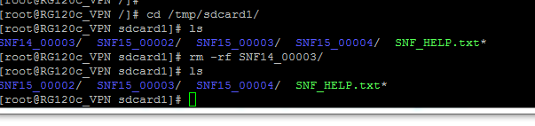
NTP Client
![]()
![]()
The NTP Client Sync function allows the clock to be synchronized with one or more Network Time Protocol (NTP) servers.
| Attributes | Function |
|---|---|
| Object Type | NTP Client |
| Parent(s) | System → Clients |
| Instance | Must be 0. |
| Properties | Values |
|---|---|
| NTP Server #1-6 | Enter one or more IP address of the NTP servers to which to connect. NTP uses algorithms to average the errors between different time servers, and to detect servers which are not reliable. If any server address is set to 0.0.0.0, all subsequent addresses in the list are ignored. A couple of publically available NTP servers you can try are 129.6.15.28 and 129.6.15.29 |
Upon startup, the NTP synchronization is called with a parameter requesting an immediate clock update. This will allow an erroneous clock setting to be more quickly adjusted. Subsequent updates may produce a gradual shift in the clock until the time is precisely correct, based on the normal NTP correction algorithm. The RediGate also schedules the NTP operation to be restarted every 24 hours with an immediate clock update.
Automated Processing
The Automated Processing section of the RediGate configuration is a collection of processes designed primarily to collect data from various sources (RTDB, text files) and format them into a "report" which may be published via MQTT, HTTP, and/or stored to the gateway for later retrieval. Specifically, this allows the automation of data collection from various types of flow computers, such as Omni, Spirit, AutoPilot Pro, Control Microsystems, TotalFlow, or others. The Automated Processing section also includes miscellaneous features such as device time sync, PLC heartbeat, and other forms of script-driven logic which don't require ISaGRAF or POD programming.
See the page Automated Processing for documentation on this feature.
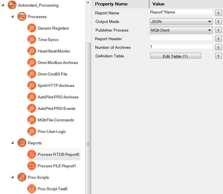
Terminal Client
![]()
![]()
The Terminal Client process connects to a TCP/IP server on a network, and bridges that network connection with a local serial port. This is distinguished from the Terminal Server by the fact that the RediGate initiates the connection to the TCP/IP server, as opposed to an external network client making the network socket connection to the RediGate. The Terminal Client process is similar to the "Reverse Telnet" option available in many routers.
The Terminal Client IP connection may be initiated always at startup of the system or upon receiving any data from a device on the serial port, and it also provides an option as a "modem emulator" whereby the connected serial device can use AT commands to direct which IP address should be connected to.
| Attributes | Function |
|---|---|
| Object Type | TermClient |
| Parent(s) | System → Clients |
| Instance | Use a unique Instance number for each Terminal Client object. |
| Properties | Values |
|---|---|
| Serial Port | From the dropdown list, select the serial port which should be used for connection to this Terminal Client TCP network port. Select the Serial Port from among standard serial ports (COMx) or one instance of a pair of Virtual Port pair (VirCOM xxa or xxb) if connecting this Terminal Client port to another process using Virtual Serial Ports. Make sure the Async port is defined under Networks. |
| Serial Buff Size | Maximum number of bytes which will be put into an IP packet to be sent to the network server. Once receiving this quantity of bytes on the serial port, a TCP packet will be sent immediately. The actual amount of data bytes may be less than the Serial Buff Size, if the Demark Timer (below) times out before the Serial Buffer is full. |
| Demark Timer | Maximum time (in milliseconds) to wait before creating and sending a packet regardless of how many data bytes were received on the serial port. This indicates the assumed "demarcation" time between serial packets. If a serial device is periodically sending messages at a defined interval, setting this Demark Timer too high could cause multiple serial packets to be clumped together in one TCP packet, which may not be desirable. Setting this value too low might cause half of a packet to be sent prematurely if there is a momentary glitch or pause in the serial data stream. |
| Client Reconnect Delay | Enter the time (in seconds) that the Terminal Client will wait after a failure to connect, before attempting to reestablish connection with the Server. This only applies when the connection is unable to be established. If the connection is made and then lost, reconnection will be attempted immediately. |
| Ok AT Commands | Select whether to echo an "OK" to AT commands entered at the Terminal Client serial port. The OK is similar to communicating with a modem over its serial port. |
| DTR Indicates Online | Select whether DTR indicates IP connection state. If set to 'Yes', the serial port's DTR signal will be asserted to a positive voltage when the IP connection is established with a remote server, and will be de-asserted when the IP connection is lost. This emulates the Data Terminal Ready functionality of a dial-up modem, giving a physical indication that an active connection is present. |
| Mode Flag | Select the connection mode of the Terminal Server. Always – Select this option to connect automatically upon system restart or upon the IP socket connection being terminated. If using the "Always" mode of connection, there must be only one child Host Connection object with its Dial String set to an empty field. The Terminal Client will use the IP address of that Host Connection object to automatically connect to the end device. Any Data – Select this option to connect the Terminal Client to the remote server only when data is received on the serial port. If using the "Any Data" mode of connection, there must be only one child Host Connection object with its Dial String set to an empty field. The Terminal Client will use the IP address of that Host Connection object to connect when data is received on the serial port. ATDT – Select this option to connect the Terminal Client only if an "ATDT###" message is received on the serial port, where ### is some alphanumeric string. When using the “ATDT” option, there may be many child Host Connection objects defined under this Terminal Client object. The Host Connection entries should have their Dial String configurations set to unique ATDT### values. The “ATDT” option causes the Terminal Client to act as a modem emulator. The connected serial device acts as if it were connecting using a dial-up modem, where each ATDT dial sequence tells the Terminal Client to connect to a destination IP server, rather than dialing over a PSTN telephone network. DCD – Select this option to connect the Terminal Client only when the DCD signal on the RS-232 serial port is raised to a positive voltage. This option allows a physical voltage input on the serial port to trigger the network socket connection. If using the “DCD” mode of connection, there should be only one child Host Connection object with its Dial String set to an empty field. The Terminal Client will use the IP address of that Host Connection object to connect when the DCD control signal is received. ATDT or DCD – Select this option to connect the Terminal Client in one of two modes described above (the “ATDT” or “DCD” modes). When choosing this option, it is required that one or more Host Connection objects be defined with a configured Dial String, and there should also be only one Host Connection object defined with its Dial String set to an empty field. If an “ATDT###” message is received on the serial port, the matching Host Connection object is used, and the Terminal Client connects to that IP address. If an active DCD signal is present, the Terminal Client connects to the IP address defined in the first Host Connection object containing an empty Dial String field. |
| Time to Live | Number of seconds to close socket after inactivity (0 disables TTL) After 2019, serial buffer is flushed upon TCP connect if TTL > 5. |
Host Connection
![]()
![]()
The Host Connection objects are used in conjunction with the Terminal Client to configure one or more IP addresses to which the Terminal Client will connect, and to allow the Terminal Client to be used as a modem emulator.
| Attributes | Function |
|---|---|
| Object Type | HostCon |
| Parent(s) | System → Clients → TermClient |
| Instance | Use a unique Instance number for each Host Connection object. |
| Properties | Values |
|---|---|
| Dial String | Enter the Dial String, if applicable, in the form “ATDT###”, where ### is some unique alphanumeric string (up to 30 characters). This field may be left blank. If using the Terminal Client in “ATDT” or “ATDT or DCD” connection modes, enter the ATDT#### string that is used to make a connection. Each ATDT string should be configured should be unique among all Host Connection objects under a given Terminal Client. The Dial String has an alternate function when using the Terminal Client to connect to a named server (URL, FQDN). If the Connection Table IP address is set to 0.0.0.0 and Interface set to "DNS", then you can enter a URL in the Dial String field. If using any other connection mode, leave this field blank. In those cases, the IP address(es) defined in the Connection Table become the default IP address used by the Terminal Client to which connection is made. |
| Connect Msg | Enter a string to echo back to the serial device when the Terminal Client is connected to the destination IP address. This is designed to emulate the "Connect" message given by a dial-up modem to a serial terminal program when dialing a PSTN network. |
| Fail Msg | Enter a string to echo back to the host if the connection cannot be established. This is designed to emulate the "Fail" message given by a dial-up modem to a serial terminal program when failing a connection to a PSTN device. |
| Disconnect On | Select from the dropdown menu the conditions under which the Terminal Client should disconnect from the IP network server: Never – Never terminate the Terminal Client from the remote server (remote side can drop the connection at any time). +++ - Disconnect Terminal Client connection from the remote server if the string "+++" is received on the serial port. This must be exactly three pluses in a row. This function emulates the modem attention string often used prior to hanging up a PSTN dial connection. DCD Drop – Disconnect the Terminal Client from the remote server when the DCD input on the RS-232 serial port goes to a low (inactive) state. This can be used in conjunction with the DCD connect option in the Terminal Client, to allow the DCD signal to both connect and disconnect; however, the two configuration options are independent and don't have to be used together. +++ or DCD Drop – Disconnect the Terminal Client from the remote server either upon receiving the string "+++" on the serial port, or when an inactive DCD signal is detected on the serial port. |
| Echo Commands | Select whether to echo all commands. The options are: No – Do not echo characters typed from the serial port. To Async – Echo characters to serial port only. To Async & IP – Echo characters received on the serial port to both the serial port and the remote connected IP server. |
| Fail Over Time | Enter the time (in seconds) to wait after a failed connection attempt until attempting to connect to the next Destination Address, defined in the Connection Table below. |
| Remote IP Port | Port number for the Terminal Client to connect to. If the Host Connect object has a list of Destination IP addresses in the Connection Table, it will always use the same port number with each IP address. |
| Connection Table | Click the Edit Table button to define the IP address(es) and network interface for the Host Connection object. Destination Address – IP address for the Terminal Client to connect to. Configuring a list of more than one IP address provides a fail-over connection in case one connection is unable to connect. Interface – Device interface, which must match the Domain Name in the ACE network configuration objects, such as Ethernet, PPP, etc. (case-sensitive). This tells which interface to use for the connection. To use a named server as the destination (URL or FQDN up to 30 characters) in the Terminal Client instead of an IP address, the following things must be configured:
The DNS feature currently only supports a single URL destination (not multiple failover addresses). Also make sure under Networks to configure the "DNS Servers" object or enable the "Use Peer DNS" option in the CellModem object. |
Global Texts

The Global Text Function allow users to create variables that can be used in the MQTT Clients objects.
| Attributes | Function |
|---|---|
| Object Type | Global Text |
| Parent(s) | System → Clients |
| Instance | Must be 0. |
| Properties | Values |
|---|---|
| Extra Text | Click the Edit Table button to define the variables and corresponding values that will be usable in other areas of the configuration Search Name: Variable name for string replacement. This value will be accessible within an MQTT Client object by typing the name ${Search Name} Replacement Text: Up to 512 chars to replace the original ${Search Name} |
There are a number of pre-defined global text objects that are built-in to the RediGate OS, and thus cannot also be defined in the "Extra Text" field. These pre-defined values are:
| Variable Name | Function |
|---|---|
| ${GATEWAY} | Returns the System → Unit Name of the current configuration |
| ${SERIAL} | Returns the serial number of the RediGate |
| ${UUID} | Returns a universally unique UUID number, commonly used in the MQTT_Extra_Clients3_1 → Client ID property |
Servers
![]()
![]()
The Servers configuration object in ACE is a placeholder under which one or more server processes may be defined. "Servers" are processes that normally wait for some external client to connect to the RediGate. (One exception to this is the UDP Client/Server, which includes both client and server settings in the same object configuration.)
| Attributes | Function |
|---|---|
| Object Type | Servers |
| Parent(s) | System |
| Instance | Must be 0. |
Serial MMI Configuration
![]()
![]()
The Serial MMI object is a system process that allows system diagnostics via a serial user login to the RediGate. The Serial MMI process presents essentially the same user interface as is available via an SSH network connection. See the Diagnostics Manual for details on using the MMI.
A Serial MMI must be configured to use a physical COM port, and therefore the COM port definition must also be included under 'Networks'. The Serial MMI should be defined on the first serial port (COM0) associated with the Linux administrative console. On the RediGate 100 series, COM0 is the USB port.
| Attributes | Function |
|---|---|
| Object Type | SerialMMI |
| Parent(s) | System → Servers |
| Instance | Must be 0. |
| Properties | Values |
|---|---|
| Com Port | Select the COM port on which the Serial MMI will run. NOTE: This should be left at the default setting of COM0. |
| STDERR | Select whether to display standard diagnostic messages on startup. Choose 'Yes' to turn on display of diagnostic messages after startup, even if the user is not logged into the Serial MMI. Choose 'No' to turn off display of startup messages. Diagnostics may still be viewed in the Diagnostic Services menu of the Serial MMI. |
| Inactivity Timeout | The Inactivity Timeout determines the time between the last keypad activity until the user is automatically logged out the diagnostic menu session. Enter the timeout period in minutes. If the Inactivity Timeout is set to 30 minutes or greater, it has a special effect on the user diagnostic option for Custom Reports – the "seconds to delay between refreshes" when viewing a Custom Report can be specified in the range of 1 to 600 seconds. If the Inactivity Timeout is less than 30 minutes, then the Custom Reports refresh rate can only be specified between 5 and 60 seconds. |
| MMI Echo | Select whether to echo typed characters to the terminal. Choose 'Yes' for local echo of typed characters, or 'No' to disable the echo. Default option is 'Yes'. |
Custom Reports
![]()
![]()
The Custom Reports object is an optional child object of the Serial MMI. It allows the system designer to create customized menus to be used in the user interface (via either the Serial MMI or network connection to the MMI). The Custom Reports allow lists of registers from one or more RTDB in the system to be easily displayed for the user, along with descriptive tags, and optionally to allow the user to change values contained in the RTDB registers.
| Attributes | Function |
|---|---|
| Object Type | Custom_Reports |
| Parent(s) | System → Servers → SerialMMI |
| Instance | Must be between 0 and 1000. |
| Properties | Values |
|---|---|
| Report Title | Enter the text to be used as the title of this Custom Report. Title should be text from 1 to 32 characters. |
| Password | Enter the password for this Custom Report. When a user tries to enter a new RTDB value (for Custom Report entries defined as "Write to DBM" or "Write to RTU"), the Password must be entered first. |
| Report Table | Click the Edit Table button to enter the list of RTDB registers to be included in the Custom Report. Report Table fields are: Editable – Select whether to allow a user to change the value in the data address. In all cases, the data in the register may be viewed by the user. Options are:
Label – Enter the label used as an identification for this register when viewed in the Custom Report. Label must be between 1 and 20 characters. If the Label is only a period character, only the register value will be displayed in the Custom Report (no label, and no equal symbol for "Display Only" value). If the previous row uses the "Continue on this row" option for NewLine, this will concatenate the data in this register with the previous one – this may be useful for concatenating multiple consecutive string registers together. Format – Select the default display format for this register in the Custom Report.
Channel – Enter the Channel number where the RTDB is located (either a Master Channel or Internal Channel). RTU – Enter the Field Unit address associated with the RTDB containing the data address (defined under the Channel, above). DataAddr – Enter the RTDB register address of the register to be displayed in the Custom Report. NewLine – Select how to display the next entry in the Custom Report:
Comment - Optional column, allowing a descriptive comment to be entered for each row in the table. The Comment field is unused in the configuration. |
Slave Channels
![]()
![]()
The Slave Channels icon is a placeholder in the ACE configuration, under which individual Slave Channels are defined. Slave Channels allow an external master to poll for data contained in any of the RTDBs defined for this unit.
| Attributes | Function |
|---|---|
| Object Type | SlaveChannels |
| Parent(s) | System → Servers |
| Instance | Must be 0 |
Modbus Serial Slave Channel (SlaveAsync)
![]()
![]()
An Async Slave Channel defines a logical connection from a Modbus master to the RediGate via a serial port. Under the Slave Channel, one or more Modbus slave device addresses may be defined in separate objects, each pointing to an RTDB from which the data is obtained.
| Attributes | Function |
|---|---|
| Object Type | SlaveAsync |
| Parent(s) | System → Servers → SlaveChannels |
| Instance | Must be between 0 and 16. The Async Slave Channel must have at least one Slave Attach object defined. |
| Properties | Values |
|---|---|
| Service | Select the slave type for this Modbus Async Slave Channel. Slave types are: 'Binary Modbus 32 Slave Service' – The Modbus 32 slave service supports the standard Modbus register types as well as 32-bit registers. If any attached Field Unit being polled includes a register of 32-bit data type, the Slave Channel will return one register of 4 bytes. 'Binary Modbus Slave Service (16 Bit Pair)' – The Modbus 16-Bit Pair service supports only standard 16-bit Modbus protocol register types. If any attached Field Unit being polled includes a register of 32-bit data type, the Slave Channel will map each RTDB register into 16-bit register pairs in the Modbus protocol response. |
| Port | Select the communication port to be used for this slave channel. The selected port must be configured under Networks to define the serial communication properties. |
Discussion on Modbus Slave Protocols
To illustrate the difference between Modbus slave types, consider the following two examples.
In both these examples, a Modbus Field Unit has an RTDB containing 20 UINT32 registers (starting at 41,001) and 20 REAL32 registers (starting at 42,001). This Field Unit is attached under a Slave Channel.
In the first example, the Slave channel has the "Binary Modbus 32 Slave Service" protocol selected. The Slave Attach RTU, as seen by the Modbus host, will contain all 32-bit registers (4 bytes per register address). Requesting register 41,020 will return a single 4-byte register from the RTDB register 41,020. This is the same format as indicated by the "32 Bit" data types in the Poll Table of a Modbus Field Unit, when configuring a Modbus master Poll Table.
In the second example, the Slave Channel has the "Binary Modbus 32 Slave Service (16 Bit Pair)" protocol selected. In the Slave attach RTU, the 32-bit registers of the RTDB are represented to the Modbus host as pairs of 16-bit registers (2 bytes per register address). This is the same format as indicated by the "16 Bit Pair" types in the Poll Table of a Modbus Field Unit, when configuring a Modbus master Poll Table.
When a Modbus Host requests registers 42,001-42,002 from the Slave Channel, the RediGate will return the RTDB register 42,001. When the Modbus Host requests registers 42,039-42,040, the RediGate will return the RTDB register 42,020. All 32-bit values must be requested in multiples of 2 without splitting word pairs, or else the RediGate will return an exception response.
Modbus Slave Attach
![]()
![]()
A Slave Attach object defines a logical Modbus slave device, using an attached Field Unit RTDB database as the location containing the data that will be returned upon request by a Modbus master. Only a single RTDB may be included in the Attach List (one RTDB is associated with a given Slave Channel; but the same RTDB could potentially be associated with other Slave Channels, if desired). Multiple Slave Attach objects may be configured under a single Slave Channel, appearing to a host device as a multi-drop network of RTUs or Field Units on a single serial or network port.
| Attributes | Function |
|---|---|
| Object Type | SlaveAsync |
| Parent(s) | System → Servers → SlaveChannels → SlaveAsync |
| Instance | Must be between 0 and 1000. |
| Properties | Values |
|---|---|
| Slave Address | Enter the Modbus slave address that will respond on this slave channel The Slave Address must be a valid Modbus address (1 to 255), and must be unique for all Slave Attach Lists on this Slave Channel. |
| Reserved | Reserved field, currently unused. |
| Source Channel | Master Channel or Internal Channel of the Field Unit and RTDB to be attached to this Slave unit. |
| Source Field Unit | Field Unit address containing the RTDB to be used as data represented in this Slave unit. 32-bit data is only supported in 40,xxx RTDB registers, not 30,xxx registers. In order for the Modbus Slave Attach to work properly, the registers in the attached RTDB must be defined in a specific order. That order is:
NOTE: The RTDB attached to the Modbus slave should include at least one register in each of the four address ranges (1, 10001, 30001, 40001), observing the rules stated in the bullets above. For instance, if the RTDB definition includes 16-bit registers after UINT32 or REAL32 registers, those 16-bit registers will not work properly when attached to the Modbus Slave.
|
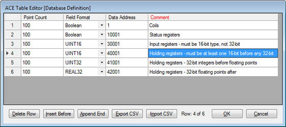
Modbus Network Slave Channel (SlaveNetwork, SlaveModbusTCP)
![]()
![]()
![]()
An SlaveNetwork or SlaveNetworkTCP channel defines a logical connection from a Modbus master to the RediGate via a network TCP/IP port. Under the Slave Channel, one or more Modbus slave device addresses may be defined in separate objects, each pointing to an RTDB from which the data is obtained. Up to six Modbus clients can be connected simultaneously to the same slave channel instance (IP port).
The SlaveNetwork object specifies the use of (serial) Modbus RTU protocol, fully encapsulated within TCP/IP. The SlaveNetworkTCP object specifies Open Modbus/TCP protocol, which is similar to Modbus RTU but with a few differences (6 bytes added to beginning of Modbus packet and no Modbus CRC at the end).
| Attributes | Function |
|---|---|
| Object Type | SlaveNetwork or SlaveModbusTCP |
| Parent(s) | System → Servers → SlaveChannels |
| Instance | Must be between 0 and 16. The Network Slave Channel must have at least one Slave Attach object defined. |
| Properties | Values |
|---|---|
| Service | Select the slave type for this Modbus Async Slave Channel. The "Little Endian" types indicate that the least significant 16 bits occur first in the message. The "Big Endian" type indicate that the most significant 16 bits occur first. Slave types are: 'Modbus 32bit Little Endian Word Slave Service' or 'Modbus-TCP 32 bit Slave Service' – The Modbus 32 slave service supports the standard Modbus register types as well as 32-bit registers. If any attached Field Unit being polled includes a register of 32-bit data type, the Slave Channel will return one register of 4 bytes. 'Modbus 16bit Little Word Endian Slave Service' or 'Modbus-TCP 16 bit pair Slave Service' – The Modbus 16-Bit Pair service supports only standard 16-bit Modbus protocol register types. If any attached Field Unit being polled includes a register of 32-bit data type, the Slave Channel will map each RTDB register into 16-bit register pairs in the Modbus protocol response. See 5-Servers#Async Slave Channel for an example. 'Modbus 32bit Big Endian Word Slave Service' or 'Modbus-TCP 16 bit pair BIG ENDIAN Slave Service' – Same Modbus 32 slave service as above, but using "Big Endian" type. 'Modbus 16bit Big Endian Word Slave Service' or 'Modbus-TCP 32 bit BIG ENDIAN Slave Service' – Same Modbus 32 slave service as above, but using "Big Endian" type. |
| Network Port | Enter the TCP port address that the Modbus host will use to connect to this Slave Channel. If using the SlaveNetwork (encapsulated serial Modbus RTU protocol), there is no standard IP port. If using SlaveNetworkTCP (Open Modbus/TCP), the standard port is 502, although other ports can be used. |
| Network Time to Live | Enter the Time to Live in seconds for the Network Slave Channel. This is the inactivity period for the IP connection. If no Modbus communication is received in this time, the TCP socket will be closed. For an explanation describing the differences between the different protocol Service types (16 or 32 Bit), see 5-Servers#Async Slave Channel. For the Modbus Slave Attach object, see 5-Servers#Modbus Slave Attach. |
Terminal Server
![]()
![]()
The Terminal Server object receives data on a TCP/IP connection and sends the data contained in the IP packet to one or more Async Ports. It also returns data received on the serial port to the connected host.
| Attributes | Function |
|---|---|
| Object Type | TermServ |
| Parent(s) | System → Servers |
| Instance | Must be a unique instance number from other Terminal Servers. The Terminal Server must have a TSPORT slave object defined. |
| Properties | Values |
|---|---|
| Service | Select the "Terminal Server" option. |
| Network Port | Enter the IP Port number of the Terminal Server service. This is the port number to which a TCP/IP client must connect to send serial data. The client may connect to any available IP address configured in this unit's Ethernet or other network object. Up to four simultaneous socket connections to each instance of the Terminal Server are allowed. If used in "Half-Duplex" mode (see the section 5-Servers#Async TS Port), each response will be sent to the host which originated the poll, and any simultaneous request from another host will be delayed until the first poll/response are completed. |
| Network TimeToLive | Enter the time to live for the connection in secs. If there is no network communication for a period of time exceeding the Network TimeToLive, the Terminal Server socket will be closed. If Network TimeToLive is set to 0, the socket will not be closed even if no data is being received. |
Async TS Port
![]()
![]()
The Terminal Server object requires the TS Port child object to be configured. The TS Port object specifies the serial port or ports to which the serial data will be sent after being received from an IP client.
| Attributes | Function |
|---|---|
| Object Type | TSPORT |
| Parent(s) | System → Servers → TermServ |
| Instance | Must be zero. |
| Properties | Values |
|---|---|
| Buffer Size | Maximum number of bytes which will be put into an IP packet response to the network client. If more serial data is received, it will send one TCP packet with the first set of bytes. In Full Duplex mode, additional packets will be sent until all the serial data has been delivered. Actual number of bytes sent may be less than the Buffer Size if the Demark Timer (below) times out before the Serial Buffer is full. |
| Demark | Maximum time (in milliseconds) to wait before creating and sending a response packet. If at least one byte is received on the serial port, then a gap between bytes exceeding the Demark time is used to determine when the end of the data has been received. |
| Response TimeOut | Enter the response timeout in seconds. This is the maximum time allowed for a response from the serial device, such as a Modbus RTU. It is also used as a switch between three modes of operation: "Send and Forget" (Timeout = 0) – This allows the network host to send data to a serial device, but not wait to receive any serial data. |
| Port Table | Click the Edit Table button to select one or more serial ports to use for Terminal Server communication. ComPort – Append one or more rows with unique serial ports listed. If more than one port is selected, data received on the TCP port is sent to all of the configured serial ports. In Half Duplex mode, only one response on one port is received and returned to the client. All later responses on any ports will be ignored. In Full Duplex mode, all serial ports are monitored constantly for incoming data, which is returned to the network client. |
TcpModbusTranslate
![]()
![]()
The TCPModbusTranslate is an optional child object of the Terminal Server, which performs an on-the-fly translation from OpenModbus/TCP protocol to standard serial Modbus. The OpenModbus/TCP is a proprietary version of Modbus that uses a similar format to serial Modbus, but with different header information. This allows an OpenModbus/TCP host to communicate with a standard serial Modbus device.
Do not use this ACE object when the transmitted data is not Modbus, or when the TCP communication contains serial Modbus messages encapsulated within TCP packets, because there is no translation needed in those cases.
| Attributes | Function |
|---|---|
| Object Type | TcpModbusTranslate |
| Parent(s) | System → Servers → TermServ |
| Instance | Must be zero. |
| Properties | Values |
|---|---|
| Conversion | Select the Modbus mode to convert on the serial side: RTU (binary) Modbus ASCII Modbus |
| Defragmentation Timer | Enter the number of milliseconds to wait for the full packet of Modbus data to arrive from the Open Modbus/TCP host. This is used in case there is data packet fragmentation on the TCP/IP side. Enter 0 to disable the option of reassembling fragmented packets. |
HCP RBE Server
![]()
![]()
The HCP RBE server allows an HCP to connect to the RediGate on a TCP/IP socket for receiving RBE (Report By Exception) data. RBE messages are generated automatically by any Field Unit that is configured to produce RBEs, whenever the data in a register changes by more than the configured deadband value.
If using with HCP2 rather than HCP, set the port numbers for RBE and PR objects to be the same. In this case, the HCP makes a single socket connection to the listening server on the RediGate and uses this single connection for both RBE and PR messages, thus reducing the number of required open sockets on the HCP machine.
Note that the RBE data is only sent for a Field Unit that is marked as alive by the Master Channel. A unit will be marked as failed if any of its polls (with period less than the Scan Effective Limit) failed on the last attempt.
| Attributes | Function |
|---|---|
| Object Type | HCPRBEServer |
| Parent(s) | System → Servers |
| Instance | Must be between 0 and 1. This allows a second listening socket for communication with a backup HCP. |
| Properties | Values |
|---|---|
| Service | Select the service type "Network RBE Service to HCP" |
| Network Port | Enter the port number to listen for HCP connections. When using multiple connections to redundant HCPs, all RBE and PR objects must use unique port numbers. |
| Network Time To Live | Enter the inactivity period (in seconds) for the connection before disconnecting the TCP socket. |
| RBE Pacing | Milliseconds to wait between sending each RBE packet. The RBE task periodically checks the RBE flags set for each point in the RTDB to see if data has changed. If one or more points has changed more than the deadband, all changed points are sent to the HCP in an unsolicited packet. This parameter defines how often to perform this check for changed data. |
HCP PR Server
![]()
![]()
The HCP PR server allows an HCP to connect to the RediGate on a TCP/IP socket for receiving PR (poll/response) data. PR messages are sent from a SCADA master to the HCP, passed to the RediGate on its PR port, and then passed to the attached Field Unit. Response data is returned to the master via the HCP.
| Attributes | Function |
|---|---|
| Object Type | HCPPRServer |
| Parent(s) | System → Servers |
| Instance | Must be between 0 and 1. This allows a second listening socket for connection to a backup HCP. |
| Properties | Values |
|---|---|
| Service | Select the service type "Network Poll/Response Service to HCP". |
| Network Port | Enter the port number that the HCP will use to connect. When using multiple connections to redundant HCPs, all RBE and PR objects must use unique port numbers. |
| HealthCheck Time | Number of seconds to wait for a Health Check message from the HCP. HealthCheck messages are sent from the HCP on the PR port and returned to the HCP over the RBE port. If the HealthCheck message is not received in this amount of time, the RediGate will shut down both its PR and RBE sockets for that HCP and wait for another connection to be made by the HCP. |
| Response Timeout | Enter the number of seconds that the HCP will wait for a HealthCheck response. The Response Timeout is not used by the RediGate. This parameter is placed in the RediGate configuration files but is only used by the HCP. If the HCP doesn't receive a response within the configured time, the HCP will shut down the PR and RBE sockets and reconnect. |
UDP Server/Client
UDP Port (McPORT)
![]()
![]()
The UDP Server/Client object requires the UDP Port child object to be configured. The UDP Port object specifies the serial port or ports which will be used to exchange data with the UDP client or server IP port.
| Attributes | Function |
|---|---|
| Object Type | McPORT |
| Parent(s) | System → Servers → UdpServ |
| Instance | Must be zero. |
| Properties | Values |
|---|---|
| Buffer Size | When used in UDP Client mode, this defines the maximum number of bytes which will be put into an IP packet response to the network client. If more serial data is received, it will send one UDP packet with the first set of bytes. Additional packets will be sent until all the serial data has been delivered. Actual number of bytes sent may be less than the Buffer Size if the Demark Timer (below) times out before the Serial Buffer is full. When used in UDP Server mode, this setting will empty out the IP buffer to the serial port in batches of bytes up to the Buffer Size. |
| Demark | When used in UDP Client mode, this defines the maximum time (in milliseconds) to wait before creating and sending a response packet after receiving some data on the serial port. If at least one byte is received on the serial port, then a gap between bytes exceeding the Demark time is used to determine when the end of the data has been received for a given UDP packet. When used in UDP Server mode, this parameter is unused. |
| Mask Packet Size | The UDP Server has an optional feature that allows packets of a specific number of bytes to be blocked, so that they are not passed from the UDP Server port to the serial port(s). In UDP Client mode, this feature is unused. Enter 0 to disable this feature, or enter the number of bytes to block packets of this size. Number of bytes includes only data bytes in the data message, not the total size with UDP/IP header bytes. |
| Port Table | Click the Edit Table button to select one or more serial ports to use for UDP communication. ComPort – Append one or more rows with unique serial ports listed. If more than one port is selected, data received on the UDP port is sent to all of the configured serial ports (in UDP Server mode), or all data received on the serial ports is put into a UDP packet (in UDP Client mode). |
UDP Handler
The UDP Handler is a process that listens for an incoming UDP message (which can include multicast or broadcast messages on a network) and rebroadcasts the message to one or more specific or broadcast IP addresses, either on the same or a different network interface.
| Attributes | Function |
|---|---|
| Object Type | UdpHandler |
| Parent(s) | System → Servers |
| Instance | Must be a unique instance number from other UDP Handler objects |
| Properties | Values |
|---|---|
| Interface | This field is REQUIRED to match the Linux interface name on which to listen for an incoming UDP packet (e.g., use "eth0" for Ethernet 0 port, "lo" for local interface, etc. |
| IP Address | Enter the IP address on which to listen for the incoming UDP message. This may be a specific IP (e.g. 10.63.37.21 or 127.0.0.1), broadcast (e.g. 10.63.255.255), or multicast address (e.g. 224.1.1.1). |
| UDP Port | Enter the UDP port on which to listen as a UDP server for the incoming message. |
Allow Forwarding Back | Select whethe to allow the forwarded message to be returned on the same network interface as the source. |
| Output Table | Click the Edit Table button to select one or more destinations to forward the incoming UDP message. Interface –This field is REQUIRED to match the Linux interface name on which to send an outbound UDP packet (e.g., use "eth0" for Ethernet 0 port, "lo" for local interface, etc. Destination IP Address –Enter the IP address to use for forwarding the UDP data. This may be a specific IP, broadcast, or multicast address. UDP Port – Enter the UDP port to use for forwarding the UDP data. Multicast TTL – Enter a number between 0 and 255 for the Time to Live value of output IP packets. The TTL is used to control how far a datagram can traverse the network, since the value in a packet is decremented each time it passes through a router. The TTL also has a special use in multicast packets to restrict the region over which the packets can be forwarded. Packet Size Filter – Select a filter type for the size of UDP data packet to forward. This may be used, for instance, if several multicast packets exist on a network but your application requires forwarding a particular packet of a known size. This options is used with the Mask Packet Size property.
Mask Packet Size – Packet size used with the Packet Size Filter field. General Info – Optional text string (up to 32 characters), which can be used as a comment within the configuration to provide a description or purpose of each row of data in the Output Table (has no operational purpose for the UDP Handler). |
SmartMux
![]()
![]()
The SmartMux object is a multiplexer for serial protocol communication. It receives data on one of several host serial ports, and passes the data to a single shared serial port. The response packets on the shared port are intelligently routed back to one or more host ports. Depending on the protocol, the SmartMux can route packets in poll-response mode or unsolicited data.
Following are several types of examples how the SmartMux might be used:
- Two or more Modbus host ports need to communicate to one or more Modbus devices on a single serial port. The Host Ports will be configured for Modbus, and the Shared Port will be connected to the interface where the devices exist. The SmartMux will allow the Modbus masters to cleanly poll the device(s), even if they send polls simultaneously, but waiting for one poll-response to complete before allowing the next poll through.
- A SPY port can be configured that will monitor all polls and responses on all the other Host Ports and Shared Port. This might be used for troubleshooting.
- A Modbus host and a different protocol host (of a type not supported by the SmartMux) are polling devices attached to a shared port. The Protocol for the Modbus host port will be set to Modbus, and the other Host Port will be set to Generic protocol to match based on a criteria of a certain range of values in a byte position of the response that is unique to that protocol. This will allow responses from the other protocol to be routed back to its master.
For instance, the Shared Port can be connected with a host computer that sends out requests to devices of different communication protocols. The SmartMux looks at each data packet received on the Shared Port to determine the protocol, and routes the packet to the appropriate mux port. The device connected on the mux port may send a response, which is routed back to the host device on the Shared Port.
| Attributes | Function |
|---|---|
| Object Type | SmartMux |
| Parent(s) | System → Servers |
| Instance | Must be unique from other SmartMux objects. |
| Properties | Values |
|---|---|
| Shared Port | Select the serial port that will be shared by one or more Host Ports. |
| Buffer Size | Enter the maximum data packet size (in bytes) accepted on the shared serial port (up to 4095). |
| Demarc Time | Enter the demarcation time (in milliseconds). The demarcation time specifies the interval between bytes that is used to determine the end of a complete data packet received on the shared serial port. |
| Transmit Delay | Enter the time (in milliseconds) between data packets transmitted on the Shared Port. This can be used if more than one host is transmitting to the shared port, and you want to ensure a minimum delay between one response from the shared port and the next transmit to it. |
| Protocol Definitions | Click the Edit Table button to enter details of each of the multiplexed host ports and protocols supported on the SmartMux. As messages are received on the Shared Port, they are evaluated in the sequential order of the Protocol Definitions. Once a match is obtained, no further Protocol Definitions are checked for a match. Example: The first row is "Modbus" protocol, and the second row is defined as a "Generic Protocol" to match specific bytes in the message. A Modbus poll comes into the Modbus host port, is forwarded to the Shared Port, and a response is received. Because the response message will match the Modbus protocol in the first Protocol Definition, the packet will be returned to the Modbus host port, and the RediGate will not check the message for the byte position values of the Generic protocol definition. If the order of rows is turned around, the Generic Protocol matching will be checked first. Host Port – Select the mux port on which to send the protocol data that matches the criteria in this Protocol Definition row. Mux ports can be real serial ports, or Virtual Ports that connect internally to other serial processes. Enter a valid and unique unit address between 1 and 255. The Unit Address is used in some host systems: - Identifies this unit in an Elecsys HCP (must be unique) - Identifies this unit in an Elecsys OPC Server (must be unique) - May be part of topic string to MQTT broker/OPC Server, if configured in the MQ RBE object (must be unique if using Topic option with "UnitAddress") Note that the "Unit Address" property is different from any individual Field Unit being polled and reported to the host. The Unit Address refers to the RediGate itself, and must be explicitly configured to be unique across all devices reporting to the HCP or MQTT/OPC Server. |
| Properties | Values |
|---|---|
| Interval Delay | Scans between RBE data refreshes. If RBE Flag parater is set to "All DBM Flags", there is one interval delay per flag (interval x 4 for each flag). |
| RBE Flag | Which RBE Flags in DBM to set |
| Device List | Selecy which field units to enable RBE flags. If empty, update ALL RTDB's |