...
| Properties | Values |
|---|---|
| Com Port | Select the COM port on which the Serial MMI will run. NOTE: This should be left at the default setting of COM0. |
| STDERR | Select whether to display standard diagnostic messages on startup. Choose 'Yes' to turn on display of diagnostic messages after startup, even if the user is not logged into the Serial MMI. Choose 'No' to turn off display of startup messages. Diagnostics may still be viewed in the Diagnostic Services menu of the Serial MMI. |
| Inactivity Timeout | The Inactivity Timeout determines the time between the last keypad activity until the user is automatically logged out the diagnostic menu session. Enter the timeout period in minutes. If the Inactivity Timeout is set to 30 minutes or greater, it has a special effect on the user diagnostic option for Custom Reports – the "seconds to delay between refreshes" when viewing a Custom Report can be specified in the range of 1 to 600 seconds. If the Inactivity Timeout is less than 30 minutes, then the Custom Reports refresh rate can only be specified between 5 and 60 seconds. |
| MMI Echo | Select whether to echo typed characters to the terminal. Choose 'Yes' for local echo of typed characters, or 'No' to disable the echo. Default option is 'Yes'. |
...
| Properties | Values |
|---|---|
| Slave Address | Enter the Modbus slave address that will respond on this slave channel The Slave Address must be a valid Modbus address (1 to 255), and must be unique for all Slave Attach Lists on this Slave Channel. |
| Reserved | Reserved field, currently unused. |
| Source Channel | Master Channel or Internal Channel of the Field Unit and RTDB to be attached to this Slave unit. |
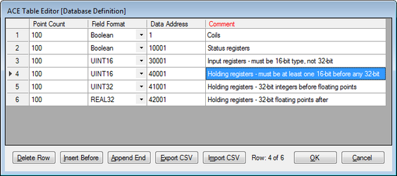
| Source Field Unit | Field Unit address containing the RTDB to be used as data represented in this Slave unit. 32-bit data is only supported in 40,xxx RTDB registers, not 30,xxx registers. In order for the Modbus Slave Attach to work properly, the registers in the attached RTDB must be defined in a specific order. That order is:
NOTE: The RTDB attached to the Modbus slave should include at least one register in each of the four address ranges (1, 10001, 30001, 40001), observing the rules stated in the bullets above. For instance, if the RTDB definition includes 16-bit registers after UINT32 or REAL32 registers, those 16-bit registers will not work properly when attached to the Modbus Slave.
|
...
Modbus Network Slave Channel (SlaveNetwork, SlaveModbusTCP)
...
| Properties | Values |
|---|---|
| Service | Select the slave type for this Modbus Async Slave Channel. The "Little Endian" types indicate that the least significant 16 bits occur first in the message. The "Big Endian" type indicate that the most significant 16 bits occur first. Slave types are: 'Modbus 32bit Little Endian Word Slave Service' or 'Modbus-TCP 32 bit Slave Service' – The Modbus 32 slave service supports the standard Modbus register types as well as 32-bit registers. If any attached Field Unit being polled includes a register of 32-bit data type, the Slave Channel will return one register of 4 bytes. 'Modbus 16bit Little Word Endian Slave Service' or 'Modbus-TCP 16 bit pair Slave Service' – The Modbus 16-Bit Pair service supports only standard 16-bit Modbus protocol register types. If any attached Field Unit being polled includes a register of 32-bit data type, the Slave Channel will map each RTDB register into 16-bit register pairs in the Modbus protocol response. See Async Slave Channel39583745 for an example. 'Modbus 32bit Big Endian Word Slave Service' or 'Modbus-TCP 16 bit pair BIG ENDIAN Slave Service' – Same Modbus 32 slave service as above, but using "Big Endian" type. 'Modbus 16bit Big Endian Word Slave Service' or 'Modbus-TCP 32 bit BIG ENDIAN Slave Service' – Same Modbus 32 slave service as above, but using "Big Endian" type. |
| Network Port | Enter the TCP port address that the Modbus host will use to connect to this Slave Channel. If using the SlaveNetwork (encapsulated serial Modbus RTU protocol), there is no standard IP port. If using SlaveNetworkTCP (Open Modbus/TCP), the standard port is 502, although other ports can be used. |
| Network Time to Live | Enter the Time to Live in seconds for the Network Slave Channel. This is the inactivity period for the IP connection. If no Modbus communication is received in this time, the TCP socket will be closed. For an explanation describing the differences between the different protocol Service types (16 or 32 Bit), see Async Slave Channel39583745. For the Modbus Slave Attach object, see Modbus Slave Attach39583745. |
Terminal Server
![]()
![]()
The Terminal Server object receives data on a TCP/IP connection and sends the data contained in the IP packet to one or more Async Ports. It also returns data received on the serial port to the connected host.
...
| Properties | Values |
|---|---|
| Service | Select the "Terminal Server" option. |
| Network Port | Enter the IP Port number of the Terminal Server service. This is the port number to which a TCP/IP client must connect to send serial data. The client may connect to any available IP address configured in this unit's Ethernet or other network object. Up to four simultaneous socket connections to each instance of the Terminal Server are allowed. If used in "Half-Duplex" mode (see the section Async TS Port39583745), each response will be sent to the host which originated the poll, and any simultaneous request from another host will be delayed until the first poll/response are completed. |
| Network TimeToLive | Enter the time to live for the connection in secs. If there is no network communication for a period of time exceeding the Network TimeToLive, the Terminal Server socket will be closed. If Network TimeToLive is set to 0, the socket will not be closed even if no data is being received. |
...
| Properties | Values |
|---|---|
| Buffer Size | Maximum number of bytes which will be put into an IP packet response to the network client. If more serial data is received, it will send one TCP packet with the first set of bytes. In Full Duplex mode, additional packets will be sent until all the serial data has been delivered. Actual number of bytes sent may be less than the Buffer Size if the Demark Timer (below) times out before the Serial Buffer is full. |
| Demark | Maximum time (in milliseconds) to wait before creating and sending a response packet. If at least one byte is received on the serial port, then a gap between bytes exceeding the Demark time is used to determine when the end of the data has been received. |
| Response TimeOut | Enter the response timeout in seconds. This is the maximum time allowed for a response from the serial device, such as a Modbus RTU. It is also used as a switch between three modes of operation: "Send and Forget" (Timeout = 0) – This allows the network host to send data to a serial device, but not wait to receive any serial data. |
| Port Table | Click the Edit Table button to select one or more serial ports to use for Terminal Server communication. ComPort – Append one or more rows with unique serial ports listed. If more than one port is selected, data received on the TCP port is sent to all of the configured serial ports. In Half Duplex mode, only one response on one port is received and returned to the client. All later responses on any ports will be ignored. In Full Duplex mode, all serial ports are monitored constantly for incoming data, which is returned to the network client. |
...
TcpModbusTranslate
![]()
![]()
The TCPModbusTranslate is an optional child object of the Terminal Server, which performs an on-the-fly translation from OpenModbus/TCP protocol to standard serial Modbus. The OpenModbus/TCP is a proprietary version of Modbus that uses a similar format to serial Modbus, but with different header information. This allows an OpenModbus/TCP host to communicate with a standard serial Modbus device.
...
| Properties | Values |
|---|---|
| Shared Port | Select the serial port that will be shared by one or more Host Ports. |
| Buffer Size | Enter the maximum data packet size (in bytes) accepted on the shared serial port (up to 4095). |
| Demarc Time | Enter the demarcation time (in milliseconds). The demarcation time specifies the interval between bytes that is used to determine the end of a complete data packet received on the shared serial port. |
| Transmit Delay | Enter the time (in milliseconds) between data packets transmitted on the Shared Port. This can be used if more than one host is transmitting to the shared port, and you want to ensure a minimum delay between one response from the shared port and the next transmit to it. |
| Protocol Definitions | Click the Edit Table button to enter details of each of the multiplexed host ports and protocols supported on the SmartMux. As messages are received on the Shared Port, they are evaluated in the sequential order of the Protocol Definitions. Once a match is obtained, no further Protocol Definitions are checked for a match. Example: The first row is "Modbus" protocol, and the second row is defined as a "Generic Protocol" to match specific bytes in the message. A Modbus poll comes into the Modbus host port, is forwarded to the Shared Port, and a response is received. Because the response message will match the Modbus protocol in the first Protocol Definition, the packet will be returned to the Modbus host port, and the RediGate will not check the message for the byte position values of the Generic protocol definition. If the order of rows is turned around, the Generic Protocol matching will be checked first. Host Port – Select the mux port on which to send the protocol data that matches the criteria in this Protocol Definition row. Mux ports can be real serial ports, or Virtual Ports that connect internally to other serial processes. Enter a valid and unique unit address between 1 and 255. The Unit Address is used in some host systems: - Identifies this unit in an Elecsys HCP (must be unique) - Identifies this unit in an Elecsys OPC Server (must be unique) - May be part of topic string to MQTT broker/OPC Server, if configured in the MQ RBE object (must be unique if using Topic option with "UnitAddress") Note that the "Unit Address" property is different from any individual Field Unit being polled and reported to the host. The Unit Address refers to the RediGate itself, and must be explicitly configured to be unique across all devices reporting to the HCP or MQTT/OPC Server. |
...
| Properties | Values |
|---|---|
| Interval Delay | Scans between RBE data refreshes. If RBE Flag parater is set to "All DBM Flags", there is one interval delay per flag (interval x 4 for each flag). |
| RBE Flag | Which RBE Flags in DBM to set |
| Device List | Selecy which field units to enable RBE flags. If empty, update ALL RTDB's |
...