5-Servers
- Jon Tandy
- Former user (Deleted)
Servers
![]()
![]()
The Servers configuration object in ACE is a placeholder under which one or more server processes may be defined. "Servers" are processes that normally wait for some external client to connect to the RediGate. (One exception to this is the UDP Client/Server, which includes both client and server settings in the same object configuration.)
| Attributes | Function |
|---|---|
| Object Type | Servers |
| Parent(s) | System |
| Instance | Must be 0. |
Serial MMI Configuration
![]()
![]()
The Serial MMI object is a system process that allows system diagnostics via a serial user login to the RediGate. The Serial MMI process presents essentially the same user interface as is available via an SSH network connection. See the Diagnostics Manual for details on using the MMI.
A Serial MMI must be configured to use a physical COM port, and therefore the COM port definition must also be included under 'Networks'. The Serial MMI should be defined on the first serial port (COM0) associated with the Linux administrative console. On the RediGate 100 series, COM0 is the USB port.
| Attributes | Function |
|---|---|
| Object Type | SerialMMI |
| Parent(s) | System → Servers |
| Instance | Must be 0. |
| Properties | Values |
|---|---|
| Com Port | Select the COM port on which the Serial MMI will run. NOTE: This should be left at the default setting of COM0. |
| STDERR | Select whether to display standard diagnostic messages on startup. Choose 'Yes' to turn on display of diagnostic messages after startup, even if the user is not logged into the Serial MMI. Choose 'No' to turn off display of startup messages. Diagnostics may still be viewed in the Diagnostic Services menu of the Serial MMI. |
| Inactivity Timeout | The Inactivity Timeout determines the time between the last keypad activity until the user is automatically logged out the diagnostic menu session. Enter the timeout period in minutes. If the Inactivity Timeout is set to 30 minutes or greater, it has a special effect on the user diagnostic option for Custom Reports – the "seconds to delay between refreshes" when viewing a Custom Report can be specified in the range of 1 to 600 seconds. If the Inactivity Timeout is less than 30 minutes, then the Custom Reports refresh rate can only be specified between 5 and 60 seconds. |
| MMI Echo | Select whether to echo typed characters to the terminal. Choose 'Yes' for local echo of typed characters, or 'No' to disable the echo. Default option is 'Yes'. |
Custom Reports
![]()
![]()
The Custom Reports object is an optional child object of the Serial MMI. It allows the system designer to create customized menus to be used in the user interface (via either the Serial MMI or network connection to the MMI). The Custom Reports allow lists of registers from one or more RTDB in the system to be easily displayed for the user, along with descriptive tags, and optionally to allow the user to change values contained in the RTDB registers.
| Attributes | Function |
|---|---|
| Object Type | Custom_Reports |
| Parent(s) | System → Servers → SerialMMI |
| Instance | Must be between 0 and 1000. |
| Properties | Values |
|---|---|
| Report Title | Enter the text to be used as the title of this Custom Report. Title should be text from 1 to 32 characters. |
| Password | Enter the password for this Custom Report. When a user tries to enter a new RTDB value (for Custom Report entries defined as "Write to DBM" or "Write to RTU"), the Password must be entered first. |
| Report Table | Click the Edit Table button to enter the list of RTDB registers to be included in the Custom Report. Report Table fields are: Editable – Select whether to allow a user to change the value in the data address. In all cases, the data in the register may be viewed by the user. Options are:
Label – Enter the label used as an identification for this register when viewed in the Custom Report. Label must be between 1 and 20 characters. If the Label is only a period character, only the register value will be displayed in the Custom Report (no label, and no equal symbol for "Display Only" value). If the previous row uses the "Continue on this row" option for NewLine, this will concatenate the data in this register with the previous one – this may be useful for concatenating multiple consecutive string registers together. Format – Select the default display format for this register in the Custom Report.
Channel – Enter the Channel number where the RTDB is located (either a Master Channel or Internal Channel). RTU – Enter the Field Unit address associated with the RTDB containing the data address (defined under the Channel, above). DataAddr – Enter the RTDB register address of the register to be displayed in the Custom Report. NewLine – Select how to display the next entry in the Custom Report:
Comment - Optional column, allowing a descriptive comment to be entered for each row in the table. The Comment field is unused in the configuration. |
Slave Channels
![]()
![]()
The Slave Channels icon is a placeholder in the ACE configuration, under which individual Slave Channels are defined. Slave Channels allow an external master to poll for data contained in any of the RTDBs defined for this unit.
| Attributes | Function |
|---|---|
| Object Type | SlaveChannels |
| Parent(s) | System → Servers |
| Instance | Must be 0 |
Modbus Serial Slave Channel (SlaveAsync)
![]()
![]()
An Async Slave Channel defines a logical connection from a Modbus master to the RediGate via a serial port. Under the Slave Channel, one or more Modbus slave device addresses may be defined in separate objects, each pointing to an RTDB from which the data is obtained.
| Attributes | Function |
|---|---|
| Object Type | SlaveAsync |
| Parent(s) | System → Servers → SlaveChannels |
| Instance | Must be between 0 and 16. The Async Slave Channel must have at least one Slave Attach object defined. |
| Properties | Values |
|---|---|
| Service | Select the slave type for this Modbus Async Slave Channel. Slave types are: 'Binary Modbus 32 Slave Service' – The Modbus 32 slave service supports the standard Modbus register types as well as 32-bit registers. If any attached Field Unit being polled includes a register of 32-bit data type, the Slave Channel will return one register of 4 bytes. 'Binary Modbus Slave Service (16 Bit Pair)' – The Modbus 16-Bit Pair service supports only standard 16-bit Modbus protocol register types. If any attached Field Unit being polled includes a register of 32-bit data type, the Slave Channel will map each RTDB register into 16-bit register pairs in the Modbus protocol response. |
| Port | Select the communication port to be used for this slave channel. The selected port must be configured under Networks to define the serial communication properties. |
Discussion on Modbus Slave Protocols
To illustrate the difference between Modbus slave types, consider the following two examples.
In both these examples, a Modbus Field Unit has an RTDB containing 20 UINT32 registers (starting at 41,001) and 20 REAL32 registers (starting at 42,001). This Field Unit is attached under a Slave Channel.
In the first example, the Slave channel has the "Binary Modbus 32 Slave Service" protocol selected. The Slave Attach RTU, as seen by the Modbus host, will contain all 32-bit registers (4 bytes per register address). Requesting register 41,020 will return a single 4-byte register from the RTDB register 41,020. This is the same format as indicated by the "32 Bit" data types in the Poll Table of a Modbus Field Unit, when configuring a Modbus master Poll Table.
In the second example, the Slave Channel has the "Binary Modbus 32 Slave Service (16 Bit Pair)" protocol selected. In the Slave attach RTU, the 32-bit registers of the RTDB are represented to the Modbus host as pairs of 16-bit registers (2 bytes per register address). This is the same format as indicated by the "16 Bit Pair" types in the Poll Table of a Modbus Field Unit, when configuring a Modbus master Poll Table.
When a Modbus Host requests registers 42,001-42,002 from the Slave Channel, the RediGate will return the RTDB register 42,001. When the Modbus Host requests registers 42,039-42,040, the RediGate will return the RTDB register 42,020. All 32-bit values must be requested in multiples of 2 without splitting word pairs, or else the RediGate will return an exception response.
Modbus Slave Attach
![]()
![]()
A Slave Attach object defines a logical Modbus slave device, using an attached Field Unit RTDB database as the location containing the data that will be returned upon request by a Modbus master. Only a single RTDB may be included in the Attach List (one RTDB is associated with a given Slave Channel; but the same RTDB could potentially be associated with other Slave Channels, if desired). Multiple Slave Attach objects may be configured under a single Slave Channel, appearing to a host device as a multi-drop network of RTUs or Field Units on a single serial or network port.
| Attributes | Function |
|---|---|
| Object Type | SlaveAsync |
| Parent(s) | System → Servers → SlaveChannels → SlaveAsync |
| Instance | Must be between 0 and 1000. |
| Properties | Values |
|---|---|
| Slave Address | Enter the Modbus slave address that will respond on this slave channel The Slave Address must be a valid Modbus address (1 to 255), and must be unique for all Slave Attach Lists on this Slave Channel. |
| Reserved | Reserved field, currently unused. |
| Source Channel | Master Channel or Internal Channel of the Field Unit and RTDB to be attached to this Slave unit. |
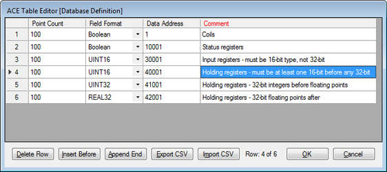
| Source Field Unit | Field Unit address containing the RTDB to be used as data represented in this Slave unit. 32-bit data is only supported in 40,xxx RTDB registers, not 30,xxx registers. In order for the Modbus Slave Attach to work properly, the registers in the attached RTDB must be defined in a specific order. That order is:
NOTE: The RTDB attached to the Modbus slave should include at least one register in each of the four address ranges (1, 10001, 30001, 40001), observing the rules stated in the bullets above. For instance, if the RTDB definition includes 16-bit registers after UINT32 or REAL32 registers, those 16-bit registers will not work properly when attached to the Modbus Slave.
|
Modbus Network Slave Channel (SlaveNetwork, SlaveModbusTCP)
![]()
![]()
![]()
An SlaveNetwork or SlaveNetworkTCP channel defines a logical connection from a Modbus master to the RediGate via a network TCP/IP port. Under the Slave Channel, one or more Modbus slave device addresses may be defined in separate objects, each pointing to an RTDB from which the data is obtained. Up to six Modbus clients can be connected simultaneously to the same slave channel instance (IP port).
The SlaveNetwork object specifies the use of (serial) Modbus RTU protocol, fully encapsulated within TCP/IP. The SlaveNetworkTCP object specifies Open Modbus/TCP protocol, which is similar to Modbus RTU but with a few differences (6 bytes added to beginning of Modbus packet and no Modbus CRC at the end).
| Attributes | Function |
|---|---|
| Object Type | SlaveNetwork or SlaveModbusTCP |
| Parent(s) | System → Servers → SlaveChannels |
| Instance | Must be between 0 and 16. The Network Slave Channel must have at least one Slave Attach object defined. |
| Properties | Values |
|---|---|
| Service | Select the slave type for this Modbus Async Slave Channel. The "Little Endian" types indicate that the least significant 16 bits occur first in the message. The "Big Endian" type indicate that the most significant 16 bits occur first. Slave types are: 'Modbus 32bit Little Endian Word Slave Service' or 'Modbus-TCP 32 bit Slave Service' – The Modbus 32 slave service supports the standard Modbus register types as well as 32-bit registers. If any attached Field Unit being polled includes a register of 32-bit data type, the Slave Channel will return one register of 4 bytes. 'Modbus 16bit Little Word Endian Slave Service' or 'Modbus-TCP 16 bit pair Slave Service' – The Modbus 16-Bit Pair service supports only standard 16-bit Modbus protocol register types. If any attached Field Unit being polled includes a register of 32-bit data type, the Slave Channel will map each RTDB register into 16-bit register pairs in the Modbus protocol response. See 5-Servers#Async Slave Channel for an example. 'Modbus 32bit Big Endian Word Slave Service' or 'Modbus-TCP 16 bit pair BIG ENDIAN Slave Service' – Same Modbus 32 slave service as above, but using "Big Endian" type. 'Modbus 16bit Big Endian Word Slave Service' or 'Modbus-TCP 32 bit BIG ENDIAN Slave Service' – Same Modbus 32 slave service as above, but using "Big Endian" type. |
| Network Port | Enter the TCP port address that the Modbus host will use to connect to this Slave Channel. If using the SlaveNetwork (encapsulated serial Modbus RTU protocol), there is no standard IP port. If using SlaveNetworkTCP (Open Modbus/TCP), the standard port is 502, although other ports can be used. |
| Network Time to Live | Enter the Time to Live in seconds for the Network Slave Channel. This is the inactivity period for the IP connection. If no Modbus communication is received in this time, the TCP socket will be closed. For an explanation describing the differences between the different protocol Service types (16 or 32 Bit), see 5-Servers#Async Slave Channel. For the Modbus Slave Attach object, see 5-Servers#Modbus Slave Attach. |
Terminal Server
![]()
![]()
The Terminal Server object receives data on a TCP/IP connection and sends the data contained in the IP packet to one or more Async Ports. It also returns data received on the serial port to the connected host.
| Attributes | Function |
|---|---|
| Object Type | TermServ |
| Parent(s) | System → Servers |
| Instance | Must be a unique instance number from other Terminal Servers. The Terminal Server must have a TSPORT slave object defined. |
| Properties | Values |
|---|---|
| Service | Select the "Terminal Server" option. |
| Network Port | Enter the IP Port number of the Terminal Server service. This is the port number to which a TCP/IP client must connect to send serial data. The client may connect to any available IP address configured in this unit's Ethernet or other network object. Up to four simultaneous socket connections to each instance of the Terminal Server are allowed. If used in "Half-Duplex" mode (see the section 5-Servers#Async TS Port), each response will be sent to the host which originated the poll, and any simultaneous request from another host will be delayed until the first poll/response are completed. |
| Network TimeToLive | Enter the time to live for the connection in secs. If there is no network communication for a period of time exceeding the Network TimeToLive, the Terminal Server socket will be closed. If Network TimeToLive is set to 0, the socket will not be closed even if no data is being received. |
Async TS Port
![]()
![]()
The Terminal Server object requires the TS Port child object to be configured. The TS Port object specifies the serial port or ports to which the serial data will be sent after being received from an IP client.
| Attributes | Function |
|---|---|
| Object Type | TSPORT |
| Parent(s) | System → Servers → TermServ |
| Instance | Must be zero. |
| Properties | Values |
|---|---|
| Buffer Size | Maximum number of bytes which will be put into an IP packet response to the network client. If more serial data is received, it will send one TCP packet with the first set of bytes. In Full Duplex mode, additional packets will be sent until all the serial data has been delivered. Actual number of bytes sent may be less than the Buffer Size if the Demark Timer (below) times out before the Serial Buffer is full. |
| Demark | Maximum time (in milliseconds) to wait before creating and sending a response packet. If at least one byte is received on the serial port, then a gap between bytes exceeding the Demark time is used to determine when the end of the data has been received. |
| Response TimeOut | Enter the response timeout in seconds. This is the maximum time allowed for a response from the serial device, such as a Modbus RTU. It is also used as a switch between three modes of operation: "Send and Forget" (Timeout = 0) – This allows the network host to send data to a serial device, but not wait to receive any serial data. |
| Port Table | Click the Edit Table button to select one or more serial ports to use for Terminal Server communication. ComPort – Append one or more rows with unique serial ports listed. If more than one port is selected, data received on the TCP port is sent to all of the configured serial ports. In Half Duplex mode, only one response on one port is received and returned to the client. All later responses on any ports will be ignored. In Full Duplex mode, all serial ports are monitored constantly for incoming data, which is returned to the network client. |
TcpModbusTranslate
![]()
![]()
The TCPModbusTranslate is an optional child object of the Terminal Server, which performs an on-the-fly translation from OpenModbus/TCP protocol to standard serial Modbus. The OpenModbus/TCP is a proprietary version of Modbus that uses a similar format to serial Modbus, but with different header information. This allows an OpenModbus/TCP host to communicate with a standard serial Modbus device.
Do not use this ACE object when the transmitted data is not Modbus, or when the TCP communication contains serial Modbus messages encapsulated within TCP packets, because there is no translation needed in those cases.
| Attributes | Function |
|---|---|
| Object Type | TcpModbusTranslate |
| Parent(s) | System → Servers → TermServ |
| Instance | Must be zero. |
| Properties | Values |
|---|---|
| Conversion | Select the Modbus mode to convert on the serial side: RTU (binary) Modbus ASCII Modbus |
| Defragmentation Timer | Enter the number of milliseconds to wait for the full packet of Modbus data to arrive from the Open Modbus/TCP host. This is used in case there is data packet fragmentation on the TCP/IP side. Enter 0 to disable the option of reassembling fragmented packets. |
HCP RBE Server
![]()
![]()
The HCP RBE server allows an HCP to connect to the RediGate on a TCP/IP socket for receiving RBE (Report By Exception) data. RBE messages are generated automatically by any Field Unit that is configured to produce RBEs, whenever the data in a register changes by more than the configured deadband value.
If using with HCP2 rather than HCP, set the port numbers for RBE and PR objects to be the same. In this case, the HCP makes a single socket connection to the listening server on the RediGate and uses this single connection for both RBE and PR messages, thus reducing the number of required open sockets on the HCP machine.
Note that the RBE data is only sent for a Field Unit that is marked as alive by the Master Channel. A unit will be marked as failed if any of its polls (with period less than the Scan Effective Limit) failed on the last attempt.
| Attributes | Function |
|---|---|
| Object Type | HCPRBEServer |
| Parent(s) | System → Servers |
| Instance | Must be between 0 and 1. This allows a second listening socket for communication with a backup HCP. |
| Properties | Values |
|---|---|
| Service | Select the service type "Network RBE Service to HCP" |
| Network Port | Enter the port number to listen for HCP connections. When using multiple connections to redundant HCPs, all RBE and PR objects must use unique port numbers. |
| Network Time To Live | Enter the inactivity period (in seconds) for the connection before disconnecting the TCP socket. |
| RBE Pacing | Milliseconds to wait between sending each RBE packet. The RBE task periodically checks the RBE flags set for each point in the RTDB to see if data has changed. If one or more points has changed more than the deadband, all changed points are sent to the HCP in an unsolicited packet. This parameter defines how often to perform this check for changed data. |
HCP PR Server
![]()
![]()
The HCP PR server allows an HCP to connect to the RediGate on a TCP/IP socket for receiving PR (poll/response) data. PR messages are sent from a SCADA master to the HCP, passed to the RediGate on its PR port, and then passed to the attached Field Unit. Response data is returned to the master via the HCP.
| Attributes | Function |
|---|---|
| Object Type | HCPPRServer |
| Parent(s) | System → Servers |
| Instance | Must be between 0 and 1. This allows a second listening socket for connection to a backup HCP. |
| Properties | Values |
|---|---|
| Service | Select the service type "Network Poll/Response Service to HCP". |
| Network Port | Enter the port number that the HCP will use to connect. When using multiple connections to redundant HCPs, all RBE and PR objects must use unique port numbers. |
| HealthCheck Time | Number of seconds to wait for a Health Check message from the HCP. HealthCheck messages are sent from the HCP on the PR port and returned to the HCP over the RBE port. If the HealthCheck message is not received in this amount of time, the RediGate will shut down both its PR and RBE sockets for that HCP and wait for another connection to be made by the HCP. |
| Response Timeout | Enter the number of seconds that the HCP will wait for a HealthCheck response. The Response Timeout is not used by the RediGate. This parameter is placed in the RediGate configuration files but is only used by the HCP. If the HCP doesn't receive a response within the configured time, the HCP will shut down the PR and RBE sockets and reconnect. |
UDP Server/Client
UDP Port (McPORT)
![]()
![]()
The UDP Server/Client object requires the UDP Port child object to be configured. The UDP Port object specifies the serial port or ports which will be used to exchange data with the UDP client or server IP port.
| Attributes | Function |
|---|---|
| Object Type | McPORT |
| Parent(s) | System → Servers → UdpServ |
| Instance | Must be zero. |
| Properties | Values |
|---|---|
| Buffer Size | When used in UDP Client mode, this defines the maximum number of bytes which will be put into an IP packet response to the network client. If more serial data is received, it will send one UDP packet with the first set of bytes. Additional packets will be sent until all the serial data has been delivered. Actual number of bytes sent may be less than the Buffer Size if the Demark Timer (below) times out before the Serial Buffer is full. When used in UDP Server mode, this setting will empty out the IP buffer to the serial port in batches of bytes up to the Buffer Size. |
| Demark | When used in UDP Client mode, this defines the maximum time (in milliseconds) to wait before creating and sending a response packet after receiving some data on the serial port. If at least one byte is received on the serial port, then a gap between bytes exceeding the Demark time is used to determine when the end of the data has been received for a given UDP packet. When used in UDP Server mode, this parameter is unused. |
| Mask Packet Size | The UDP Server has an optional feature that allows packets of a specific number of bytes to be blocked, so that they are not passed from the UDP Server port to the serial port(s). In UDP Client mode, this feature is unused. Enter 0 to disable this feature, or enter the number of bytes to block packets of this size. Number of bytes includes only data bytes in the data message, not the total size with UDP/IP header bytes. |
| Port Table | Click the Edit Table button to select one or more serial ports to use for UDP communication. ComPort – Append one or more rows with unique serial ports listed. If more than one port is selected, data received on the UDP port is sent to all of the configured serial ports (in UDP Server mode), or all data received on the serial ports is put into a UDP packet (in UDP Client mode). |
UDP Handler
The UDP Handler is a process that listens for an incoming UDP message (which can include multicast or broadcast messages on a network) and rebroadcasts the message to one or more specific or broadcast IP addresses, either on the same or a different network interface.
| Attributes | Function |
|---|---|
| Object Type | UdpHandler |
| Parent(s) | System → Servers |
| Instance | Must be a unique instance number from other UDP Handler objects |
| Properties | Values |
|---|---|
| Interface | This field is REQUIRED to match the Linux interface name on which to listen for an incoming UDP packet (e.g., use "eth0" for Ethernet 0 port, "lo" for local interface, etc. |
| IP Address | Enter the IP address on which to listen for the incoming UDP message. This may be a specific IP (e.g. 10.63.37.21 or 127.0.0.1), broadcast (e.g. 10.63.255.255), or multicast address (e.g. 224.1.1.1). |
| UDP Port | Enter the UDP port on which to listen as a UDP server for the incoming message. |
Allow Forwarding Back | Select whethe to allow the forwarded message to be returned on the same network interface as the source. |
| Output Table | Click the Edit Table button to select one or more destinations to forward the incoming UDP message. Interface –This field is REQUIRED to match the Linux interface name on which to send an outbound UDP packet (e.g., use "eth0" for Ethernet 0 port, "lo" for local interface, etc. Destination IP Address –Enter the IP address to use for forwarding the UDP data. This may be a specific IP, broadcast, or multicast address. UDP Port – Enter the UDP port to use for forwarding the UDP data. Multicast TTL – Enter a number between 0 and 255 for the Time to Live value of output IP packets. The TTL is used to control how far a datagram can traverse the network, since the value in a packet is decremented each time it passes through a router. The TTL also has a special use in multicast packets to restrict the region over which the packets can be forwarded. Packet Size Filter – Select a filter type for the size of UDP data packet to forward. This may be used, for instance, if several multicast packets exist on a network but your application requires forwarding a particular packet of a known size. This options is used with the Mask Packet Size property.
Mask Packet Size – Packet size used with the Packet Size Filter field. General Info – Optional text string (up to 32 characters), which can be used as a comment within the configuration to provide a description or purpose of each row of data in the Output Table (has no operational purpose for the UDP Handler). |
SmartMux
![]()
![]()
The SmartMux object is a multiplexer for serial protocol communication. It receives data on one of several host serial ports, and passes the data to a single shared serial port. The response packets on the shared port are intelligently routed back to one or more host ports. Depending on the protocol, the SmartMux can route packets in poll-response mode or unsolicited data.
Following are several types of examples how the SmartMux might be used:
- Two or more Modbus host ports need to communicate to one or more Modbus devices on a single serial port. The Host Ports will be configured for Modbus, and the Shared Port will be connected to the interface where the devices exist. The SmartMux will allow the Modbus masters to cleanly poll the device(s), even if they send polls simultaneously, but waiting for one poll-response to complete before allowing the next poll through.
- A SPY port can be configured that will monitor all polls and responses on all the other Host Ports and Shared Port. This might be used for troubleshooting.
- A Modbus host and a different protocol host (of a type not supported by the SmartMux) are polling devices attached to a shared port. The Protocol for the Modbus host port will be set to Modbus, and the other Host Port will be set to Generic protocol to match based on a criteria of a certain range of values in a byte position of the response that is unique to that protocol. This will allow responses from the other protocol to be routed back to its master.
For instance, the Shared Port can be connected with a host computer that sends out requests to devices of different communication protocols. The SmartMux looks at each data packet received on the Shared Port to determine the protocol, and routes the packet to the appropriate mux port. The device connected on the mux port may send a response, which is routed back to the host device on the Shared Port.
| Attributes | Function |
|---|---|
| Object Type | SmartMux |
| Parent(s) | System → Servers |
| Instance | Must be unique from other SmartMux objects. |
| Properties | Values |
|---|---|
| Shared Port | Select the serial port that will be shared by one or more Host Ports. |
| Buffer Size | Enter the maximum data packet size (in bytes) accepted on the shared serial port (up to 4095). |
| Demarc Time | Enter the demarcation time (in milliseconds). The demarcation time specifies the interval between bytes that is used to determine the end of a complete data packet received on the shared serial port. |
| Transmit Delay | Enter the time (in milliseconds) between data packets transmitted on the Shared Port. This can be used if more than one host is transmitting to the shared port, and you want to ensure a minimum delay between one response from the shared port and the next transmit to it. |
| Protocol Definitions | Click the Edit Table button to enter details of each of the multiplexed host ports and protocols supported on the SmartMux. As messages are received on the Shared Port, they are evaluated in the sequential order of the Protocol Definitions. Once a match is obtained, no further Protocol Definitions are checked for a match. Example: The first row is "Modbus" protocol, and the second row is defined as a "Generic Protocol" to match specific bytes in the message. A Modbus poll comes into the Modbus host port, is forwarded to the Shared Port, and a response is received. Because the response message will match the Modbus protocol in the first Protocol Definition, the packet will be returned to the Modbus host port, and the RediGate will not check the message for the byte position values of the Generic protocol definition. If the order of rows is turned around, the Generic Protocol matching will be checked first. Host Port – Select the mux port on which to send the protocol data that matches the criteria in this Protocol Definition row. Mux ports can be real serial ports, or Virtual Ports that connect internally to other serial processes. Enter a valid and unique unit address between 1 and 255. The Unit Address is used in some host systems: - Identifies this unit in an Elecsys HCP (must be unique) - Identifies this unit in an Elecsys OPC Server (must be unique) - May be part of topic string to MQTT broker/OPC Server, if configured in the MQ RBE object (must be unique if using Topic option with "UnitAddress") Note that the "Unit Address" property is different from any individual Field Unit being polled and reported to the host. The Unit Address refers to the RediGate itself, and must be explicitly configured to be unique across all devices reporting to the HCP or MQTT/OPC Server. |
| Properties | Values |
|---|---|
| Interval Delay | Scans between RBE data refreshes. If RBE Flag parater is set to "All DBM Flags", there is one interval delay per flag (interval x 4 for each flag). |
| RBE Flag | Which RBE Flags in DBM to set |
| Device List | Selecy which field units to enable RBE flags. If empty, update ALL RTDB's |