Clients – Master Channels
A substantial portion of the RediGate functionality relates to its ability to act as a protocol master to third-party devices, storing data locally in internal real-time databases, and using that stored data in a variety of ways. Because of the large number of interrelated ACE objects that potentially can make up a working Master Channel, it's important to understand Master Channels at a high level before trying to learn about each object's property configuration.
In the next few sections that follow, the "Master Channel" and related capabilities are described functionally using block diagrams. After that, the remaining sub-sections describe the ACE objects and their properties that are part of the Master Channels portion of the configuration.
Master Channels Explained
The RediGate is capable of supporting many different protocol drivers, allowing it to communicate with third-party field equipment. Each type of equipment has its own unique communication protocol and data structure. The RediGate is described as a "master", because it initiates the communication to the other device.
...
The RediGate must connect to the device (PLC, RTU, data concentrator) using some physical network – this might be over a network or a local serial port. It must send requests to the device using its native communication protocol and must request certain types of data from specified internal memory locations (registers) in the device. Once the RediGate retrieves the data from the third-party device, it stores a local copy in its internal Real-Time Databases (RTDB). From that point, other processes can use or re-transmit the data, or other host systems can request data from the RediGate.
Master/Slave Channel Functional Elements
In order for the RediGate to retrieve data from the device, the ACE configuration must include the following elements as a minimum:
...
Note that in the foregoing command sequence, no data is returned from the Field Unit to the RTDB. If the command sent from the master included writing data to the third-party device, that data is written directly to the device and does not exist in the RTDB unless a subsequent Master Channel polling process subsequently requests it, as described above in steps 1-4.
ISaGRAF Channel Functional Elements
One of the features in the RediGate is the ability to define an ISaGRAF internal logic device (PLC) that operates as a stand-alone device within the system.
...
The data flow diagram for the ISaGRAF unit is shown below. Compare this with the data flow diagram for an external device (mChansMaster/Slave Channel Functional Elements).
- The Internal Channel generates a poll request based on its Scan Table.
- The ISaGRAF Protocol task (Field Unit definition) looks up the requested poll in its Poll Table and sends the defined command to the internal ISaGRAF RTU.
- The response from ISaGRAF is processed and validated
- The ISaGRAF data is then stored into the RTDB. This polling cycle continues based on the timing and sequence defined in the ACE configuration for the Internal Channel. The RTDB typically only contains the last known value for each data point in its register locations.
...
The ISaGRAF Workbench is one type of master that may be used with the ISaGRAF RTU. The Workbench issues special protocol messages which are passed to ISaGRAF, allowing the system designer to examine ISaGRAF internal registers, troubleshoot operation of the program, download a new ISaGRAF logic program, etc. The ISaGRAF Workbench must connect to the ISaGRAF RTU through a Slave Channel as described above in order to gain this special access to the ISaGRAF logic processing functionality. See the Elecsys ISaGRAF Manual for more information on using and programming the ISaGRAF RTU.
Other Internal Channel Functional Elements
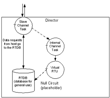
In addition to the special handling of the internal ISaGRAF RTU, the Internal Channel includes other child elements that provide special features within the system. These are the Virtual RTU, Status RTU, Segment RTU, and Internal Master. These are all connected to the Internal Channel using a "Null Circuit," which is simply a placeholder to preserve the normal Channel-Circuit-Field Unit structure. These types of field units are briefly explained here.
The Virtual RTU provides a data repository (RTDB) for internal storage of data, which is not connected with any external field device or ISaGRAF unit.
The Status RTU is another type of Virtual RTU, that can be used for storing data, but it has an additional purpose. When the RediGate is configured to poll one or more Field Devices using one or more Master Channels, there is some status information for each device such as poll count, current failed/good communication status, etc. These statistics for a whole set of Field Devices may be stored in the Modbus 40,xxx registers in the Status RTU, if desired, allowing a host system to manage communication statuses for all the field units in one place. See the section mChans Communication Status Registers for more information on field unit status values.
...
And finally, the Internal Master is a virtual RTU/RTDB definition that has the special property of being able to consolidate data from any other RTDB databases. Normally, an RTDB under any Field Unit definition only contains the data polled from that device defined in the Field Unit. The Internal Master allows one or more RTDB locations to be defined and populated with a copy of certain data points from other RTDB's. Because the RTDB is used to present data to an external master device using a Slave Channel or HCP communication link, this allows data subsets to be created.
Clients Object Placeholder
![]()
![]()
The Clients object is a placeholder for graphical clarity on the ACE tool, and provides a location to add client tasks to the configuration. Clients are generally tasks where the RediGate is initiating a connection "to" something else, such as to a field device or a network service.
| Attributes | Function |
|---|---|
| Object Type | Clients |
| Parent(s) | System |
| Instance | Must be 0 |
Master Channels Placeholder
![]()
![]()
The Master Channels Identifier is a placeholder for graphical clarity on the ACE tool, and provides a location to add specific Master Channels (data concentrators) to the configuration.
...
| Include Page | ||||
|---|---|---|---|---|
|
Database Flush (DumpRTDB_V2)
![]()
![]()
The DumpRTDB object provides a means to periodically flush all the contents of a real-time database to a system that uses report by exception (RBE), such as the Elecsys HCP or an MQTT server (MQTT RBE, JSON RBE, Sparkplug B). Normally, data is only reported upon change of state to conserve bandwidth. Flushing the database periodically requires more bandwidth, but might be preferred in cases where an additional measure of data integrity confirmation is desired. When using DumpRTDB, it is recommended to limit the size of the configured RTDB data points (RBE-enabled fields) to approximately the size of the actual number of used registers, to limit bandwitch usage to only needed data.
...
| Properties | Values |
|---|---|
| Interval Delay | Scans between RBE data refreshes. If RBE Flag parater is set to "All DBM Flags", there is one interval delay per flag (interval x 4 for each flag). |
| RBE Flag | Which RBE Flags in DBM to set |
| Device List | Select which field units to enable RBE flags. If empty, update ALL RTDB's |
HART Commands


The HART Commands object provides HART command options for mChans Field Unit HART objects' poll tables.
See the Protocol_HART-Master protocol documentation for information on configuring HART Commands.
HART Command


The HART Command object specficies a particular HART command and defines data types and registers in which to store the data in responses from HART devices.
...