3-Clients - Master Channels
- Jon Tandy
- Former user (Deleted)
Clients – Master Channels
A substantial portion of the RediGate functionality relates to its ability to act as a protocol master to third-party devices, storing data locally in internal real-time databases, and using that stored data in a variety of ways. Because of the large number of interrelated ACE objects that potentially can make up a working Master Channel, it's important to understand Master Channels at a high level before trying to learn about each object's property configuration.
In the next few sections that follow, the "Master Channel" and related capabilities are described functionally using block diagrams. After that, the remaining sub-sections describe the ACE objects and their properties that are part of the Master Channels portion of the configuration.
Master Channels Explained
The RediGate is capable of supporting many different protocol drivers, allowing it to communicate with third-party field equipment. Each type of equipment has its own unique communication protocol and data structure. The RediGate is described as a "master", because it initiates the communication to the other device.
In order to talk with the third-party equipment, a number of things need to be known about the communication network and the device. These are shown below in block diagram.
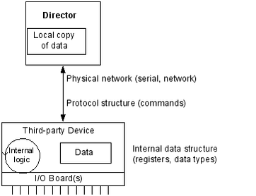
The RediGate must connect to the device (PLC, RTU, data concentrator) using some physical network – this might be over a network or a local serial port. It must send requests to the device using its native communication protocol and must request certain types of data from specified internal memory locations (registers) in the device. Once the RediGate retrieves the data from the third-party device, it stores a local copy in its internal Real-Time Databases (RTDB). From that point, other processes can use or re-transmit the data, or other host systems can request data from the RediGate.
Master/Slave Channel Functional Elements
In order for the RediGate to retrieve data from the device, the ACE configuration must include the following elements as a minimum:
- Master Channel: Defines polling sequence and timing
- Circuit: Defines which physical port to use for the connection
- Field Unit: Specifies what protocol to use and which registers to poll. Note that different Field Unit types are used depending on the third-party device protocol.
- RTDB: Defines a data area inside the RediGate in which to store data obtained from the device
In addition, the RediGate can be defined as a slave device to another master, allowing the other master to retrieve data that has been stored in the RTDB data areas. This requires one or more sets of Slave Channel elements to also be defined:
- Slave Channel: Defines slave address and protocol type used in communication to another master device.
- Slave Attach: Defines which RTDB contains data that will be made available to the master on this unit's slave address.
The normal polling sequence is as follows (numbers refer to the elements in the following diagram):
- The Master Channel generates a poll request based on its Scan Table. The Master Channel simply scans devices by address, but is not dependent on any specific communication protocol
- The Protocol Task (Field Unit definition) looks up the requested poll in its Poll Table and sends the defined command to the external device in the correct protocol format.
- The response from the device is processed and validated
- The device data is then stored into the RTDB defined for that Field Unit. This polling cycle continues based on the timing and sequence defined in the ACE configuration for the Master Channel. The RTDB typically only contains the last known value for each data point in its register locations (there are some cases where the protocol is capable of supporting event-based data).
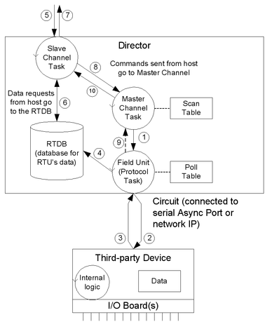
When an external master device requests data from the Slave Channel, the following sequence is observed:
- The master request is received by the Slave Channel for certain registers in the RTDB.
- The Slave Channel requests the latest value stored in these registers from the RTDB. Note that the external device is not polled directly to request data at this time, only the stored copy of last-known data in the RTDB.
- The RTDB returns data to the Slave Channel, which then returns the data to that master that requested it.
If the host sends a command via the Slave Channel to set certain register values in the device, the following sequence is observed. Note that in this case the command is typically sent on a pass-through basis directly to the device, different from the previous sequence where data is requested from the RTDB:
- The host command message is received by the Slave Channel (5), which is passed internally from the Slave Channel to the Master Channel task. The Master Channel, in turn, sends the request to the Field Unit protocol task (1), which sends a poll to the field unit (2), and waits for a valid response from the device (3).
- After receiving the response, the Field Unit protocol task notifies the Master Channel of the command's success or an invalid response. No notification is given if the command times out.
- The Master Channel passes the success or failure notification to the Slave Channel, and the Slave Channel notifies the host (7).
Note that in the foregoing command sequence, no data is returned from the Field Unit to the RTDB. If the command sent from the master included writing data to the third-party device, that data is written directly to the device and does not exist in the RTDB unless a subsequent Master Channel polling process subsequently requests it, as described above in steps 1-4.
ISaGRAF Channel Functional Elements
One of the features in the RediGate is the ability to define an ISaGRAF internal logic device (PLC) that operates as a stand-alone device within the system.
The Channel/RTU structure described in the previous section is very similar to the structure used for the ISaGRAF field unit. In this case, the RediGate uses an "Internal Channel" to communicate with the ISaGRAF field unit, whereas the Master Channel is used to communicate externally to other devices.
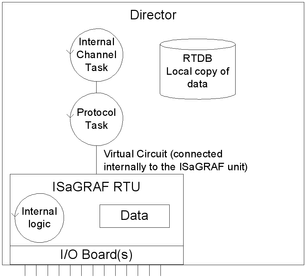
An ISaGRAF Field Unit may be thought of as a "virtual RTU". It is "virtual" because it doesn't exist as a separate device, but rather it resides inside the RediGate. As in the case of an external RTU, this ISaGRAF "virtual RTU" may contain I/O boards connected to field wiring, and may include programming logic. This is diagrammed below.
In order to preserve a logical consistency between the ISaGRAF channel and other Master Channels, an analogous structure of ACE objects is used for the Internal Channel.
Master Channel Structure | Internal Channel Structure (ISaGRAF) |
Master Channel: Defines polling sequence and timing to external devices | Internal Channel: Defines polling sequence and timing to internal |
Circuit: Defines which physical port to use for the connection (Async or Network) | Virtual Circuit: Defines a logical port to use for internal connection to ISaGRAF unit |
Field Unit: Specifies what protocol to use and which registers to poll. Note that different Field Unit definitions are used depending on the third-party device protocol. | ISaGRAF Field Unit: Specifies a specific type of field unit definition for the ISaGRAF unit, as well as which registers to poll. |
RTDB: Defines a data area in which to store data obtained from the device | RTDB: Defines data area in which to store data obtained from the ISaGRAF unit. Note that this is different from data stored internally within the ISaGRAF logic device. The RTDB is necessary if ISaGRAF data is to be used externally by other master systems or the HCP. |
In the case of a Master Channel, there are two locations where the data is stored. The external Field Unit contains certain data that are accessed using a protocol request. The RediGate contains an RTDB, which includes only the points of data obtained using the Master Channel polling.
For the ISaGRAF RTU the situation is analogous. One set of data resides inside the ISaGRAF RTU logic device and may contain any number of internal values. But only the data polled from ISaGRAF using the Internal Channel is available within the RTDB, which may be made available to other systems.
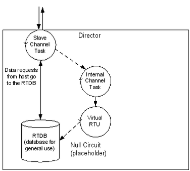
The data flow diagram for the ISaGRAF unit is shown below. Compare this with the data flow diagram for an external device (Master/Slave Channel Functional Elements).
- The Internal Channel generates a poll request based on its Scan Table.
- The ISaGRAF Protocol task (Field Unit definition) looks up the requested poll in its Poll Table and sends the defined command to the internal ISaGRAF RTU.
- The response from ISaGRAF is processed and validated
- The ISaGRAF data is then stored into the RTDB. This polling cycle continues based on the timing and sequence defined in the ACE configuration for the Internal Channel. The RTDB typically only contains the last known value for each data point in its register locations.
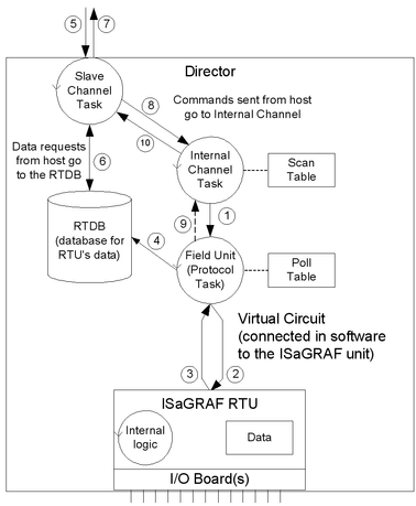
When an external master device requests data using the Slave Channel, the following sequence is observed:
- The master request is received by the Slave Channel for certain registers in the RTDB.
- The Slave Channel requests the latest value stored in these registers from the RTDB. Note that when using a generic master device, the ISaGRAF device is not polled directly to request data at this time, only the last-known value stored in the RTDB.
- The RTDB returns data to the Slave Channel, which then returns the data to that master that requested it.
If the host sends a command to the Slave Channel for ISaGRAF, the following sequence is observed. Note that in this case the command is typically sent on a pass-through basis directly to ISaGRAF, different from the previous sequence where data is requested from the RTDB:
- The host command message is received by the Slave Channel (5), which is passed internally from the Slave Channel to the Internal Channel task. The Internal Channel, in turn, sends the request to the ISaGRAF Field Unit protocol task (1), which sends a poll to the internal RTU (2), and waits for a valid response (3).
- After receiving the response, the ISaGRAF Field Unit protocol task notifies the Internal Channel of the command's success or an invalid response. No notification is given if the command times out.
- The Internal Channel passes the success or failure notification to the Slave Channel, and the Slave Channel notifies the host (7).
The ISaGRAF Workbench is one type of master that may be used with the ISaGRAF RTU. The Workbench issues special protocol messages which are passed to ISaGRAF, allowing the system designer to examine ISaGRAF internal registers, troubleshoot operation of the program, download a new ISaGRAF logic program, etc. The ISaGRAF Workbench must connect to the ISaGRAF RTU through a Slave Channel as described above in order to gain this special access to the ISaGRAF logic processing functionality. See the Elecsys ISaGRAF Manual for more information on using and programming the ISaGRAF RTU.
Other Internal Channel Functional Elements
In addition to the special handling of the internal ISaGRAF RTU, the Internal Channel includes other child elements that provide special features within the system. These are the Virtual RTU, Status RTU, Segment RTU, and Internal Master. These are all connected to the Internal Channel using a "Null Circuit," which is simply a placeholder to preserve the normal Channel-Circuit-Field Unit structure. These types of field units are briefly explained here.
The Virtual RTU provides a data repository (RTDB) for internal storage of data, which is not connected with any external field device or ISaGRAF unit.
The Status RTU is another type of Virtual RTU, that can be used for storing data, but it has an additional purpose. When the RediGate is configured to poll one or more Field Devices using one or more Master Channels, there is some status information for each device such as poll count, current failed/good communication status, etc. These statistics for a whole set of Field Devices may be stored in the Modbus 40,xxx registers in the Status RTU, if desired, allowing a host system to manage communication statuses for all the field units in one place. See the section Communication Status Registers for more information on field unit status values.
The Segment RTU is another type of Virtual RTU, which allows for a more flexible structure of data. Most Real-time Databases (RTDB) have a structure something like this (exact point types and count are configurable):
Data type | Register addresses |
Boolean | 00,001 – 00,100 |
Boolean | 10,001 – 10,100 |
UINT16 | 30,001 – 30,100 |
UINT16 | 40,001 – 40,100 |
UINT32 | 41,001 – 41,100 |
The Segment RTU allows a more heterogeneous mix of register types and point counts. Rather than large "segments" of single data types (Boolean, UINT16) as listed above for a normal RTDB, the Segment RTU allows a flexible definition such as:
Segment RTDB Instance | Register type / Count |
1 | UINT8 2 |
2 | UINT325 |
And finally, the Internal Master is a virtual RTU/RTDB definition that has the special property of being able to consolidate data from any other RTDB databases. Normally, an RTDB under any Field Unit definition only contains the data polled from that device defined in the Field Unit. The Internal Master allows one or more RTDB locations to be defined and populated with a copy of certain data points from other RTDB's. Because the RTDB is used to present data to an external master device using a Slave Channel or HCP communication link, this allows data subsets to be created.
Clients Object Placeholder
![]()
![]()
The Clients object is a placeholder for graphical clarity on the ACE tool, and provides a location to add client tasks to the configuration. Clients are generally tasks where the RediGate is initiating a connection "to" something else, such as to a field device or a network service.
| Attributes | Function |
|---|---|
| Object Type | Clients |
| Parent(s) | System |
| Instance | Must be 0 |
Master Channels Placeholder
![]()
![]()
The Master Channels Identifier is a placeholder for graphical clarity on the ACE tool, and provides a location to add specific Master Channels (data concentrators) to the configuration.
| Attributes | Function |
|---|---|
| Object Type | Master Channels |
| Parent(s) | System → Clients |
| Instance | Must be 0 |
Master Channel
![]()
![]()
The Master Channel configuration defines a "Scan Group" to a collection of field units that may be over one of the available serial or network circuits. The Master Channel defines how each field unit is scanned over the network, and is independent of which protocols are being used on individual field units.
| Attributes | Function |
|---|---|
| Object Type | Master Channel |
| Parent(s) | System → Clients → Master Channels |
| Instance | 0 to 15 (typically 15 is reserved for Internal Channels |
The Master Channel must have at least one child Circuit object defined (Async or Network).
| Properties | Values |
|---|---|
| Name | Enter the Master Channel name. This is the name which appears in the user diagnostics menu, and is also see in an HCP diagnostic window if used with Elecsys HCP. |
| Channel Type | In some configurations this may be listed as "Direct Master", which includes a few operational differences noted below. The main differences between the Channel Types are listed below: Direct Master
Direct Master Flex Scan
|
| Auto Start | Select the automatic polling method for the channel. Automatic polling types supported are:
|
| Response Timeout | Enter the response timeout in milliseconds. Time in milliseconds to wait for a poll response before declaring the message failed. For Network Circuits, if a scan fails because the socket is broken or interface is unavailable, then the Master Channel protocol will wait a period of time (Response Timeout * 2) to try the next IP address in the Circuit. |
| Broadcast Delay | Unused. |
| Interpoll delay | Enter the interpoll delay in milliseconds. Use this to add a delay between each poll sent by the channel to any field unit. Time in milliseconds to wait between each poll. |
| Scan Effective Limit | The Scan Effective Limit is the time (in seconds) defining which scans in the Scan Table are considered "effective" – meaning, polls which affect the status of the Field Unit if there are poll failures. Scan Table entries which have a Scan Period greater than the Scan Effective Limit do not mark the Field Unit offline when the scan fails. For instance, if the Scan Effective Limit is configured for 30 seconds, then any scans defined with Scan Period <= 30 will be used to mark the Field unit online or offline. Scans with Scan Period greater than 30 will not mark the Field Unit offline even if they fail. The Scan Effective Limit only applies to the "Direct Master Flex Scan Table" version of the channel object. A Scan Effective Limit of 0 disables this feature, thus all polls will affect the Field Unit status. |
| Network Recovery | Enter the network recovery period in seconds. Time period to wait after an RTU fails, before attempting to re-establish communications with that RTU. This will take the device off scan, allowing other devices on the channel to be polled more frequently and not waste as much time retrying a failed device. |
| Scan Table | Click the Edit Table button to define the order and selection of polls to be sent to all field units on this channel, independent of protocol. Field Unit configurations (Modbus, etc.) define the protocol-specific nature of the individual polls that are sent. Only one Unit Address/Poll Record combination can be entered in the Scan Table. Any subsequent table entries with duplicate Unit Address/Poll Record will be ignored. Scan Table details: Unit Address - This is the Field Unit Address as configured in each field unit on this Channel. (To force the Scan Table to ignore the Scan Period, enter a Scan Table row with the Unit Address of -1.) Poll Record - This is the row number in the Poll Record in the Field Unit definition. The first row in a Poll Table is referenced as record 1. Only those polls which are to be polled continuously need to be listed in this Scan Table. Scan Period - Enter the scan period in seconds. The Scan Period is the amount of time to use for scheduling each scan (global for all scans in the Direct Master, or configured per scan row in the Direct Master Flex Scan Table). For the Direct Master, the channel will restart the scan table sequence after the Scan Period has expired. If the total time for a given channel exceeds the scan period, the next scan shall be scheduled immediately. For the Direct Master Flex Scan Table, each poll is scheduled based on its own Scan Period. If the total time required for scans at any point is greater than allowed by the Scan Periods, the scans will operate as fast as possible. Setting a Scan Period to a negative number will disable a scan. However, the first entry in the Scan Table for each Unit Address should not be disabled, or it may not correctly set the Alive/Dead status of the unit. Comment - Optional column, allowing a descriptive comment to be entered for each row in the table. The Comment field is unused in the configuration. |
Async Circuit
![]()
![]()
An Async Circuit is a serial communications path to one or more field units from a common Master Channel, using an Async serial port. The Async Circuit allows for redundant serial ports to a common set of field units, such as a Primary and Secondary radio or modem communication path.
You should generally use a single AsyncCircuit object for a single physical serial port, and include multiple FieldUnit objects under it if they are multidropped on the same serial line. (One exception to this is when mixing serial communications with a DF1 PLC and other devices, since the DF1 has a customized circuit definition.)
| Attributes | Function |
|---|---|
| Object Type | AsyncCircuit |
| Parent(s) | System → Clients → Master Channels → Master Channel |
| Instance | Must be between 0 and 16. |
The Async Circuit should have at least one Field Unit child object defined under it.
| Properties | Values |
|---|---|
| Primary Port | Select the primary physical communication port for this circuit. The selected port must be defined as an object under Networks, where its Async port properties (baud rate, etc.) are also defined (see the section 4-Master Channel#Async Port). The same port (e.g. COM1) may also be shared with certain other tasks, such as Terminal Server, and may be used with Virtual Ports. |
Network Circuit
![]()
![]()
A Network Circuit is an IP network communications path to one or more field units from a common Master Channel. The Network Circuit is used when the field unit is connected via a network, such as TCP/IP, PPP, or SLIP.
Because of the fact that the Network Circuit includes the IP address of the end device, you will generally need to use multiple Network Circuit objects under a channel, one per device. (An exception would be a bridged device that uses a single IP address but represents multiple protocol FieldUnit devices.)
Each Network Circuit represents a TCP socket connection to a device, which is made when the Master Channel initiates a poll to the device. Each socket (one or more, if configured) is kept open independently according to the Failover Delay parameter (time to live). This avoids having to open and close sockets repeatedly to the device, as long as the scan interval is less than the Failover Delay and polls are successful.
| Attributes | Function |
|---|---|
| Object Type | NetCircuit |
| Parent(s) | System → Clients → Master Channels → Master Channel |
| Instance | Must be consecutive, starting from 0 (unique among other types of circuits). The Network Circuit should have at least one Field Unit child object defined under it. |
| Properties | Values |
|---|---|
| Circuit Type | Select the circuit type as 'Network Circuit' |
| Failover Delay | Time to Live for network socket (in seconds). Make sure this is large enough to allow for the time it takes to poll on this circuit, taking into account timeouts and interpoll delays of all scans on the channel. |
| Master Network Port | Must be consecutive, starting from 0 (unique among other types of circuits). The Network Circuit should have at least one Field Unit child object defined under it. |
| Connect Table | Click the Edit Table button to edit the IP address or list of IP addresses to connect for the Field Unit(s) on this circuit. Entering multiple IP addresses will allow failover connections when one connection fails (all connections made to the same Master Network Port on different IP addresses). Destination Address Enter the IP address to connect. The IP address must be in the same IP network or reachable via the Default Gateway or Route Table configuration. Interface Enter the network interface over which to connect to this Destination Address. The network interface must match the Interface name in the ACE object (such as "Ether1") rather than the Linux interface name (such as "eth0"). |
DF1 RS-232 Async Circuit
![]()
![]()
The DF1 RS-232 Async Circuit is a special serial communications path to one or more Allen Bradley DF1 field units from a common Master Channel. Use this circuit instead of the generic Async Circuit when configuring a DF1 field unit under a Master Channel.
See the Protocol_DF1-CSP-Master protocol documentation for information on configuring the DF1 RS-232 Async Circuit and FieldUnit.
HART Circuit

The HART Circuit object is a special serial communications path for one or more HART devices from a common master channel. Use this circuit instead of the generic Async Circuit when configuring a HART device under a Master Channel.
See the Protocol_HART-Master protocol documentation for information on configuring the HART Circuit and FieldUnit.
NMEA (GPS) Field Unit
![]()
![]()
![]() The NMEA Field Unit object contains unique information for a special internal Field Unit that reads location information from an Elecsys cellular modem.
The NMEA Field Unit object contains unique information for a special internal Field Unit that reads location information from an Elecsys cellular modem.
| Attributes | Function |
|---|---|
| Object Type | FieldUnitModbus32, FieldUnitModbusTCP32 |
| Parent(s) | System → Clients → Master Channels → Master Channel → Circuit |
| Instance | Must be unique under a channel |
The NMEA Field Unit must have an RTDB child object defined under it.
| Properties | Values |
|---|---|
| Unit Name | Enter the field unit name. Unit name is displayed in diagnostic menus and in an HCP diagnostic screen. |
| Unit Address | Enter the actual field unit address which is configured in the device being polled. Valid Modbus addresses 1 to 255. |
FieldUnit - Modbus Master (and others)
![]()
![]() – Modbus SOS (Specific Outstation) poll modifications
– Modbus SOS (Specific Outstation) poll modifications


RTDB – RealTime DataBase
![]()
![]() An RTDB (Real Time DataBase) defines the size of the virtual database reserved for the Field Unit. All FieldUnit objects require a child RTDB in order to function properly, which is defined using a numeric register address format (typically, using Modbus-like addresses).
An RTDB (Real Time DataBase) defines the size of the virtual database reserved for the Field Unit. All FieldUnit objects require a child RTDB in order to function properly, which is defined using a numeric register address format (typically, using Modbus-like addresses).
| Attributes | Function |
|---|---|
| Object Type | RtdbMod |
| Parent(s) | System → Clients → Master Channels → Master Channel → Circuit → Field Unit |
| Instance | Must be 0. |
The RTDB object supports several additional optional child objects (see the sections 4-Master Channel#Deadband , 4-Master Channel#Pre-Initialized RTDB, Tag Names, 4-Master Channel#Data Blocking, and 4-Master Channel#Timestamp).
| Properties | Values |
|---|---|
| Database Definition | Click the Edit Table button to edit the details of the RTDB definition. Point Count – Enter the number of data points of this type to be allocated space in the database. Field Format – Select the point data format: Boolean – Boolean The following field formats are the same as the above but do not generate an RBE flag when the data changes, even if the Field Unit is set to Produce RBEs=Yes. No-Rbe Boolean – Boolean Data Address – Enter the address of the starting register within the RTDB for the Field Format and Count defined on this row. Comment - Optional column, allowing a descriptive comment to be entered for each row in the table. The Comment field is unused in the configuration. |
Deadband
![]()
![]() A Deadband object defines deadbands for the data fields configured within a Real-time Database (RTDB). This is only used to reduce the communications traffic on an RBE (Report by Exception) connection. If no RBE connection is configured, an RTDB does not require a Deadband object.
A Deadband object defines deadbands for the data fields configured within a Real-time Database (RTDB). This is only used to reduce the communications traffic on an RBE (Report by Exception) connection. If no RBE connection is configured, an RTDB does not require a Deadband object.
The way the deadband works is that when a poll occurs and data is received from a Field Unit, if there is a Deadband defined for any of the points included in the poll, the current value in the RTDB is checked first. If the new values are not changed from the existing RTDB values by an amount greater than the deadband, the values are discarded and not stored in the RTDB.
| Attributes | Function |
|---|---|
| Object Type | LinuxDeadband |
| Parent(s) | System → Clients → Master Channels → Master Channel → Circuit → Field Unit → RTDB |
| Instance | Must be 0 |
| Properties | Values |
|---|---|
| Deadband | Click the Edit Table button and add as many rows as necessary to define the desired deadband values for the points in the RTDB.
|
For example, let's say the RTDB is configured with the following fields:
Point Count | Type | Data address | |
Field 1: | 100 | Boolean | 1 |
Field 2: | 100 | Boolean | 10001 |
Field 3: | 100 | UINT16 | 30001 |
Field 4: | 100 | UINT32 | 40001 |
The first four analogs at address 30,001 are 12-bit analogs that change from 0 to 4095, and we want to deadband them to report as RBE only when their values change more than 5% of their range (205). The 3rd and 4th analogs in the range starting at 40,001 we want to throttle their RBE reports to only change when the values increase or decrease by 100 and 500, respectively. All other points will be allowed to report as RBE with any single change positive or negative in their values. For this example, the Deadband table will be defined as follows:
Field | Offset | Count | Deadband | Explanation |
3 | 0 | 4 | 205 | Deadband for 30,001-30,004, 5% of its range |
4 | 2 | 1 | 100 | Deadband for 40,003 |
4 | 3 | 1 | 500 | Deadband for 40,004 |
Pre-Initialized RTDB
![]()
![]() Ordinarily, all RTDB database locations are initialized to zero values upon system startup (or zero-length strings). However, sometimes it may be desired to initialize certain database locations to a non-zero value, before any polling or other data operation occurs. Each RTDB has an optional ACE object that allows one or more registers to be initialized at startup.
Ordinarily, all RTDB database locations are initialized to zero values upon system startup (or zero-length strings). However, sometimes it may be desired to initialize certain database locations to a non-zero value, before any polling or other data operation occurs. Each RTDB has an optional ACE object that allows one or more registers to be initialized at startup.
| Attributes | Function |
|---|---|
| Object Type | PreInitRtdb |
| Parent(s) | System → Clients → Master Channels → Master Channel → Circuit → Field Unit → RTDB |
| Instance | Must be 0 |
| Properties | Values |
|---|---|
| Init Values | Click the Edit Table button to define any pre-initialized RTDB values.
|
Tag Names
![]()
![]()
RTDB database locations are configured using numeric address locations. However, the optional Tag Names child object under the RTDB allows one or more numeric address to be associated with an ASCII tag. This may be used for publishing data by tag using MQTT, for internal display using Custom Reports, and they may be used for other purposes.
| Attributes | Function |
|---|---|
| Object Type | TagNames |
| Parent(s) | System → Clients → Master Channels → Master Channel → Circuit → Field Unit → RTDB |
| Instance | Must be 0 |
| Properties | Values |
|---|---|
| Init Values | Click the Edit Table button to define any RTDB tags.
|
When publishing to MQTT, data values are published with corresponding tag name, if configured in ACE, with some exceptions (substitutions) noted below.
With MQ-RBE, Sparkplug-B, or MQ-JSON:
- If tag name includes a space, the space will be converted to an underscore _ character instead.
- The space-to-underscore conversion also applies to the Ethernet/IP master protocol.
With MQ-RBE or Sparkplug-B (not JSON):
- If tag name includes a period . it's tag will be published with a forward slash / instead.
- If tag name includes an integer between square brackets for an array (such as [23] ), it's tag will be published with the integer surrounded by forward slash and underscore instead (such as /23_ ).
- In Ignition, the forward slash in a published tag name creates a level in the collapsible tag hierarchy.
Data Blocking
![]()
![]()
The Data Blocking object allows groups of RTDB points to be blocked together for exception reporting (RBE) to an HCP. If any one point in the defined Data Block changes, all the points are reported, including the unchanged ones. If no data blocking capability is required, this object is optional.
Although it is normally recommended to store 32-bit data into 32-bit registers, Data Blocking could be used if a configuration requires 32-bit data to be stored in pairs of 16-bit registers. Each pair of registers could be defined in a separate row (count of 2), and if either value changes, the Data Block will force both registers in the pair to be reported together.
| Attributes | Function |
|---|---|
| Object Type | |
| Parent(s) | System → Clients → Master Channels → Master Channel → Circuit → Field Unit → RTDB |
| Instance | Must be 0 |
| Properties | Values |
|---|---|
| Block Definition | Click the Edit Table button to add as many rows as necessary to define the Data Block capability.
|
| Parent(s) | System → Clients → Master Channels → Master Channel → Field Unit → RTDB |
| Instance | Must be 0 |
Data Blocking does not work properly if you are using Pre-Initialized registers on the same RTDB. Blocks will be broken up at the boundaries of pre-initialized registers.
Data Blocking does not work if the blocks span discontiguous (non-sequential) register addresses in the RTDB.
Linux Timestamp
![]()
![]() A Timestamp object is used to store the time and date at which data is polled by a Master Channel. The timestamp is stored in register(s) within the RTDB, and thus may itself be reported with the RBE packet or polled via a Slave Channel.
A Timestamp object is used to store the time and date at which data is polled by a Master Channel. The timestamp is stored in register(s) within the RTDB, and thus may itself be reported with the RBE packet or polled via a Slave Channel.
Timestamps may be stored in one of two conditions whenever a specified poll occurs:
- "Always" = store timestamp whenever a poll for data occurs, even if nothing is stored in the RTDB because deadband values have not been exceeded.
- "Post-Deadband" = store timestamp only when one or more data points is stored into the database. If Deadbands are configured, data is not stored into the database until the difference between the old value and new value exceeds the configured deadband.
| Attributes | Function |
|---|---|
| Object Type | LinuxTimeStamp |
| Parent(s) | System → Clients → Master Channels → Master Channel → Circuit → Field Unit → RTDB |
| Instance | Must be 0 |
| Properties | Values |
|---|---|
| Reserved | Unused field |
| Timestamp | Click the Edit Table button to add as many rows as necessary to define the Timestamp operation. Poll Number – Enter the row number of the poll defined in the unit's Poll Table. Whenever this poll occurs for the defined points (or when any changed data points are stored in the RTDB field), a timestamp is also stored. Poll numbers start at 1. Stamp Address – Register address within the RTDB for this Field Unit in which to store the timestamp value for this poll. The Stamp Address should be the first of one or more registers with a UINT16 or UINT32 data type, and must be defined in the RTDB with the correct quantity and type. Make sure that each register or registers occupied by the timestamp are not overwritten by any other data value to avoid conflicting data. Stamp Format – Data format to use when storing data into the specified register (UINT16 or UINT32). The Stamp Format should be chosen appropriately to match the Stamp Type (below), and the data type of the RTDB register. UINT24 or UINT32 data types should be stored into a UINT32 RTDB register.
Stamp Type – Format in which to store the timestamp.
Comment - Optional column, allowing a descriptive comment to be entered for each row in the table. The Comment field is unused in the configuration. |
Internal Channel
![]()
![]() The Internal Channel configuration defines virtual field units that have several special internal purposes, including an ISaGRAF Field Unit, Status Field Unit, Virtual RTU, Segment field unit, or Internal Master. The Internal Channel configuration and its 'child' objects are similar in structure to the Master Channel and its 'child' objects, but they refer to internal databases rather than external devices being polled by a communication protocol.
The Internal Channel configuration defines virtual field units that have several special internal purposes, including an ISaGRAF Field Unit, Status Field Unit, Virtual RTU, Segment field unit, or Internal Master. The Internal Channel configuration and its 'child' objects are similar in structure to the Master Channel and its 'child' objects, but they refer to internal databases rather than external devices being polled by a communication protocol.
| Attributes | Function |
|---|---|
| Object Type | Internal Channel |
| Parent(s) | System → Clients → Master Channels |
| Instance | 0 to 15 (typically 15 is reserved for the Internal Channel, but instance 14 might also be used if a second ISaGRAF RTU is included) The Internal Channel must have at least Circuit child object defined under it. The Database Flush (DumpRTDB) object is an optional child under Internal Master. |
| Properties | Values |
|---|---|
| Name | Enter the Internal Channel name. This is the name which appears in the MMI when viewing diagnostics. |
| Channel Type | In some configurations this may be listed as "Internal Channel", which includes a few operational differences noted below. The main differences between the Channel Types are listed below: Internal Channel
Internal Channel Flex Scan
|
| Auto Start | Select from the drop down menu the automatic polling required. Automatic polling types supported are:
|
| Response Timeout | Enter the response timeout in milliseconds. This should normally be 32767 for the Internal Channel. |
| Broadcast Delay | Enter the broadcast delay in milliseconds. Delay in milliseconds after a command is sent to the ISaGRAF RTU, before normal polling resumes. |
| Interpoll Delay | Enter the interpoll delay in milliseconds. Use this to add a delay between each poll sent by the channel to the ISaGRAF unit. Time in milliseconds to wait between each poll. |
| Scan Effective Limit | The Scan Effective Limit is the time (in seconds) defining which scans in the Scan Table are considered "effective" – meaning, polls which affect the status of the field unit if there are poll failures. Scan Table entries which have a Scan Period greater than the Scan Effective Limit do not mark the Field Unit offline when the scan fails. For instance, if the Scan Effective Limit is configured for 30 seconds, then any scans defined with Scan Period <= 30 will be used to mark the Field unit online or offline. Scans with Scan Period greater than 30 will not mark the Field Unit offline even if they fail. The Scan Effective Limit only applies to the "Internal Channel Flex Scan Table" version of the channel object. |
| Network Recovery | Enter the network recovery period in seconds. Time period to wait after an RTU fails, before attempting to re-establish communications with that RTU. |
| Scan Table | Click the Edit Table button to define the order and selection of polls to be sent to the ISaGRAF Field unit on this channel. Unit Address - Enter the Modbus address of the ISaGRAF field unit to be polled. (To force the Scan Table to ignore the Scan Period, enter a Scan Table row with the unit address of -1.) Poll Record - This is the row number in the Poll Record for each poll defined for the ISaGRAF unit. The first row in a Poll Table is referenced as record 1. Only those polls which are to be scanned continuously need to be listed in this Scan Table. Scan Period - Enter the scan period in seconds. The Scan Period is the amount of time to use for scheduling each scan (global for all scans in the Internal Channel, or configured per scan in the Internal Channel Flex Scan Table). Comment - Optional column, allowing a descriptive comment to be entered for each row in the table. The Comment field is unused in the configuration. |
Do you need a Scan Table? The Internal Channel Scan Table is similar to the Master Channel, but it only refers to polls to the ISaGRAF RTU. In some cases it may not be necessary to include scans to read the ISaGRAF data. To explain why, it is necessary to examine the relationship between the ISaGRAF RTU and the RTDB.
The ISaGRAF RTU (logic, I/O, and data) exists as a separate task inside the RediGate. Similar to an external RTU, the ISaGRAF RTU contains data. In order to get this data into an RTDB, it must be scanned by the Scan Table – even though it resides inside the same hardware. The reason for this is to have a consistent Channel structure for all RTUs. For a more complete explanation, see the section 5-Internal Channel#ISaGRAF Channel Functional Elements.
If the ISaGRAF RTU does not contain data that is necessary to store in an RTDB, then it is not necessary to define any polls to the ISaGRAF RTU. As one example, the ISaGRAF logic may be written with special ISaGRAF functions such as DMOV or ISAMOV to move data from ISaGRAF or an RTDB, or from one RTDB into another. Or, the ISaGRAF logic may simply act on data from other RTDB's, such as sending a Publish message or an E-mail. In these cases, the data contained within the ISaGRAF RTU may not need to be scanned by the Internal Channel in order to read it into the ISaGRAF RTDB, and thus no Scan Table rows need to be defined.
Also note that other units under the Internal Channel (Status RTU, Virtual RTU, Segment RTU) do not need to be polled for data. They reside under the Null Circuit, and their data simply appears in their own RTDBs automatically without being scanned.
Null Circuit
![]()
![]()
A Null Circuit object defines placeholder in the configuration, under which one or more Status/Control, Virtual, Segment, or Internal Master field units are defined for an Internal Channel.
| Attributes | Function |
|---|---|
| Object Type | NullCircuit |
| Parent(s) | System → Clients → Master Channels → Internal Channel |
| Instance | Must be 0 or 1. (However, the Virtual Circuit must be instance 0, so if used with a Null Circuit, the Null Circuit must be instance 1.) |
The Null Circuit should have at least one child Filed Unit object defined under it.
| Properties | Values |
|---|---|
| Circuit Type | Placeholder for the circuit type as 'Null Circuit'. |
Virtual Field Unit
![]()
![]()
A Virtual Field Unit object allows an additional Real-time Database (RTDB) to be defined for internal storage of data. This may be used as a data repository for the ISaGRAF program logic to store data values, and/or the RTDB may serve as the source of data for a Slave Channel definition.
Note: The Virtual Field Unit will not automatically be marked alive for purposes of reporting via an MQTT client. To make sure the Virtual Field Unit is marked alive, one of the following needs to be done:
- In the Internal Master Channel, define one scan for the Virtual unit (use Poll Record 1). Make sure the Scan Period is very long (longer than the Scan Effective Limit). Even though the poll will be marked as a timeout, the Virtual Unit will be marked alive because the Scan Table completes its cycle.
- In the Internal Master Channel, if there is an Internal Master unit being scanned in addition to the Virtual unit, the Virtual unit will also be marked as alive. (This occurs because the Channel is required to complete one full scan cycle successfully.)
- Or you could use a POD "SET RTU STATUS" or ISaGRAF 'setosval' function to set the Virtual unit to an alive state.
| Attributes | Function |
|---|---|
| Object Type | FieldUnitVirtual |
| Parent(s) | System → Clients → Master Channels → Internal Channel → NullCircuit |
| Instance | Must be between 0 and 255, and should be unique under this Null Circuit among all Status, Virtual, and Internal Master field units. |
| Properties | Values |
|---|---|
| Unit Name | Enter the field unit name as an identifier for the Field Unit. |
| Unit Address | Enter the Field Unit address. This should be a unique address from any other ISaGRAF, Status, or Internal Master field unit addresses on this Internal Channel. The default address is 3. |
| Protocol | Placeholder for field unit protocol type 'Repository Database Unit'. |
| Com Retries | This parameter is a null field to retain compatibility with other field unit objects. The only option is 'N/A'. |
| Comm Status Holdreg | Enter the starting holding register to contain the communication status for this field unit. Typically, this field is unused for the Virtual Unit. Each Comm Status takes 5 registers, beginning at the register configured in this parameter. The Comm Status Holdreg for each field unit in a configuration must be defined such that the five registers do not overlap other registers being used. If the register is defined in the 30,xxx address range, the status values will be stored in the local device's RTDB (i.e., the RTDB defined as a child object to this ISaGRAF Field Unit. If the register is in the 40,xxx range, the values will be stored in the Status/Control Field Unit RTDB. The Comm Status Holdreg is optional, and can be set to 0 to disable the storage of status registers. See the section 5-Internal Channel#Communication Status Registers, for a description of the five Comm Status Register contents. |
| Produce RBEs | Select this option to determine whether to produce a Report by Exception (RBE) flag when data in this unit's RTDB changes. In the RTDB, for every data point, there are potentially 4 RBE flags associated with every data point. When the data point changes, the RBE flags are set. These flags are used to determine when new data needs to be reported to the HCP. |
| No Polls | This parameter is a null field to retain compatibility with other field unit objects. The only option is 'N/A'. |
Internal Master Field Unit
![]()
![]()
The Internal Master is a special type of Field Unit which is designed to provide an easy mechanism for collecting and consolidating data from any other Field Unit RTDBs into the RTDB associated with the Internal Master unit. In theory, it operates like a Master Channel Field Unit, which polls data from an external device; but the Internal Master operates only to take data from one RTDB to another.
| Attributes | Function |
|---|---|
| Object Type | FieldUnitInternalMast |
| Parent(s) | System → Clients → Master Channels → Internal Channel → NullCircuit |
| Instance | Must be between 0 and 256, and should be unique under this Null Circuit among all Status, Virtual, and Internal Master field units. The Internal Master Field Unit should have a 5-Internal Channel#Modbus RTDB child object defined under it (see page ). |
| Properties | Values |
|---|---|
| Unit Name | Enter the field unit name. |
| Unit Address | Enter the field unit address. This should be a unique address from any other ISaGRAF, Status, Virtual, or Internal Master field unit addresses on the Internal Channel. The default address is 5. |
| Protocol | Select the Protocol type for the Internal Master field unit. The Protocol selection determines the rules by which a host can access the data in this Virtual Master's RTDB, via attachment to a Slave Channel. Available Protocol types are:
|
| Com Retries | Enter the number of communication retries after a failed poll attempt. If a poll attempt fails, poll will be sent again up to the configured number of "Com Retries" before the field unit is declared failed. |
| Comm Status Holdreg | Enter the starting holding register to contain the communication status for this field unit. Each Comm Status takes 5 registers, beginning at the register configured in this parameter. The Comm Status Holdreg for each field unit in a configuration must be defined such that the five registers do not overlap other registers being used. If the register is defined in the 30,xxx address range, the status values will be stored in the local device's RTDB (i.e., the RTDB defined as a child to this Field unit). If the register is in the 40,xxx range, the values will be stored in the Status/Control Field Unit RTDB. The Comm Status Holdreg is optional, and can be set to 0 to disable the storage of status registers. See the section 5-Internal Channel#Communication Status Registers, for a description of the five Comm Status Register contents. |
| Produce RBEs | Select this option to determine whether to produce a Report by Exception (RBE) flag when data in this unit's RTDB changes. In the RTDB, for every data point, there are potentially 4 RBE flags associated with every data point. When the data point changes, the RBE flags are set. These flags are used to determine when new data needs to be reported to the HCP. |
| Poll Table | Click the Edit Table button to define the Modbus polls to be sent to this unit. Note that the Poll Table only defines how the Modbus protocol is defined to operate for each set of data defined in the polls. The Poll Table doesn't actually do any of the polling itself. If you want any of these polls to be sent to the Field Unit on a regular basis, it should be referenced in one or more Scan Table entries in the Master Channel. Src Chan – Enter the Channel number of the RTDB containing the source data. This is either a Master Channel or Internal Channel instance number that must be defined under the Master Channels placeholder. Src RTU – Enter the Field Unit number of the RTDB containing the source data. This is the Unit Address configured in the properties of the field unit, not the instance number of the field unit ACE object, if they are different. Src Data – Enter the source register number for the starting register in the Field Unit's RTDB to begin retrieving data. Src Type - Enter the data type of the data being requested. See below for a discussion of Src Type options in the Master Channel. Src Count – Enter the number of registers to retrieve. The maximum number allowed in any poll is the same as for Modbus polls: 500 Boolean registers, 125 registers of 16-bit type, or 62 registers of 32-bit type. The Count includes the number of register values being requested, starting at the Src Data register. Dest Data – Enter the starting destination register within this Internal Master's RTDB to place the polled data. Ensure that there is a large enough quantity of registers in the RTDB to store the count. The destination register type should be chosen based on the Source Format of the data. Booleans should be stored into Boolean RTDB registers. 16-bit values should be stored into 16-bit RTDB registers. 32-bit values or 16-bit pair values should be stored into 32-bit RTDB registers. |
Discussion on Source Type
Several Src Type options are provided in the Internal Master Field Unit. These provide a number of unique capabilities for copying and transforming data from one RTDB location to another.
The following table gives a list of the Internal Master Src Type options, and an explanation of how they are used.
Src Type | Source data | Dest data | Meaning |
|---|---|---|---|
Boolean | Boolean | Boolean | Single on/off bit occupies a register |
8 bit | Take lower 16-bits of an integer register. | ||
16 bit | 16 bit | 16 bit | Typical 16-bit register type. |
24 bit | 32-bit | 32-bit | Take lower 3 bytes of a 32-bit integer register |
32 bit | 32 bit | 32 bit | |
Short String | STRING32 | STRING32 | |
Long String | STRING256 | STRING256 | |
UTF String | |||
Event | |||
Double-Float | 64 bit | 64 bit | |
Copy 16-Bit pairs into 32-Bit Regs | 16 bit | 32 bit | Registers are taken as pairs, and the Src Count should be the numbers of pairs of registers (32-bit entities). (Source registers are little-endian.) |
Swap 16-Bit pairs into 32-Bit Regs | 16 bit | 32 bit | Registers are taken pairs, and the Src Count should be the numbers of pairs of registers (32-bit entities). (Source registers are big-endian.) |
Split-Copy 32-bit Regs into 16-bit-Pair Regs | 32 bit | 16 bit | 32-bit register is broken into pairs of 16-bit registers |
Split-Swap 32-bit Regs into 16-bit-Pair Regs | 32 bit | 16 bit | same as above, but swapped |
Boolean-Src to 16-Bit-Dest Hi to Lo Bits | Boolean | 16 bit | Boolean source registers are taken in groups of 16, with the first register becoming the most-significant bit (MSB) in the 16-bit value. NOTE: writing to the 16-bit analog register is not supported. |
16-Bit-Src to Boolean-Dest Hi to Lo Bits | 16 bit | Boolean | 16 bits in source register(s) are placed sequentially to Boolean registers, in the order of most-significant bit (MSB=1st destination register) to least-significant bit in each 16-bit word. For both Boolean-Bit data types, writing to individual RTDB Boolean registers is not supported -- any bit which is written individually will set only that bit and clear all the others. |
16-Bit-Src to Boolean-Dest Lo to Hi Bits | 16 bit | Boolean | 16 bits in source register(s) are placed sequentially to Boolean registers, in the order of least-significant bit (LSB=1st destination register) to most-significant bit in each 16-bit word. |
Note that the Boolean-Bit and Bit-Boolean data type conversions support multiple quantities of 16-bit registers, but do not support 32-bit registers.
The following source types reverse the direction of data from the other types listed above, allowing data to be copied from the Internal Master RTDB to a different Field Unit's RTDB location. Be sure to keep in mind that for these data types, the "Src" (source) and "Dest" (destination) data locations are reversed. Thus:
Src Chan/RTU/Data are the destination locations to store data in the other Field Unit.
Dest Data is the source RTDB location in the Internal Master field unit.
The source and destination data types should be the same.
Src Type | Meaning |
Trigger Move Data from Local to Src Data | Choose this option to copy data from the Internal Master RTDB (Dest Data location) into another RTDB (Src Data location), based on a trigger value. The Trigger register is the last register in the specified set. |
Trigger Write Data from Local Data to Src Chan/RTU | Choose this option to write data from the Internal Master RTDB to a device on a Source Channel/RTU address, based on a trigger value. The Trigger register is the last register in the specified set. |
Always Move Data from Local to Src Data | Choose this option to constantly copy data from the Internal Master RTDB (Dest Data location) into another RTDB (Src Data location). No trigger register is used. |
Always Write Data from Local Data to Src Chan/RTU | Choose this option to constantly write data from the Internal Master RTDB (Dest Data location) to a device on a Source Channel/RTU address/Src Data register whenever this poll is scanned by the Internal Master Channel. No trigger register is used. |
The final Internal Master "Source Type" is a special function that tells the Internal Master process to run a POD logic routine. This POD program is run in the sequence of the scans that are triggered by the Internal Master. The POD program must complete before the Scan Table can move on to the next scan.
Run POD | [ Src Count ] Src Count Column value is Pod_Index. Each POD has a unique instance number, and when this Poll Table entry is trigged, the numbered POD routine runs in its entirety before control is returned to the Internal Channel for running subsequent polls. |
The POD object in the ACE configuration holds a set of programming instructions which can be used to manipulate or make decisions on data stored in RTDBs. Up to 9999 POD modules can be configured per Internal Master Channel, which are called by a Poll Table of an Internal Master RTU (which in turn is triggered by a Scan Table entry in the Internal Master Channel).
Status Field Unit
![]()
![]()
A Status Field Unit object may be used to contain unique information for internal communication diagnostics. Field units defined under Master Channels and the ISaGRAF field unit contain a parameter for storing communication status (Comm Status Register). If the Comm Status Register for any Field Unit is configured with a starting address in the 40,xxx address range, its status values are stored in the RTDB defined for this Status Field Unit. This allows all communication status information to be stored in one place, if desired in the system design.
However, if the Comm Status Register for any Field Unit is defined with a starting address in the 30,xxx address range, the communication status values for that device are stored in the RTDB for that Field Unit rather than the common Status Field Unit RTDB. In that case, the Status Field Unit is not necessary and may be omitted from the configuration.
See the section 5-Internal Channel#Communication Status Registers for a description of the communication status registers stored for Field Units.
| Attributes | Function |
|---|---|
| Object Type | FieldUnitSysCtrl |
| Parent(s) | System → Clients → Master Channels → Internal Channel → NullCircuit |
| Instance | Must be between 0 and 255, and should be unique under this Null Circuit among all Status, Virtual, and Internal Master field units. Only one Status Field Unit should be included in a configuration. |
The Status Field Unit should have a 5-Internal Channel#Modbus RTDB child object defined under it (see page ).
| Properties | Values |
|---|---|
| Unit Name | Enter the field unit name as an identifier. |
| Unit Address | Enter the field unit address. This should be a unique address from any other ISaGRAF, Virtual, or Internal Master field unit addresses on the Internal Channel. |
| Protocol | Placeholder for field unit protocol type 'System Control & Status Unit'. |
| Com Retries | This parameter is a null field to retain compatibility with other field unit objects. The only option is 'N/A'. |
| Comm Status HoldReg | This parameter is a null field to retain compatibility with other field unit objects. It should be set to 0. |
| Produce RBEs | Select this option to determine whether to produce a Report by Exception (RBE) flag when data in this unit's RTDB changes. In the RTDB, for every data point, there are potentially 4 RBE flags associated with every data point. When the data point changes, the RBE flags are set. These flags are used to determine when new data needs to be reported to the HCP. |
| No Polls | This parameter is a null field to retain compatibility with other field unit objects. The only option is 'N/A'. |
Communication Status Registers
The section 5-Internal Channel#Status Field Unit describes the Status Control RTU, which stores communication statuses for field units. The five status values contain the following data for each unit:
1st Register
Bit 0,1,2 Communication status to field unit. A register value of 0 indicates failed communication, and 7 indicates good communication..
Bit 7 Unit is disabled.
2nd Register Percent (%) Communication throughput to field unit. Throughput = (Total Polls - # Timeouts - # Bad Data polls) / Total Polls. Range is 0 - 1000 scaled, so that a value of 987 = 98.7 %.
3rd Register Total Polls. Total number of polls sent since last restart. When this register reaches 65,000 it rolls over to zero, and the 2nd, 4th, and 5th status bytes are also reset to zero.
4th Register # Timeouts. Number of polls receiving no response since last reset.
5th Register # Bad Data polls. Number of CRC or data errors to polls since last reset.
The RTDB for the Status/Control field unit must include an adequate number of holding registers to contain all the Comm Status registers for all defined Field Units, and these 5 Comm Status registers for each device must not overlap each other.
Segment Field Unit
![]()
![]()
A Segment Field Unit object allows Segment databases (RTDB) to be defined with a more flexible structure than most RTDBs. Like the Virtual unit, the Segment Field Unit is simply a data repository and does not require any Internal Channel scans to be defined. The Segment unit is used to create a more granular list of registers with a mix of different data types.
| Attributes | Function |
|---|---|
| Object Type | FieldUnitSegment |
| Parent(s) | System → Clients → Master Channels → Internal Channel → NullCircuit |
| Instance | Must be between 0 and 255, and should be unique under this Null Circuit among all Status, Virtual, and Internal Master field units. |
| Properties | Values |
|---|---|
| Unit Name | Enter the field unit name as an identifier for the Field Unit. |
| Unit Address | Enter the Field Unit address. This should be a unique address from any other ISaGRAF, Status, Virtual, or Internal Master field unit addresses on this Internal Channel. |
| Protocol | Placeholder for field unit protocol type 'Segment Database Unit'. |
| No Comms | Unused |
| Not Used | Unused |
| No Polls | Unused |
Segment RTDB
![]()
![]()
A Segment RTDB (Real Time DataBase) defines the size of the virtual database reserved for the Segment Field Unit. The Segment RTDB contains some significant differences from other RTDB objects. It is more flexible in size and construction, and multiple Segment RTDBs may be configured under a single Segment Field Unit. The Segment RTDB also allows deadbands to be defined in the database by point number, rather than through a separate field-based Deadband object.
There are several ISaGRAF functions that allow data to be pushed and retrieved from a Segment point index, to publish a particular Segment RTDB, etc.
The collection of Segment RTDB objects together create a single RTDB as might exist under other Field Unit objects. The Segment RTDB is indexed with only a Point Count, not requiring a register address to be configured. The table below shows the comparison between a set of Segment RTDB objects as compared with a similarly configured RTDB for other field units.
| Src Type | Source data | Dest data | Meaning |
|---|---|---|---|
Boolean | Boolean | Boolean | Single on/off bit occupies a register |
8 bit | Take lower 16-bits of an integer register. | ||
16 bit | 16 bit | 16 bit | Typical 16-bit register type. |
24 bit | 32-bit | 32-bit | Take lower 3 bytes of a 32-bit integer register |
32 bit | 32 bit | 32 bit | |
Short String | STRING32 | STRING32 | |
Long String | STRING256 | STRING256 | |
UTF String | |||
Event | |||
Double-Float | 64 bit | 64 bit | |
Copy 16-Bit pairs into 32-Bit Regs | 16 bit | 32 bit | Registers are taken as pairs, and the Src Count should be the numbers of pairs of registers (32-bit entities). (Source registers are little-endian.) |
Swap 16-Bit pairs into 32-Bit Regs | 16 bit | 32 bit | Registers are taken pairs, and the Src Count should be the numbers of pairs of registers (32-bit entities). (Source registers are big-endian.) |
Split-Copy 32-bit Regs into 16-bit-Pair Regs | 32 bit | 16 bit | 32-bit register is broken into pairs of 16-bit registers |
Split-Swap 32-bit Regs into 16-bit-Pair Regs | 32 bit | 16 bit | same as above, but swapped |
Boolean-Src to 16-Bit-Dest | Boolean | 16 bit | Boolean source registers are taken in groups of 16, with the first register becoming the most-significant bit (MSB) in the 16-bit value. |
16-Bit-Src to Boolean-Dest | 16 bit | Boolean | 16 bits in source register(s) are placed sequentially to Boolean registers, in the order of most-significant bit (MSB=1st destination register) to least-significant bit in each 16-bit word. |
The instance number and point count for each Segment RTDB implicitly defines the data addresses that can be used when referring to data values in the Segment RTU. Note that the registers in Segment RTDBs are defined in blocks of (multiples of) 300 points per instance number. If one Segment# includes more than 300 points, as with Segment #2 in the above example, you must not skip those Segment RTDB instance numbers to avoid an address conflict.
| Attributes | Function |
|---|---|
| Object Type | RtdbSegmentFdb |
| Parent(s) | System → Clients → Master Channels → Internal Channel → NullCircuit → FieldUnitSegment |
| Instance | Must be between 1 and 255. |
| Properties | Values |
|---|---|
| Produce RBEs | Select this option to determine whether to produce a Report by Exception (RBE) flag when data in this unit's RTDB changes. In the RTDB, for every data point, there are potentially 4 RBE flags associated with every data point. When the data point changes, the RBE flags are set. These flags determine when new data needs to be reported to an MQTT server, HCP, or other hosts supporting RBE. |
| Segment Definition | Click the Edit Table button to edit the details of the RTDB definition. Point Count – Enter the number of data points of this type to be allocated space in the database. Point Format – Select the point data format:
Deadband – Enter the deadband value for the points defined on this row, which is the amount a value in the RTDB can change before it will be flagged as an RBE. Deadband value is entered as an integer or floating point value, which is handled as a 15-character (max) string. If IEEE floating point format is used, its entry must include a decimal point (such as 11.0). Comment - Optional column, allowing a descriptive comment to be entered for each row in the table. The Comment field is unused in the configuration. |
DirectorPOD
![]()
![]() Elecsys provides a separate manual to describe how PODs are configured and to explain each of the many function codes available. See the RediGate POD Programming Manual for further instructions.
Elecsys provides a separate manual to describe how PODs are configured and to explain each of the many function codes available. See the RediGate POD Programming Manual for further instructions.
Virtual Circuit
![]()
![]()
A Virtual Circuit object defines an internal communications path to one ISaGRAF field unit from an Internal Channel. The Virtual Circuit is simply a placeholder, designed to match the operation of a normal Async Circuit.
| Attributes | Function |
|---|---|
| Object Type | VirtualCircuit |
| Parent(s) | System → Clients → Master Channels → Internal Channel |
| Instance | Must be 0 |
The Virtual Circuit should have one ISaGRAF Field Unit child object defined under it.
| Properties | Values |
|---|---|
| Circuit Type | Placeholder for circuit type of 'Virtual Circuit'. |
ISaGRAF Field Unit
![]()
![]()
An ISaGRAF Field Unit object is used to run a protocol task that allows an ISaGRAF logic program to run in the RediGate, and defines parameters for how data is read from and written to the ISaGRAF unit.
The RediGate allows for running two independent ISaGRAF logic programs simultaneously. In this case, the Internal Channels should be defined as instance numbers 14 and 15, with each channel including a Virtual Circuit and ISaGRAF Field Unit objects. In either case, to allow the ISaGRAF Workbench program to download and monitor the ISaGRAF logic program(s), the ISaGRAF Field Unit definition must be attached to a Slave Channel definition. See the section 5-Internal Channel#Slave Channels for setting up the Slave Channel.
| Attributes | Function |
|---|---|
| Object Type | FieldUnitIsagraf |
| Parent(s) | System → Clients → Master Channels → Internal Channel → VirtualCircuit |
| Instance | Must be 0 |
The ISaGRAF Field Unit should have a 5-Internal Channel#Modbus RTDB child object defined under it (see page ).
| Properties | Values |
|---|---|
| Unit Name | Enter the field unit name. Unit name is displayed in diagnostic menus and in an HCP diagnostic screen. |
| Unit Address | Enter the actual field unit address which will be used for the ISaGRAF Field Unit. This Modbus unit address will be referenced under a Slave Channel, from which the ISaGRAF workbench will communicate to the logic program. This should be a unique address from any other Status, Virtual, or Internal Master field unit addresses on the Internal Channel. Valid addresses 1 to 255. Typically address 1 is used for one ISaGRAF unit (often configured in Channel 15), but if using two ISaGRAF RTUs in the same configuration one of them must be configured for address 123. |
| Protocol | Placeholder for the protocol type as 'IsaGraf Logic Unit'. |
| Com Retries | Enter the number of communication retries after a failed poll attempt. If a poll attempt fails, it will try again up to the configured number of "Com Retries" before the field unit is declared failed. |
| Comm Status Holdreg | Enter the starting holding register to contain the communication status for this field unit. Each Comm Status takes 5 registers, beginning at the register configured in this parameter. The Comm Status Holdreg for each field unit in a configuration must be defined such that the five registers do not overlap other registers being used. If the register is defined in the 30,xxx address range, the status values will be stored in the local device's RTDB (i.e., the RTDB defined as a child object to this ISaGRAF Field Unit. If the register is in the 40,xxx range, the values will be stored in the Status/Control Field Unit RTDB. The Comm Status Holdreg is optional, and can be set to 0 to disable the storage of status registers. See the section 5-Internal Channel#Communication Status Registers, for a description of the five Comm Status Register contents. |
| Produce RBEs | Select this option to determine whether to produce a Report by Exception (RBE) flag when data in this unit's RTDB changes. In the RTDB, for every data point, there are potentially 4 RBE flags associated with every data point. When the data point changes, the RBE flags are set. These flags are used to determine when new data needs to be reported to the HCP. |
| Poll Table | Click the Edit Table button to define the Modbus polls to be sent to this ISaGRAF field unit. Note that the Poll Table only defines how the Modbus protocol is defined to operate for each set of data defined in the polls. The Poll Table doesn't actually do any of the polling itself. If you want any of these polls to be sent to the ISaGRAF Field Unit on a regular basis, it should be referenced in one or more Scan Table entries in the Internal Channel. Source Register – Enter the source register in the ISaGRAF RTU to begin polling data. This will be a Modbus register defined on an I/O board definition in the ISaGRAF logic program. Source Format – Enter the data type of the data being requested. See below for a discussion of Source Format options. See the section Modbus/Open Modbus TCP Field Unit for a full discussion on Source Formats. For the ISaGRAF RTU, typically the following Source Formats should be used:
Count – Enter the number of registers to poll. Destination Register – Enter the starting destination register within the RTDB (Real Time Data Base) to place the polled data. Comment - Optional column, allowing a descriptive comment to be entered for each row in the table. The Comment field is unused in the configuration. |
Load/Store ISaGRAF Defaults
![]()
![]()
The Load/Store object defines a separate download file, containing parameter values used by the ISaGRAF STORE16 and STORE32 boards. The STORE boards are pseudo boards containing variables that are stored in the Flash file system (see the Elecsys ISaGRAF Manual for more details on these boards).
When an entry in the STORE16 or STORE32 board is written (or a variable attached to one of the STORE boards), ISaGRAF automatically creates a file in the file system with the name lsaabbcccc (first character is the letter "L"), where aabbcccc is identical to the ISaGRAF file isaabbcccc. Defining the Load/Store object in the ACE configuration defines default values to be stored in the STORE board if it doesn't already exist. This allows the ISaGRAF application to be written generically, and yet to act differently for individual units based on the device-specific values contained in STORE boards, as configured in the ACE Load/Store object.
After the lsaabbcccc file is created or downloaded to the RediGate, its values may be changed by the ISaGRAF program operation. Downloading the file from ACE again would overwrite any values that have subsequently been stored in the LoadStore file.
| Attributes | Function |
|---|---|
| Object Type | LoadStore |
| Parent(s) | System → Clients → Master Channels → Internal Channel → VirtualCircuit → FieldUnitIsagraf |
| Instance | Must be 0 |
| UFF External | Checkbox should be enabled. |
| Properties | Values |
|---|---|
| Parameter Table | Click the Edit Table button to edit the default values contained in the Load/Store parameter table. Parameter 1 through Parameter 16 – Enter the value for each parameter defined in the ISaGRAF STORE16 or STORE32 board. Multiple rows defined in the Parameter Table correspond to multiple sequential instances of the STORE boards (in the order of instances defined in the ISaGRAF application). Comment - Optional column, allowing a descriptive comment to be entered for each row in the table. The Comment field is unused in the configuration. When uploading the ACE configuration, the |
TextStore Object
![]()
![]()
A TextStore object defines a separate download file in the configuration, containing default text strings which may be read and used by the ISaGRAF program logic. The TextStore file is created with the name staabbcccc, where aabbcccc is identical to the ISaGRAF file isaabbcccc to which it is attached.
This allows an ISaGRAF program to be written that can take user-configured text entries that are specific to each RediGate. This allows the ISaGRAF application to be written generically, and yet to act differently for individual units based on the device-specific text values contained in TextStore boards, as configured in the ACE Load/Store object.
After the staabbcccc file is created or downloaded, its values may be changed by the ISaGRAF program operation. Downloading the file from ACE again would overwrite any values that have subsequently been stored in the TextStore file.
| Attributes | Function |
|---|---|
| Object Type | TextStore |
| Parent(s) | System → Clients → Master Channels → Internal Channel → VirtualCircuit → FieldUnitIsagraf |
| Instance | Must be 0 |
| UFF External | Checkbox should be enabled. |
| Properties | Values |
|---|---|
| Text Table | Click the Edit Table button to edit the default values of the TextStore object. Text – Enter the text for each field. The text fields are limited to 16 characters per string. Comment - Optional column, allowing a descriptive comment to be entered for each row in the table. The Comment field is unused in the configuration. When uploading the ACE configuration, the |
Database Flush (DumpRTDB_V2)
![]()
![]()
The DumpRTDB object provides a means to periodically flush all the contents of a real-time database to a system that uses report by exception (RBE), such as the Elecsys HCP or an MQTT server (MQTT RBE, JSON RBE, Sparkplug B). Normally, data is only reported upon change of state to conserve bandwidth. Flushing the database periodically requires more bandwidth, but might be preferred in cases where an additional measure of data integrity confirmation is desired. When using DumpRTDB, it is recommended to limit the size of the configured RTDB data points (RBE-enabled fields) to approximately the size of the actual number of used registers, to limit bandwitch usage to only needed data.
| Attributes | Function |
|---|---|
| Object Type | DumpRTDB |
| Parent(s) | System → Clients → Master Channels |
| Instance | Must be 0 |
| Properties | Values |
|---|---|
| Interval Delay | Scans between RBE data refreshes. If RBE Flag parater is set to "All DBM Flags", there is one interval delay per flag (interval x 4 for each flag). |
| RBE Flag | Which RBE Flags in DBM to set |
| Device List | Select which field units to enable RBE flags. If empty, update ALL RTDB's |
HART Commands


The HART Commands object provides HART command options for Field Unit HART objects' poll tables.
See the Protocol_HART-Master protocol documentation for information on configuring HART Commands.
HART Command


The HART Command object specficies a particular HART command and defines data types and registers in which to store the data in responses from HART devices.
See the Protocol_HART-Master protocol documentation for information on configuring HART Commands.