Protocol_HART-Master
- Former user (Deleted)
- Former user (Deleted)

Product Information
Full information about other Elecsys products is available on our website at www.elecsyscorp.com and the RediGate Product Support page.
Product Support
Tel: +1-913-890-8905
Fax: +1-913-982-5766
Email: idc-support@elecsyscorp.com
Headquarters, Sales, Support & Manufacturing
Elecsys Corporation
846 N Mart-Way Court
Olathe, KS 66061
Tel: +1-913-647-0158
Fax: +1-913-982-5766
Email: info@elecsyscorp.com
While Elecsys may assist customers with their choice of products, the final choice of product for a specific application is entirely the responsibility of the buyer. Elecsys' entire liability with respect to its products or systems is defined in the Elecsys standard terms and conditions of sale.
Any example code is provided only to illustrate the use of Elecsys products. No warranty, either expressed or implied, is made regarding any example code provided by Elecsys and Elecsys shall incur no liability whatsoever arising from any use made of this code.
Disclaimers
The information in this manual is believed to be accurate at the time of publication. Elecsys Corporation assumes no responsibility for inaccuracies that may be contained in this document and makes no commitment to update or keep current the information contained in this manual. Elecsys Corporation assumes no responsibility for any infringements of patents or other rights of third parties that may result from its use. Elecsys Corporation reserves the right to make changes or improvements to this document and/or product at any time and without notice. While Elecsys may assist customers with their choice of products, the final choice of product for a specific application is entirely the responsibility of the buyer. Elecsys' entire liability with respect to its products or systems is defined in the Elecsys standard terms and conditions of sale.
Any example code is provided only to illustrate the use of Elecsys products. No warranty, either expressed or implied, is made regarding any example code provided by Elecsys and Elecsys shall incur no liability whatsoever arising from any use made of this code.
Electrostatic Discharge (ESD) Protection
These units contain devices that could be damaged by the discharge of static electricity. At all times, please observe industry standard ESD precautions when handling the unit.
 WARNING: DO NOT CONNECT OR DISCONNECT CABLES WHEN ENERGIZED, UNLESS POWER HAS BEEN REMOVED FROM THE EQUIPMENT OR THE AREA IS KNOWN TO BE FREE OF IGNITABLE CONCENTRATIONS OF FLAMMABLE SUBSTANCES.
© 2024 Elecsys Corporation
Table of Contents
Introduction
The RediGate Configuration Manual describes the configuration of many of the RediGate's standard features using the ACE program. This document gives additional instructions for configuring the RediGate to use the following protocols:
- HART Master
See the following Quick Start example configurations:
The RediGate is a multi-application remote data communications computer/data integration device. It provides a wide array of SCADA and other communication and logic processing functionality. In order to configure the operational characteristics of the RediGate, Elecsys provides the ACE Configuration Editor. This manual assumes that the user is already familiar with the use of ACE and that the RediGate being configured includes software support for the above protocols.
Within the ACE Editor, each configuration object is represented by an icon and contains general properties and specific fields that provide operational settings for the RediGate. This manual provides reference information on the configuration objects within the ACE Editor, specific to the FieldUnit protocol(s) listed above.
HART Protocol Description
This document is not intended to provide a detailed description of the protocol(s) involved, nor to disclose proprietary information that may belong to other parties. Depending on the protocol, it may be necessary to refer to other vendor protocol documentation or device configuration details to understand how the RediGate should be configured to interface with it. This section provides a brief discussion of the protocol for the purpose of understanding the RediGate's configuration objects.
HART® (Highway Addressable Remote Transducer) and WirelessHART® registered trademarks of the HART Communication Foundation, Austin, Texas, USA (http://www.hartcomm.org). The HART Communication Foundation owns and manages the specification for the HART protocol. HART was designed to leverage compatibility with traditional 4-20 mA analog devices, while adding a low-power digital communication layer that allows for enhanced data acquisition and operational capabilities. HART digital signaling uses a 1200 bps Frequency-Shift-Keying (FSK) small amplitude current superimposed on the relatively low-frequency 4-20 mA analog current signal. HART protocol communication typically involves using a modem that translates the 1200 baud FSK signal from the current loop (seen as voltage across a low impedance loop resistor) to a serial port of a microcontroller, such as the RediGate. (There is also provision for a C8PSK physical layer that can transmit at up to 9600 bps.)
HART is a master-slave protocol and may include read or write operations. The HART specification defines three categories of commands:
- Universal Commands – must be implemented by all HART compatible devices according to specification.
- Common Practice Commands – optional, standardized commands that must be used according to specification when implemented.
- Device Specific Commands – commands defined by device manufacturers according to individual device requirements.
Traditionally, HART devices were addressed by a numeric Short Address from 0 to 15. Address 0 indicates the transmitter is in 4-20 mA current signaling mode, while addresses 1-15 indicate the device is in multi-drop mode (with a fixed analog current, and all device data is obtained via the digital protocol). Devices may also be queried using the device's Tag name instead of the Short Address. The structure of a HART message is shown below:
| Preamble | Start Character | Address | Command | Byte Count | Status | Data | Checksum |
- Preamble is three or more bytes of hexadecimal 0xFF characters allowing the receiving modem to synchronize its frequency detection circuit.
- Start Character has various values depending on the frame format used and source of the message.
Master to slave (0x02 for short frame message, 0x82 for long frame)
Slave to master (0x06 for short frame message, 0x86 for long frame) - Address contains the field device address for the message in either single byte form (short frame) or five bytes (long frame). MSB indicates whether the host is a primary master (1) or secondary master (0).
- Command indicates which HART command is being transmitted.
- Byte Count indicates total number of bytes in the Status and Data portions of the message.
- Status (2 bytes) is only present in a slave response and indicates various status conditions of the device. The RediGate stores the Status bytes into an RTDB register.
- Data may be empty or contain relevant data bytes depending on the command request or reply. The Data portion of the message is important to understand when configuring the RediGate, because each HART command must be defined in the RediGate configuration, with data fields mapped to RTDB registers.
- Checksum is a single byte XOR (longitudinal parity) of all preceding bytes beginning with the Start Character.
The following sections describe the ACE objects used for HART Master, object properties (including constraints on the Instance number), and object fields and their possible values required to configure for the given protocol(s). The object structure in ACE is hierarchical, with each object existing under a certain parent object. For instance, the FieldUnit is the child of one of several types of Circuit objects, either serial or network type (" System>Clients>Master Channels>Master Channel>Circuit").
The Description and Enabled properties are included in ACE as part of each object but are not mentioned here. The "UFF External" property is only mentioned for the objects where it is typically used, but should normally be left unchecked.
HART Master Channel
The structure of ACE objects for a Master Channel used for HART protocol is shown below. Note the configuration must include the special HartCircuit and one or more HartCommand objects:
| HART Serial |
|
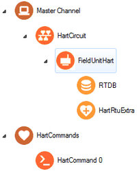
The RediGate uses the Master Channel and its child objects to define the RediGate's ability to act as a master for reading or writing other devices using one or more device protocols. All master protocols use the same basic structural definition, requiring at least four ACE objects to be configured:
- The Master Channel defines the sequence and timing of periodic scans of the device, independent of protocol.
- The Circuit (network or serial) defines the physical connection to the device.
- The FieldUnit object defines the protocol-specific characteristics and poll definitions for the device.
- The Real-time Database (RTDB) defines a data structure for storing information obtained from each physical field device.
- Other optional child objects under the RTDB or FieldUnit provide other features for acting on the device's data.
In the Master Channel configuration, make sure that the Response Timeout is set long enough to receive replies for the given network and field devices. Add rows in the Scan Table for each poll in each FieldUnit that is required to be scanned in real-time.
For general information on configuring Master Channels, see the RediGate Configuration Manual.
In the HART FieldUnit's Poll Table, every command must be included that is intended to be supported by the RediGate. But as with all other FieldUnit types, it is not required to scan all of those polls in real-time. For instance, a typical Poll Table is shown below that includes seven polls defined in the HART Command objects.

Although the Poll Table might contain many Command Index entries, the Master Channel might be configured to poll only for the 3rd Poll Record (CMD 03 - Read PVs as floating point), as shown below. This allows the primary process variables to be read continuously for each of the configured HART devices.
Note that a Scan Period of 0 milliseconds (and also Response Timeout and Interpoll Delay of 0) is used to obtain the maximum HART scan rate, but actual communication delays are determined by built-in timing required by the HART protocol, which makes the effective scan rate about 2-3 polls per second. Any non-zero Scan Period or Interpoll Delay will add additional poll delay beyond the timing required by the HART protocol, and a non-zero Response Timeout will increase delay on timeouts.
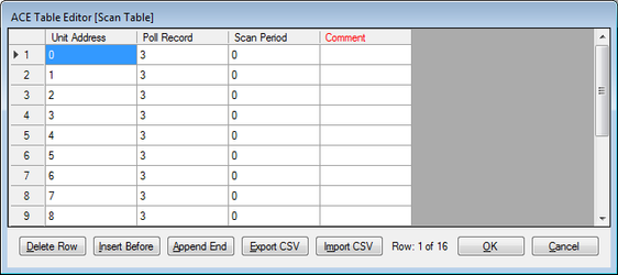
Although in the example above the Master Channel is only scanning for HART CMD 03 continuously, the other polls in the HART FieldUnit's Poll Table may be requested on demand using the device's Command Register (see HART RTU Extra).
HART Circuit


The HART Circuit object is a special communications path for one or more HART devices from a common master channel. Use this circuit instead of the generic Async Circuit when configuring a HART device under a Master Channel.
| Attributes | Function |
|---|---|
| Object Type | HartCircuit |
| Parent(s) | System → Clients → Master Channels → Master Channel |
| Instance | Must be between 0 and 16. |
The HART Circuit should have at least one Field Unit HART child object defined under it.
| Properties | Values |
|---|---|
| Circuit Type | Hart Circuit |
| Primary Port | Select the COM port that the HART modem is connected to |
| Reserved1 | Reserved for future use |
| Reserved2 | Reserved for future use |
AsyncPort


Make sure to include an COM port (System → Networks → AsyncPort) object in the configuration with the instance number matching the physical COM port, and the baud rate corresponding to the field device’s setting. For a port connected to a HART modem device, the settings of the AsyncPort should typically be:
Properties | Values |
|---|---|
| Baud Rate | 1200 |
| Parity | Odd |
| Word Length | 8 |
| Stop Bits | 1 |
| Rx Buffer Size | For the RediGate 100 series using an external HART modem, use "RS-232". For the RediGate 400, this setting is unused. |
| Tx Buffer Size | Unused. |
| Warm Up Time | 5 |
| Warm Down Time | 5 |
See the RediGate Configuration Manual for information on configuring the AsyncPort.
HART Field Unit


The FieldUnitHART object is used to configure polling of a particular HART device that is on a HART circuit.
| Attributes | Function |
|---|---|
| Object Type | FieldUnitHart |
| Parent(s) | System → Clients → Master Channels → Master Channel → HART Circuit |
| Instance | Must be between 0 and 16. |
The FieldUnit must have an RTDB and should also typically have a HART RTU Extra child object defined under it.
Before defining the Poll Table, you must also define one or more HART Command objects.
| Properties | Values |
|---|---|
| Unit Name | Unit name identifying the HART device. If the Unit Address field is set to a number >100, the RediGate will poll the HART device based on its configured Unit Name (Tag). In this case, the Unit Name field should be no longer than 8 characters. If the Unit Address is <100, the RediGate will poll the HART device by its numeric address, and the Unit Name field is only used for internal identification, MQTT publishing, etc. |
| Unit Address | Unit address of the HART device on the network. Typically, the Unit Address will be 0 through 15. However, to poll by HART Tag name, set the Unit Address to a unique number greater than 100. See the Unit Name property above for instruction on configuring for Poll by Tag. |
| Protocol | Hart Unit |
| Com Retries | Enter the number of communication retries after a failed poll attempt. If a poll attempt fails, the RediGate will issue the poll again up to the configured number of "Com Retries" before the field unit is declared failed. For devices on a Network Circuit, you should probably keep the number of protocol retries low (0 or 1), because TCP/IP has its own network retries. |
| Comm Status Holdreg | Enter the starting holding register to contain the communication status for this FieldUnit. Each Comm Status takes 5 registers, beginning at the register configured in this parameter. The Comm Status Holdreg for each field unit in a configuration must be defined such that the five registers do not overlap other registers being used. If the register is defined in the 30,xxx address range, the status values will be stored in the local device's RTDB (i.e., the RTDB defined as a child to this FieldUnit). If the register is in the 40,xxx range, the values will be stored in the Status/Control Field Unit RTDB. The Comm Status Holdreg is optional, and can be set to 0 to disable the storage of status registers. See the section Communication Status Registers in the RediGate Configuration Manual for a description of the five Comm Status Register contents. |
| Produce RBEs | Select this option to determine whether to produce a Report by Exception (RBE) flag when data in this unit's RTDB changes. In the RTDB, for every data point, there are potentially 4 RBE flags associated with every data point. When the data point changes, the RBE flags are set. The RediGate's HCP and MQTT publishing processes use these flags to determine when new data needs to be reported. |
| Poll Table | Click the Edit Table button to define the polls to be sent to this FieldUnit. Note that the Poll Table only defines how the protocol is defined to operate for each set of data defined in the polls. The Poll Table doesn’t actually do any of the polling itself. If you want any of these polls to be sent to the FieldUnit on a regular basis, it should be referenced in one or more Scan Table entries in the Master Channel. Poll Table entries may be defined which are only used for pass-through writing to the device, not scanned regularly by the Master Channel. Protocol-specific properties for the Poll Table are described in the following table. The Poll Table references the list of Hart Command objects created elsewhere in the configuration, mapping the bytes of the HART commands into RTDB register addresses. |
| Poll Table Properties | |
|---|---|
| Properties | Values |
| Command Index | Select one of the HART Commands on each row of the Poll Table. The list of HART Commands in this list is dynamic, depending on the ACE objects defined under HART Commands. |
| Comment | The Comment column is an optional field, allowing a description to be entered for each row in the table. This is only for the user and has no effect on the operation of the RediGate. |
HART RTU Extra


The HART RTU Extra object
A Modbus FieldUnit object contains unique information for each physical field device that uses the Modbus communication protocol, defining parameters for how data is read and written for the device.
| Attributes | Function |
|---|---|
| Object Type | HartRtuExtra |
| Parent(s) | System → Clients → Master Channels → Master Channel → HART Circuit → FieldUnitHart |
| Instance | Must be 0. |
| Properties | Values |
|---|---|
| Command Register | The Command Register is an integer register in the HART FieldUnit RTDB which is used to request the RediGate to send a HART command on demand. To force a command in this device's Poll Table to be executed on demand, write into the Command Register the Poll Record row number of the poll to request. Note that the Command Register is the Poll Record number, not the actual HART command number. It is therefore recommended to configure the Poll Table for similar HART devices to be in an identical order, to avoid confusion over which Command Register value to use. After a command is operated by writing to the Command Register, the resulting value in the Command Register indicates what was the result of the previous command, which may be read and acted on by a host system or internal RediGate logic. The result values that appear in the Command Register are:
|
| Response Register | The Response Register is an integer register in the HART FieldUnit RTDB that will contain the two Command Status bytes included in each response from a HART device. The least-significant byte (LSB) in the Response Register contains the Field Device Status (2nd byte of HART Status):
The next most-significant byte (MSB) in the Response Register contains the 1st byte of the HART Status. This is either a command-specific Response Code, or a communication or command response error.
|
| #Timeouts to Identify | Enter the number of communication timeouts before the RediGate will revert to an Identity command to identify the HART device again. This should typically be a low number (default is 5). The polling logic for the HART master protocol is:
|
| Reserved | Unused property |
HART Commands


The HART Commands object is a placeholder, under which one or more HART Command objects will be included.
| Attributes | Function |
|---|---|
| Object Type | HartCommands |
| Parent(s) | System → Clients → Master Channels |
| Instance | Must be 0 |
HART Command


The HART Command object specficies a particular HART command and defines data types and RTDB registers in which to store the data used in communication with the HART device. HART Command objects are dynamically referenced by HART Field Unit Poll Tables. The name of the object is what is shown in the dropdown list of the Field Unit HART → Poll Table → Command Index column.
| Attributes | Function |
|---|---|
| Object Type | HartCommands |
| Parent(s) | System → Clients → Master Channels → HartCommands |
| Instance | Must be between 0 and 256 |
| Properties | Values |
|---|---|
| Hart Command | HART command number as defined in the HART protocol (universal, common practice, or device-specific). |
| Definition Table | This object defines the Data Type of fields associated with the particular HART command, and RTDB addresses in which to store the values returned from or sent to the device. Data fields must be included in this table in the order in which the bytes occur in the HART Data message. If more Data bytes are received from a device than are referenced in this table, they are automatically discarded. Similarly, if the HART Command definition includes more bytes than are included in the actual HART message, command processing will cease when the bytes run out. Data Type: Choose the correct datatype associated with the selected Action (Store, Discard, or Write) in order to parse bytes from the HART command message.
Action: Select one of three actions for processing bytes in HART command messages. Read and Store: This action takes the response from the HART command and stores the data (whose type is defined by the selection in the "Data Type" column) in the RTDB address starting at the specified "Address" location. Read and Discard: This action takes the response from the HART command and does not store it in any RTDB register (discards the bytes). Write Data: This action is used for commands written to a HART device. Data is taken from the RTDB address starting at the specified "Address" location and builds an output message to the device according to the Data Type and Count. The values are sent in the order in which these "Write Data" entries are defined in the Definition Table for the command. Count: Enter the number of sets of HART command Data to process according to the Data Type and Action specified. Address: Enter a starting RTDB address register in which to store the bytes identified by Data Type format. For Write actions, the RediGate will use the current values in the registers to create the Data messages sent to the device. For Read and Discard actions, the Address field is unused but must be set to a value of at least 40001. Comment: The Comment column is an optional field, allowing a description to be entered for each row in the table. This is only for the user and has no effect on the operation of the RediGate. |
Examples of HART Command Definitions
The definition of a HART Command within the ACE configuration requires knowledge of the command structure (Data portion only), as published by the HART Communication Foundation or manufacturer device-specific command documentation. Several examples are given below.
HART Command 3 – Read Dynamic Variables and Loop Current
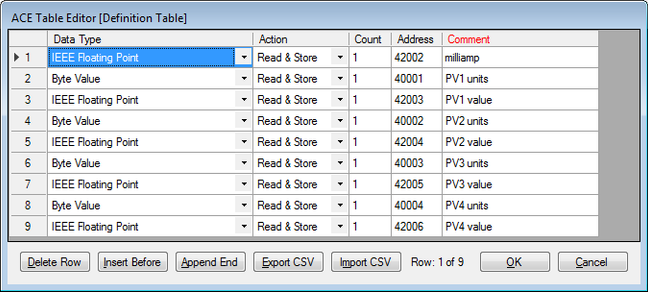
HART universal command #3 returns the loop current and up to four process variables with their engineering units codes (the 2nd, 3rd, and 4th variables are optional). Documentation for command #3 describes the following Data structure:
Request Data Bytes
| Byte | Format | Description |
| None | (i.e., the Request for HART command #3 includes no bytes in the Data portion of the message) |
Response Data Bytes
| Byte | Format | Description |
| 0-3 | Float | Primary Variable Loop Current (mA) |
| 4 | Enum | Primary Variable Units Code |
| 5-8 | Float | Primary Variable (floating point, in engineering units) |
| 9 | Enum | Secondary Variable Units Code |
| 10-13 | Float | Secondary Variable |
| 14 | Enum | Tertiary Variable Units Code |
| 15-18 | Float | Tertiary Variable |
| 19 | Enum | Quaternary Variable Units Code |
| 20-23 | Float | Quaternary Variable |
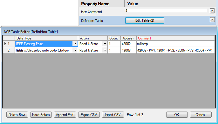
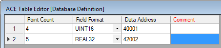
To create a HART Command definition in ACE that will read up to four process variable and the milliamp current (but discard the unit codes), a Command definition would be constructed as shown below. The minimum required RTDB configuration is also shown. This command would be scanned in the Master Channel using the Unit Address of the device (as configured in ACE) and the Poll Record number (row number of this HART Command in the device's Poll Table).

However, as a variation on the example, to poll and store all four process variables, milliamp current, and the units codes into the RTDB registers, a different HART Command and additional RTDB registers would need to be defined, as shown below:
HART Command 0 – Read Unique Identifier
Although the RediGate automatically uses HART command #0 (or #11) to identify the device initially, so that Command #0 doesn't need to be defined in the HART Command objects, it may still be valuable to define a Command #0 to be polled as data that can be stored into the RTDB. Command #0 includes device information that might be important to acquire in order to report to a host system.
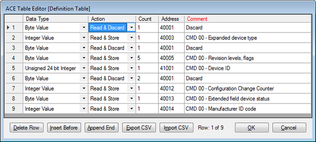
Below is an example HART Command definition for command #0. In this example, there are no request (Write) Data fields. Response data bytes are processed as shown in the following bullets:
- Byte 0 – discard
- Bytes 1-2 → 40003 (expanded device type, Integer type reads 2 bytes)
- Byte 3 → discard
- Byte 4 → 40005 (HART revision number)
- Byte 5 → 40006 (Device revision level)
- Byte 6 → 40007 (Software revision level)
- Byte 7 → 40008 (Hardware revision level, physical signaling code)
- Byte 8 → 40009 (Flags)
- Bytes 9-11 → 41001 (Device ID, three bytes stored to UINT32 register)
- Bytes 12-13 → discard
- Bytes 14-15 → 40012 (Configuration change counter)
- Byte 16 → 40013 (Extended device status)
- Bytes 17-18 → 40014 (Manufacturer ID code)
Some older devices won't have bytes 17 and 18, so the command processing will end after all available Data bytes have been processed. Other devices will have additional bytes 19 through 21, which will be automatically discarded, because they aren't included in the HART Command definition in the RediGate.
HART Command 18 – Write Tag, Descriptor, Date
This example shows the definition of a command that writes data to the HART device. HART command #13 reads the 8-character Tag, 16-character Descriptor, and a 3-byte Date code. HART Command #18 writes these values from the RTDB to the HART device and reads the same data back into the RTDB from the device response. The example configuration shown below uses the following registers:
- Bytes 0-5 – Registers 41002-41003 (two 32-bit integers)
- Bytes 6-17 – Registers 41004-41007 (four 32-bit integers)
- Bytes 18-20 – Register 41008 (uses three of the four bytes from 32-bit integer)
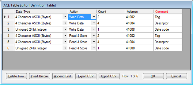
To trigger the operation of HART Command 18, first set the new Tag, Descriptor, and Date code into registers 41002-41008. Then write the Poll Index (row number in the Poll Table) of the command into the Command Register of the HART FieldUnit.
HART Command 6 – Write Short Address
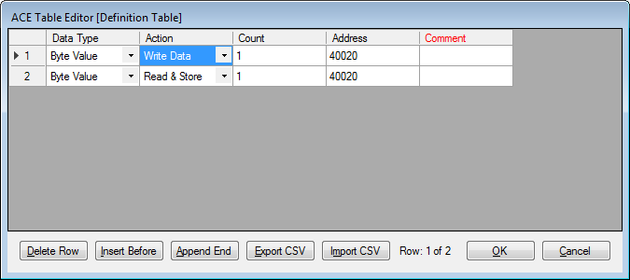
This example shows the definition of a command that sets the Short Address of a HART device. An example configuration is shown below. Enter a new Short Address (0-15) into register 40020, then write the Poll Index (row number in the Poll Table) of the command into the Command Register of the HART FieldUnit.