DF1 Over Ethernet to RediGate Master
- Jon Tandy
- Former user (Deleted)
Introduction
In this tutorial, we will be demonstrating connectivity from a RediGate 120C to an SLC 5/05 over Ethernet using the DF1 protocol. This tutorial can be used to for connecting and RediGate with a device-level Ethernet port to any DF1 enabled Allen-Bradley PLC (MicroLogix, SLC, or PLC-5). For setting up communication over EtherNet/IP to CompactLogix and ControlLogix PLCs, see the "EtherNet/IP to RediGate Master" guide.
Pre-Requisites
- A RediGate 120X or 400 series device with an open Ethernet port
- Completion of the Getting Started Guide for your respective RediGate device (RediGate 100 or RediGate 400)
- An Ethernet connection to a DF1/PCCC enabled PLC. You will need to configure your RediGate's local Ethernet port to be on the same network as the PLC, and you should confirm that you are able to ping the PLC through that port.
Instructions
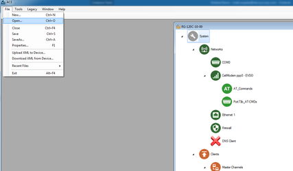
- Using ACE, open the default config you used in the "Getting Started Guide"
Download and open the Elecsys-DF1-Demo.zip from the Example Configurations page.
- You will need to extract the .xml file from the .zip file you downloaded from the website. By default, ACE stores configuration files in the Documents\Elecsys\ACE\CFG folder, but you can store the configuration in any file location accessible by the ACE program..
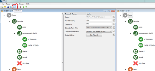
- Open the XML configuration within the same ACE window as the configuration you used in your "Getting Started Guide." You cannot copy/paste nodes unless both configurations are open within the same instance of ACE. You can use the "Tile" buttons to have the windows automatically size themselves within the ACE program:
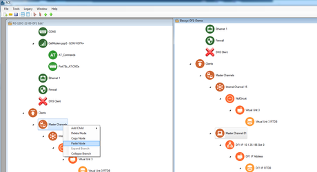
- Copy the "MasterChannel01" channel from the Elecsys-DF1-Demo.xml and paste the node into your configuration:
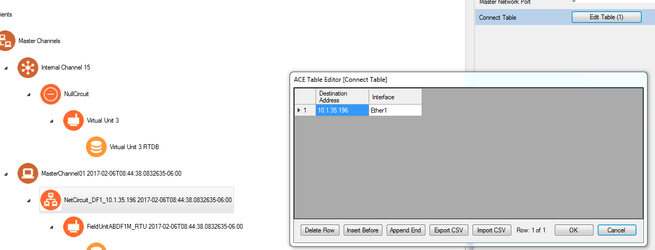
- Edit the "NetCircuit_DF1_10.1.35.196" → Connect Table to have the IP address of the PLC you will be connecting to. Do not worry about the "Interface" column; it is only used for legacy protocols.
- Under the "FieldUnitABDF1M_RTU" object, edit the "Poll Table" to poll the correct registers on your PLC:
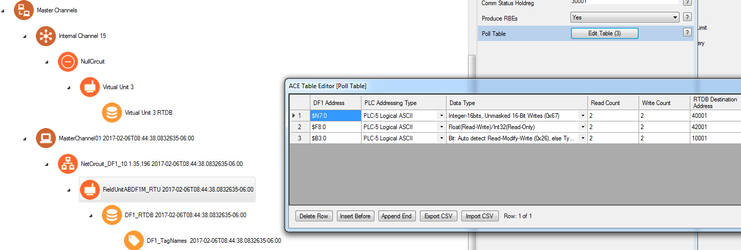
In the screenshot above, we are polling $F8:0 for a count of 2 and storing the data starting in the RTDB address of 42001: in the next step we will create the database of registers that are used to store these polled values.
Polling registers that do not exist
You must have data in the registers that you are polling, otherwise you receive errors on that poll record during that poll attempt. For example, there are only 2 $F8 registers declared in this PLC program:
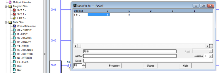
Attempting to poll register $F8:2 will result in an error.
- Edit the DF1_RTDB → Database Definition table so that it contains enough registers of the correct datatypes to store all of the polls created in the previous step:
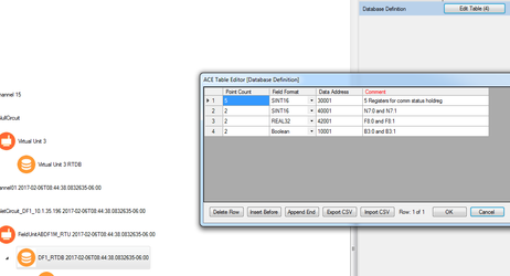
- In the above example, 5 registers were created in 30001 for the status bits coming from the RTU object, and 2 registers were created for the integers, floats, and bools we are polling
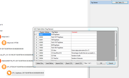
- Edit the "DF1_TagNames → Tag Names" table to add tag names for the registers you are polling:
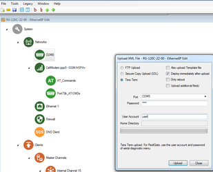
- Save and upload the configuration to the RediGate (File → Upload XML to Device)
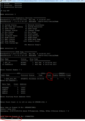
- Create a Putty session into the RediGate to confirm that the RediGate is successfully polling the tags. You may get some errors on start-up, but if you see the Poll Count field incrementing, your RediGate is configured correctly.
Congratulations, you have successfully configured your RediGate to talk to an Ethernet DF1 device. If you are interested in publishing your data to a cloud IoT platform, download one of our "IIoT Platform Quick Starts" from Example Configurations.