Protocol_EtherNetIP-Master
- Former user (Deleted)
- Jon Tandy

Product Information
Full information about other Elecsys products is available on our website at www.elecsyscorp.com and the RediGate Product Support page.
Product Support
Tel: +1-913-890-8905
Fax: +1-913-982-5766
Email: idc-support@elecsyscorp.com
Headquarters, Sales, Support & Manufacturing
Elecsys Corporation
846 N Mart-Way Court
Olathe, KS 66061
Tel: +1-913-647-0158
Fax: +1-913-982-5766
Email: info@elecsyscorp.com
While Elecsys may assist customers with their choice of products, the final choice of product for a specific application is entirely the responsibility of the buyer. Elecsys' entire liability with respect to its products or systems is defined in the Elecsys standard terms and conditions of sale.
Any example code is provided only to illustrate the use of Elecsys products. No warranty, either expressed or implied, is made regarding any example code provided by Elecsys and Elecsys shall incur no liability whatsoever arising from any use made of this code.
Disclaimers
The information in this manual is believed to be accurate at the time of publication. Elecsys Corporation assumes no responsibility for inaccuracies that may be contained in this document and makes no commitment to update or keep current the information contained in this manual. Elecsys Corporation assumes no responsibility for any infringements of patents or other rights of third parties that may result from its use. Elecsys Corporation reserves the right to make changes or improvements to this document and/or product at any time and without notice. While Elecsys may assist customers with their choice of products, the final choice of product for a specific application is entirely the responsibility of the buyer. Elecsys' entire liability with respect to its products or systems is defined in the Elecsys standard terms and conditions of sale.
Any example code is provided only to illustrate the use of Elecsys products. No warranty, either expressed or implied, is made regarding any example code provided by Elecsys and Elecsys shall incur no liability whatsoever arising from any use made of this code.
Electrostatic Discharge (ESD) Protection
These units contain devices that could be damaged by the discharge of static electricity. At all times, please observe industry standard ESD precautions when handling the unit.
 WARNING: DO NOT CONNECT OR DISCONNECT CABLES WHEN ENERGIZED, UNLESS POWER HAS BEEN REMOVED FROM THE EQUIPMENT OR THE AREA IS KNOWN TO BE FREE OF IGNITABLE CONCENTRATIONS OF FLAMMABLE SUBSTANCES.
© 2024 Elecsys Corporation
Table of Contents
Introduction
The RediGate Configuration Manual describes the configuration of many of the RediGate's standard features using the ACE program. This document gives additional instructions for configuring the RediGate to use the following protocol:
- Rockwell Automation/Allen Bradley EtherNet/IP (EIP/CIP) Master
The EtherNet/IP master will communicate with ControlLogix, CompactLogix, and MicroLogix-820 PLCs. See the following Quick Start example configuration:
To communicate with PLC5, SLC50x, or MicroLogix-1xxx PLCs, you will need to use the DF1 protocol instead.
The RediGate is a multi-application remote data communications computer/data integration device. It provides a wide array of SCADA and other communication and logic processing functionality. In order to configure the operational characteristics of the RediGate, Elecsys provides the ACE Configuration Editor. This manual assumes that the user is already familiar with the use of ACE and that the RediGate being configured includes software support for the above protocols.
Within the ACE Editor, each configuration object is represented by an icon and contains general properties and specific fields that provide operational settings for the RediGate. This manual provides reference information on the configuration objects within the ACE Editor, specific to the FieldUnit protocol(s) listed above.
EtherNet/IP Protocol Description
This document is not intended to provide a detailed description of the protocol(s) involved, nor to disclose proprietary information that may belong to other parties. Depending on the protocol, it may be necessary to refer to other vendor protocol documentation or device configuration details to understand how the RediGate should be configured to interface with it. This section provides a brief discussion of the protocol for the purpose of understanding the RediGate's configuration objects.
The Ethernet/IP protocol (EIP/CIP, an adaptation of Common Industrial Protocol, managed by ODVA) uses an object-oriented data model and employs both TCP/IP and UDP/IP as the transport protocols. An EtherNet/IP-compliant PLC or device will be configured with CIP objects having data that is typically defined in structures that may contain a mix of different data types and are typically identified by tag names. This differs from many other protocols supported by the RediGate, which commonly use a register-based data format. The RediGate's Poll Table is able to read CIP objects from the PLC and parse them into Real-time Database (RTDB) registers using the appropriate data types.
This document does not describe configuration of Allen Bradley DF1 or CSP protocols. The RediGate does not currently support Data Highway Plus (DH+), which requires a special hardware interface.
The following sections describe the ACE objects used for DF1 and CSP Master, object properties (including constraints on the Instance number), and object fields and their possible values required to configure for the given protocol(s). The object structure in ACE is hierarchical, with each object existing under a certain parent object. For instance, the FieldUnit is the child of one of several types of Circuit objects, either serial or network type (" System>Clients>Master Channels>Master Channel>Circuit").
The Description and Enabled properties are included in ACE as part of each object but are not mentioned here. The "UFF External" property is only mentioned for the objects where it is typically used, but should normally be left unchecked.
Supported Features and Limitations of EtherNet/IP Master
CIP objects may contain complex arrays and nested structures of data organization. In order to simplify the process of creating RediGate configurations, Elecsys provides a tool for converting the PLC configuration file (L5X) into the tables necessary for configuring the Scan Table, Poll Table, RTDB, and TagName tables.
The RediGate supports many standard features of EtherNet/IP, including:
Supported Data Types
RediGate can read the following Atomic data types: Bit, Int-8, Int-16, Int-32, Int-64, Real-32. A String is considered a structure.
RediGate can read the following Pre-defined Data Types (PDTs) of: TIMER, COUNTER, CONTROL, ALARM_ANALOG, ALARM_DIGITAL, PID, and STRING.
RediGate can read and write single data elements, arrays (single-dimensional only), UDT/PDT structures (up to 4000 bytes), array of Atomic elements within a structure, or a single structure within a structure (one level deep only).
UNsupported Data Types
RediGate currently cannot read PDTs that include ENCODED_DATA, MESSAGE, MODULE, ROUTINE, CONNECTION, PROGRAM, MOTION_GROUP, MOTION_INSTRUCTION, and AXIS.)
RediGate does not support structures within structures more than one level deep, and does not support an array of structures inside a structure.
- Top-level arrays of structures will be read with one structure per poll. Groups of Atomic tags are scanned ten per transaction.
For example, a simple array of 10 timers, TimerArray[10], will execute ten separate polls of TimerArray[0] to TimerArray[9]. - When reading large arrays, they will be broken into multiple blocks of 460 bytes.
- Item tag names are imported from the L5X file. RediGate does not support automatic discovery of tags.
- Data writes to Bit arrays are done by first reading 32 Boolean values from the RTDB, masking in the new values, and then writing all 32 Booleans to the PLC's 32-bit word.
Following are some additional limitations of the EtherNet/IP Master in the RediGate:
- If elements are added or removed from a UDT structure, you should go through the L5X Import Tool to re-import the four tables into ACE (Scan Table, Poll Table, RTDB, TagNames, rather than modifying the tables by hand.
- Implicit messaging (unsolicited data from device using RPI cycle time) via UDP is not supported.
- Only peer-to-peer, single-level communications are allowed. No tunneling is allowed through PLCs to other PLCs, networks, or protocols using the EtherNet/IP master driver.
- The EtherNet/IP Master is unable to identify "Local:1" physical I/O items. The PLC program must create tags or aliases for each I/O point required in the polling communication.
If an external Modbus host is reading PLC data from the RediGate using a Modbus Slave Channel, then there are special requirements for the organization of RTDB registers (see the "Modbus Slave Attach" section of the RediGate Configuration Manual).
Using the L5X Tool
See the Ethernet/IP Master Quick Start documentation for instructions on setting up a demo configuration to poll an EtherNet/IP device.
See Using the L5K Import Tool for brief instructions on using the ACE Configuration Management Utility to select PLC tags.
Or see Elecsys ACE Management Utility for more detailed instructions on using the ACM utility.
EtherNet/IP Master Channel
The structure of ACE objects for a Master Channel used for the EtherNet/IP protocol is shown below:
| EtherNet/IP Master |
|
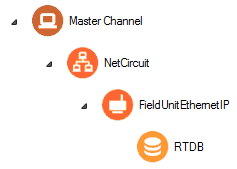
The RediGate uses the Master Channel and its child objects to define the RediGate's ability to act as a master for reading or writing other devices using one or more device protocols. All master protocols use the same basic structural definition, requiring at least four ACE objects to be configured:
- The Master Channel defines the sequence and timing of periodic scans of the device, independent of protocol.
- The Circuit (network or serial) defines the physical connection to the device.
- The FieldUnit object defines the protocol-specific characteristics and poll definitions for the device.
- The Real-time Database (RTDB) defines a data structure for storing information obtained from each physical field device.
- Other optional child objects under the RTDB or FieldUnit provide other features for acting on the device's data.
In the Master Channel configuration, make sure that the Response Timeout is set long enough to receive replies for the given network and field devices. Add rows in the Scan Table for each poll in each FieldUnit that is required to be scanned in real-time.
For general information on configuring Master Channels, see the RediGate Configuration Manual.
Note the following when configuring the Master Channel for EtherNet/IP devices:
- Response Timeout needs to be set greater than the Scan Period - this is because the RediGate uses the Response Timeout to notify the EtherNet/IP PLC of what period it should expect to be polled (or else the PLC may shut down its open socket prematurely).
- The Scan Table should be imported using the L5X Import tool in the ACM Utility. The PLC polling setup can get somewhat complicated, so it is not recommended to modify the table by hand.
- If the configuration includes more than one EtherNet/IP device, either configure them under different Master Channels, or under separate Network Circuits.
Network Circuit


A Network Circuit is an IP network communications path to one or more field units from a common Master Channel. The Network Circuit is used when the field unit is connected to the RediGate over a TCP/IP network.
To configure the Network Circuit for an EtherNet/IP PLC:
- Use Master Network Port = 44818.
- Set the Circuit Type to be "Network Circuit."
- Set the Connect Table to the IP address of the PLC.
See the RediGate Configuration Manual for information on configuring the NetCircuit object.
EtherNet/IP FieldUnit

An EtherNet/IP FieldUnit object contains unique information for each Field Unit using the EtherNet/IP communication protocol, and defines parameters for how data is read and written for the device.
If the PLC includes mixed data types, the RediGate uses a technique called "continuation polls" to optimize polling data. This method allows for one row in the Poll Table to be defined as the actual "poll" that requests data from the PLC, and subsequent rows (with Read Count=0) simply parse the data sequentially from the response obtained in the original poll.
The Continuation Poll may be used either to poll a structure, or it may be used to poll a block of Atomic elements that aren't in a structure. See the Poll Table description and Examples of EtherNet/IP Polls below for more details.
| Attributes | Function |
|---|---|
| Object Type | FieldUnitEthernetIP |
| Parent(s) | System → Clients → Master Channels → Master Channel → NetCircuit |
| Instance | Must be unique under a Circuit. |
| The Field Unit must have an RTDB child object defined under it. | |
| Properties | Values |
|---|---|
| Unit Name | Enter the field unit name. Unit name is displayed in diagnostic menus, in HCP diagnostic screens, and may be used as part of an MQTT topic name. |
| Unit Address | Enter a unique field unit address under the Master Channel. |
| Protocol | Placeholder for Protocol type of Ethernet-IP Master'. |
| Com Retries | Enter the number of communication retries after a failed poll attempt. If a poll attempt fails, the RediGate will issue the poll again up to the configured number of "Com Retries" before the field unit is declared failed. For devices on a Network Circuit, you should probably keep the number of protocol retries low (0 or 1), because TCP/IP has its own network retries. |
| Comm Status Holdreg | Enter the starting holding register to contain the communication status for this FieldUnit. Each Comm Status takes 5 registers, beginning at the register configured in this parameter. The Comm Status Holdreg for each field unit in a configuration must be defined such that the five registers do not overlap other registers being used. If the register is defined in the 30,xxx address range, the status values will be stored in the local device's RTDB (i.e., the RTDB defined as a child to this FieldUnit). If the register is in the 40,xxx range, the values will be stored in the Status/Control Field Unit RTDB. The Comm Status Holdreg is optional, and can be set to 0 to disable the storage of status registers. See the section Communication Status Registers in the RediGate Configuration Manual for a description of the five Comm Status Register contents. |
| Produce RBEs | Select this option to determine whether to produce a Report by Exception (RBE) flag when data in this unit's RTDB changes. In the RTDB, for every data point, there are potentially 4 RBE flags associated with every data point. When the data point changes, the RBE flags are set. The RediGate's HCP and MQTT publishing processes use these flags to determine when new data needs to be reported. |
| Poll Table | Click the Edit Table button to define the polls to be sent to this FieldUnit. Note that the Poll Table only defines how the protocol is defined to operate for each set of data defined in the polls. The Poll Table doesn’t actually do any of the polling itself. If you want any of these polls to be sent to the FieldUnit on a regular basis, it should be referenced in one or more Scan Table entries in the Master Channel. Poll Table entries may be defined which are only used for pass-through writing to the device, not scanned regularly by the Master Channel. Protocol-specific properties for the Poll Table are described in the following table. |
| Controller Type | Select the controller type of the PLC being polled (ControlLogix, CompactLogix, MicroLogix 8xx). |
| Path Info | Select the slot number in the PLC for whether the CPU controller is installed, or "No Path" for a PLC without a slot (such as MicroLogix-820). |
| Max Read Msgs in-flight | Select the number of simultaneous in-flight messages to allow while polling. This only applies to the MicroLogix-8xx series of PLCs which don't support the Multi-read Service. MicroLogix-820 must be set to "1 in-flight message." |
| Vendor ID | Reserved for future use. |
| Spare | Reserved parameter |
The Poll Table for EtherNet/IP should be imported using the L5X Import tool in the ACM Utility. The PLC polling setup can get somewhat complicated, so it is not recommended to modify the table by hand.
The '+' symbol may be used in the TagName column to look up an entry in the TagNames object (child of the RTDB for this FieldUnit) to associate an RTDB register with its configured tag name. Benefits of using the '+' are that the tag names only have to be defined in one place, and the TagNames object allows tags up to 100 characters.
| Poll Table Properties | |
|---|---|
| Properties | Values |
| TagName or Table-Ref | To poll discrete Atomic element(s) – Enter either the name of the Atomic Element (up to 40 characters), or enter '+' to look up the tag in the TagNames object. To poll an Array – Tag name should be the name of the array, followed by the starting element in square brackets, such as: MyIntArray[3] To poll a Structure – Enter either the name of structure, or '+' to look up the Structure name in the TagNames object. Tag names with dots may be interpreted by some MQTT hosts as a nested tag name hierarchy. |
| Data Type | Select the data type of the data being read in this row of the Poll Table. If the Read Count of points contains data of different types, use multiple rows to define the number of points to read for each Data Type and the Destination Register in which to store each set of data. Select the data type from:
|
| Read Count | For Atomic elements – Enter 1 for a single element or in the first row in a Continuation Poll. Enter 0 for the remaining Atomic elements in a Continuation Poll. For an Array – If polling a single Array, enter the number of array elements in both the Read Count and Write Count. For a Structure – If polling for a structure, use multiple rows in the Poll Table as a "Continuation Poll." |
| Write Count | For Atomic elements – The Write Count must be 1 when polling an individual element. For an Array – Enter the number of array elements to store into the RTDB. For a Structure – If polling for a structure, use multiple rows in the Poll Table as a "Continuation Poll." |
| RTDB Destination Address | Enter the starting destination register within the field unit's RTDB into which the Write Count of data points will be stored. These registers must be configured in the RTDB object. The Destination Register type should be chosen based on the Data Type of the data points defined on this row of the Poll Table. |
| Skip Reg | The Skip Reg and following parameters allow an advanced level of control over the poll messages sent to the device. This feature allows logic (ISaGRAF, POD) or other controls to modify the polling of individual commands to the device. Enter an integer RTDB register address from this FieldUnit's RTDB which will be checked before issuing the poll record. The value in the register will be compared with the Skip Test and Skip Match properties. If the condition is satisfied, then the poll is handled according to the Skip Test setting. Enter 0 to disable this feature, or when using one of the last three Skip Test options (below). |
| Skip Test | Select a condition to use for poll modification. Equal Constant Match – If the value in Skip Reg register is equal to the Skip Match value (constant), the poll is skipped. If Equal RtdbReg Match – If the value in Skip Reg register is equal to the value contained in the register pointed to by Skip Match, the poll is skipped. NO SAVING Data with this Record – If using this Skip Test condition, the data elements in the Poll Table row are discarded and not stored in the RTDB. (Use 0 for Skip Reg and Skip Match.) SAVE Integer to Hidden Buffer for Bit Extraction – When polling bit-packed integers, use this Skip Test condition to store the integer value into a hidden non-RTDB buffer temporarily for later extraction of bits. (Use 0 for Skip Test EXTRACT BIT from Hidden Integer Buffer – Must follow the "Save Integer to Hidden Buffer for Bit Extraction row in the Poll Table." These can include "ZZZZZZZZZZ" entries to discard unneeded bits. Read=Write=1. |
| Skip Match | For "Constant Match" Skip Test selections, enter a constant value that will be used for the match criteria. For "RtdbReg Match" Skip Test selections, enter the address of a register in this FieldUnit's RTDB which contains the value used for the match criteria. |
| Save Reply | Enter the address of a register in this FieldUnit's RTDB which will contain the length of the reply message (in bytes) from the PLC. This is only valid for the first row of a Continuation Poll. The Save Reply feature allows the length of a successful poll to be saved to the RTDB, which could be the same as a Skip Reg register used to skip a poll on the next poll cycle once it has been received successfully. Set the Save Reply column to 0 if you don't wish to store the length of the reply message. |
| Comment | The Comment column is an optional field, allowing a description to be entered for each row in the table. This is only for the user and has no effect on the operation of the RediGate. |
Examples of EtherNet/IP Polls
The following examples show different cases of using the EtherNet/IP Poll Table.
Example 1: Continuation Poll of Multiple Atomic Values, plus an Array poll
The screen captures below show a Poll Table and TagNames table with multiple Atomic elements.
The Master Channel's Scan Table would only scan Row 1 of the table (containing Read Count=1). The RediGate would look up the RTDB addresses for the subsequent 4 rows with Read Count=0 and send out a poll for all the tags Temperature1, Pressure1, Pressure2, FlowRate, and FlowTotal. The resulting data would be stored in registers 40001, 40002, 40003, 47001, and 45001, respectively. This could also have been configured by putting the tag names directly into the 1st column of the Poll Table instead of the '+' symbol, but if MQTT is being used, the tags have to be entered in the TagNames table anyway.
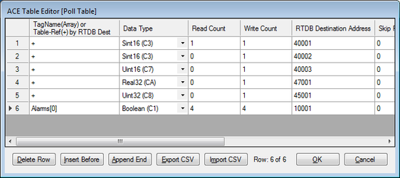
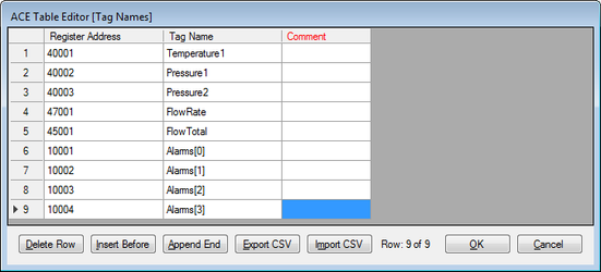
The above example also shows polling a single-dimensional array of Boolean alarms (not a Continuation Poll) and storing the first 4 values into registers 10001-10004. The Master Channel would need to scan Poll Record 6 to request this array.
Example 2: Read Structure using Continuation Poll
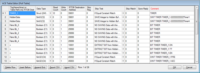
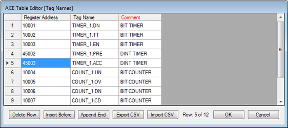
The screen captures below show an example Poll Table and TagNames table for polling a TIMER structure.
The first row includes the tag "TIMER_1", the name of the structure. This is the Poll Record scanned in the Master Channel.
Rows 2 and 3 handle hidden registers (Booleans packed into integers).
Row 4 parses and discards five bits from Timer4, then stores three Booleans from the timer (DN, TT, and EN) into 10001-10003, and two integers (PRE, ACC) into 45002-3.
RTDB
See the RediGate Configuration Manual for information on configuring the RTDB.
The RTDB table should be imported using the L5X Import tool in the ACM Utility. The PLC polling setup can get somewhat complicated, so it is not recommended to modify the table by hand.
Tag Names
See the RediGate Configuration Manual for information on configuring the TagNames object.
The TagNames table should be imported using the L5X Import tool in the ACM Utility. The PLC polling setup can get somewhat complicated, so it is not recommended to modify the table by hand.
See Elecsys ACE Management Utility for more information on using the ACM Utility.