HART to RediGate Master
- Jon Tandy
- Former user (Deleted)
- Former user (Deleted)
Introduction
In this tutorial, we will be demonstrating connectivity to a HART device using an RS-232 HART Modem.
The configuration used in this example polls PV values from any HART device with an address of 0-15 on a HART network. We will use a RediGate 110e to demonstrate this connectivity, but this tutorial can be applied to any RediGate device with an available serial RS-232 port.
This tutorial also goes on to explain how to set up the RediGate to convert HART values to Modbus TCP registers, which would require that your RediGate has an open Ethernet or Cellular connection that can be polled by a Modbus TCP master device.
Pre-Requisites
- A RediGate 100 or 400 series device with an available serial port
- Completion of the Getting Started Guide for your respective RediGate device (RediGate 100 or RediGate 400)
- An RS-232 HART modem (such as ProComSol or Viator)
- A HART device (addressed 0-15) connected to the HART modem
Example 1: Polling HART PV Values with the RediGate
- Confirm that the HART modem is properly connected to the RediGate and your HART network – the leads on the modem should be placed across the 250 ohm resistor of the HART circuit:
- (TANDY TO ADD NETWORK DRAWING HERE)
- Using ACE, open the default config you used in the "Getting Started Guide."
- Download the Elecsys-HART-Demo.zip from the Example Configurations page.
You will need to extract the .xml file from the .zip file you downloaded from the website. By default, ACE stores configuration files in the Documents\Elecsys\ACE\CFG folder, but you can store the configuration in any file location accessible by the ACE program.
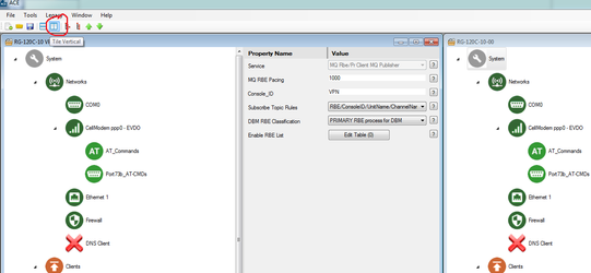
You cannot copy/paste nodes unless both configurations are open within the same instance of ACE. You can use the "Tile" buttons to have the windows automatically size themselves within the ACE program:
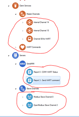
Report 3
- Modbus Slave Channel 0
- OpenModbus Slave Channel 2
Edit your COM2 object to match the serial settings of your HART modem:
Baud Rate: 1200
Parity: Odd
Word Length: 8 Bits
Stop Bits: One
Rx Buffer Size: RS-232
Warm Up Time: 5
Warm Down Time: 5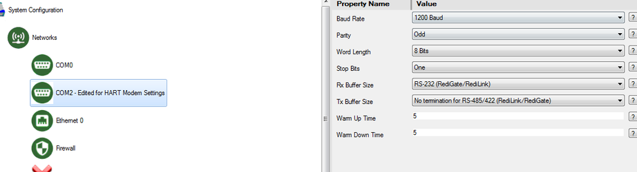
Connect to the RediGate's MMI and check Diagnostics option 9 to determine which HART device(s) are polling successfully:
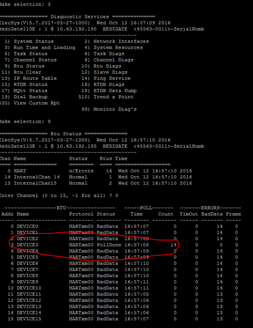
In the above screenshot, the HART device with short address 3 is the only device being polled successfully because it is the only device on the network
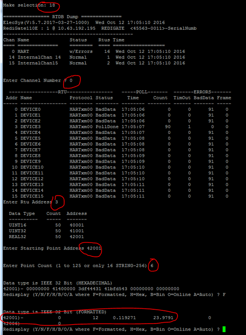
- PV values for each device are stored in RTDB registers 42002-42006, so to view those values, perform an RTDB data dump on the address of the HART device
- Options 3 → 18 → 0 → (address of HART device, in this example it is 3, but that well vary) → 42001 → 6 → F
- Options 3 → 18 → 0 → (address of HART device, in this example it is 3, but that well vary) → 42001 → 6 → F
The values displayed in the RTDB dump should correspond to the PV values in the HART transmitter. For more advanced configuration options, please see the Protocol_HART-Master documentation. To connect your HART data to an IoT platform via MQTT, visit the IIoT Platform Quick Starts page. To setup the RediGate as a Modbus slave device, proceed to "Example 2" below.
Example 2: Polling HART PV's as Modbus Values
The “HART device scanner” configuration includes a network Modbus channel (IP port 3040 for encapsulated Modbus, or port 502 for Open Modbus/TCP). This allows a Modbus host system to read HART data from the RediGate. All Modbus slaves are set to report 32-bit data as pairs of 16-bit registers, but they can be configured to respond with 32-bit registers.
The table below outlines how the RediGate maps the HART values to Modbus slave addresses:
RTDB register | Description | 16-bit Slave register |
40001 | Command register (see below) | 40001 |
40002 | Response register (see below) | 40002 |
40003 | CMD 00 - Expanded device type | 40003 |
40004 | CMD 00 - Min number of preambles, request message | 40004 |
40005 | CMD 00 - HART protocol revision | 40005 |
40006 | CMD 00 - Device revision level | 40006 |
40007 | CMD 00 - Software revision level | 40007 |
40008 | CMD 00 - (MSB 5 bits) Hardware revision level (LSB 3 bits) Physical signalling code | 40008 |
40009 | CMD 00 - Flags | 40009 |
40010 | CMD 00 - Min number of preambles, response message | 40010 |
40011 | CMD 00 - Max number of Device Variables | 40011 |
40012 | CMD 00 - Configuration Change Counter | 40012 |
40013 | CMD 00 - Extended field device status | 40013 |
40014 | CMD 00 - Manufacturer ID code | 40014 |
40015 | CMD 00 - Private label distributor code | 40015 |
40016 | CMD 00 - Device Profile | 40016 |
41001 | CMD 00 - Device ID | 41001 |
41002 | CMD 13 - Tag (3 bytes/4 characters per register) | 41003 |
41003 | CMD 13 - Tag | 41005 |
41004 | CMD 13 - Descriptor (3 bytes/4 characters per register) | 41007 |
41005 | CMD 13 - Descriptor | 41009 |
41006 | CMD 13 - Descriptor | 41011 |
41007 | CMD 13 - Descriptor | 41013 |
42002 | CMD 03 - milliamp | 42003 |
42003 | CMD 03 - PV1 (also CMD 01) | 42005 |
42004 | CMD 03 - PV2 | 42007 |
42005 | CMD 03 - PV3 | 42009 |
42006 | CMD 03 - PV4 | 42011 |
(none) | CMD 38 - Reset configuration change flag | |
(none) | CMD 42 - Master reset (reboot device) |
There are two Modbus slave devices defined in the configuration:
HART device information from one device. Channel 0, device 1 is specified by default. To see device data for a different HART device, modify the configuration for “Modbus NetSlave unit 1”, and/or “OpenModbus Slave unit 1”. Or, add a similar Slave Attach object pointing to a different Channel/RTU and using a different Modbus slave address. See the table under Modbus Map for a list of Modbus registers to use for device values. Note that the data for commands other than CMD00 will only appear in these registers upon request through the Custom Report #3 (see Diagnostics via MMI) or by writing the poll index value to the Command Register.
Communication status values for all HART devices (0=failed, 7=good comms)
30001-30016 Status for COM1, HART devices 0-15
For more information on configuring the RediGate as a Modbus slave, see Modbus TCP Slave Configuration and RediGate Configuration Manual (Modbus Network Slave Channel)