RediGate 100 Hardware Manual
- Jon Tandy
- Former user (Deleted)
- Jon Tandy (Deactivated)
- Former user (Deleted)

Product Information
Full information about other Elecsys products is available on our website at www.elecsyscorp.com and the RediGate Product Support page.
Product Support
Tel: +1-913-890-8905
Fax: +1-913-982-5766
Email: idc-support@elecsyscorp.com
Headquarters, Sales, Support & Manufacturing
Elecsys Corporation
846 N Mart-Way Court
Olathe, KS 66061
Tel: +1-913-647-0158
Fax: +1-913-982-5766
Email: info@elecsyscorp.com
While Elecsys may assist customers with their choice of products, the final choice of product for a specific application is entirely the responsibility of the buyer. Elecsys' entire liability with respect to its products or systems is defined in the Elecsys standard terms and conditions of sale.
Any example code is provided only to illustrate the use of Elecsys products. No warranty, either expressed or implied, is made regarding any example code provided by Elecsys and Elecsys shall incur no liability whatsoever arising from any use made of this code.
Disclaimers
The information in this manual is believed to be accurate at the time of publication. Elecsys Corporation assumes no responsibility for inaccuracies that may be contained in this document and makes no commitment to update or keep current the information contained in this manual. Elecsys Corporation assumes no responsibility for any infringements of patents or other rights of third parties that may result from its use. Elecsys Corporation reserves the right to make changes or improvements to this document and/or product at any time and without notice. While Elecsys may assist customers with their choice of products, the final choice of product for a specific application is entirely the responsibility of the buyer. Elecsys' entire liability with respect to its products or systems is defined in the Elecsys standard terms and conditions of sale.
Any example code is provided only to illustrate the use of Elecsys products. No warranty, either expressed or implied, is made regarding any example code provided by Elecsys and Elecsys shall incur no liability whatsoever arising from any use made of this code.
Electrostatic Discharge (ESD) Protection
These units contain devices that could be damaged by the discharge of static electricity. At all times, please observe industry standard ESD precautions when handling the unit.
![]() WARNING: DO NOT CONNECT OR DISCONNECT CABLES WHEN ENERGIZED, UNLESS POWER HAS BEEN REMOVED FROM THE EQUIPMENT OR THE AREA IS KNOWN TO BE FREE OF IGNITABLE CONCENTRATIONS OF FLAMMABLE SUBSTANCES.
WARNING: DO NOT CONNECT OR DISCONNECT CABLES WHEN ENERGIZED, UNLESS POWER HAS BEEN REMOVED FROM THE EQUIPMENT OR THE AREA IS KNOWN TO BE FREE OF IGNITABLE CONCENTRATIONS OF FLAMMABLE SUBSTANCES.
© 2024 Elecsys Corporation
Table of Contents
Preface
Scope of this Manual
This manual describes the hardware configuration of the Elecsys RediGate 100 series Edge-of-Network Gateway products.
Electromagnetic Compatibility (EMC)
The RediGate is classified as a component with regard to FCC EMC regulations, and it is the user’s responsibility to ensure that systems using the product are compliant with the appropriate EMC standards.
This equipment has been tested and found to comply with the limits for a Class A digital device, pursuant to part 15 of the FCC Rules. These limits are designed to provide reasonable protection against harmful interference when the equipment is operated in a commercial environment. This equipment generates, uses, and can radiate radio frequency energy and, if not installed and used in accordance with the instruction manual, may cause harmful interference to radio communications. Operation of this equipment in a residential area is likely to cause harmful interference in which case the user will be required to correct the interference at his own expense.
See RediGate 100 Hardware Manual#Certifications for a list of certifications of the RediGate products. To ensure compliance with Electromagnetic Emissions Interference (EMI) standards, the user must install a ferrite on the Ethernet cable (see RediGate 100 Hardware Manual#Installing Ferrite Core).
Radio Frequency Requirements
This device complies with Part 15 of FCC Rules. Operation is subject to the following two conditions:
- This device may not cause harmful interference.
- This device must accept any interference received, including interference that may cause undesired operation.
- To comply with RF safety requirements, you must maintain a distance of 20 cm from the antenna when operating the device.
- Each antenna of this device must not be co-located within 20 cm of any other antenna or transmitter. Antenna requirements are listed in Cellular Antenna on page 25.
The RediGate may be supplied with one of the following transmitter modules:
- RG-1x0C-10-00: Telit EVDO cellular module (FCC ID: RI7DE910-DUAL. IC ID: 5131A-DE910DUAL)
- RG-1x0C-21-00 or RG-1x0C-22-00: Telit GSM cellular module (FCC ID: RI7HE910. IC ID: 5131A-HE910)
- RG-1x0C-30-00: uBlox CAT-M1 modem (FCC ID: XPY2AGQN4NNN. IC ID: 8595A-2AGQN4NNN)
- RG-1x0C-40-00: Quectel CAT-M1 modem (FCC ID: XMR201707BG96. IC ID: 10224A-201709BG96)
(Note that some early models of RG-110C-40-00 were built with the uBlox CAT-M1 modem and should be configured accordingly. Serial numbers include: 63263-xxxx, 63833-0001, 63908-0001, 64894-xxxx.)
Changes or modifications to the product not expressly approved by Elecsys Corporation could void the user’s authority to operate the equipment.
Introduction
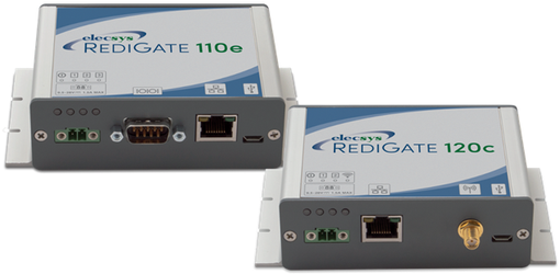
The RediGate is a ruggedized field proven edge-of-network front end processor designed for industrial field applications. This single device enables a seamless migration path for quicker data acquisition, automatic communication failover, cyber security, bandwidth management, and protocol conversion throughout your entire industrial communication network.
With a wide selection of industry standard and legacy protocols, the RediGate can gather data from almost any field device and deliver it to your enterprise data systems. Combining our Advanced Configuration Environment (ACE) with several application programming languages, the RediGate can be easily programmed for most applications.
The RediGate has an optional integrated cellular modem, Ethernet, and/or serial communication ports, depending on the needs of the end user’s application. Utilizing its native MQTT client, the RediGate directly interfaces with messaging middleware/data brokers, new and legacy SCADA hosts, ERP systems, Leak Detection, Maintenance Systems and other enterprise applications. Elecsys also provides a hosted M2M solution for remote monitoring of field equipment, as well as middleware solutions for Modbus or OPC-aware customer SCADA/EMS host systems.
This manual provides information describing the hardware for the Elecsys RediGate products. It details the standard and optional hardware components, technical specifications, and other hardware information that may be needed to configure the device.
The RediGate consists of hardware circuitry mounted in a rugged metal enclosure and running a Linux operating system. RediGate units are shipped fully tested and may be pre-loaded with customer-specific configurations prior to shipment.
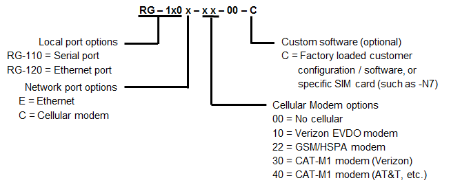
RediGate Model Options
The RediGate 100 Series Gateways have a variety of hardware and software options depending on the model chosen. Please contact Elecsys to obtain pricing for a particular configuration. The table below gives model numbers for several standard part numbers of the RediGate 100 Series. All models include a Micro-USB administrative console port.
Accessory Options
Elecsys provides several accessories for use with the RediGate. Please contact Elecsys to obtain pricing and model numbers for accessory equipment.
RediGate 100 - Included Accessories | |
|---|---|
Power Cable | 6.5 foot cable for connection from RediGate to power source |
DIN Rail Mounting Kit | Kit for mounting enclosure to a standard DIN rail |
DB-9 Screw Terminal Adapter | DB-9 to 10-way screw termination for external wiring to RediGate serial port (P/N 15-0429-09, supplied with RediGate 110E and 110C) |
| Hinged Ferrite Core | 250 ohm ferrite for EMI compliance on Ethernet connections |
See RediGate Product Comparison and Selection Guide for a full list of part numbers, features, and additional accessories.
Specifications
Enclosure / Dimensions
Model | RediGate |
Width | 4.88” (12.40 cm) |
Length | 2.90“ (7.37 cm) (excluding connectors) |
Height | 1.35” (3.43 cm) (excluding DIN rail mount feet) |
Weight | 0.5 lbs (0.23 kg) |
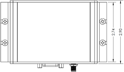
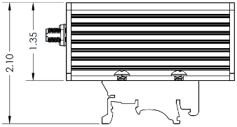
Mounting Dimensions
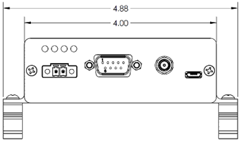
The mechanical and mounting dimensions of the RediGate are shown in the diagrams below (all dimensions in inches).
Top
Bottom
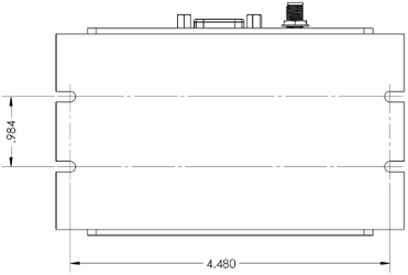
Side
Front (RediGate 110C)
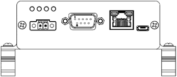
Front (RediGate 110E)
Front (RediGate 120C)
Front (RediGate 120E)
Mounting Instructions
The RediGate is intended to be installed in a Restricted Access Location, defined as a location for equipment where both of the following apply:
- Access can only be gained by service persons or by users who have been instructed about the reasons for the restrictions applied to the location and about any precautions that shall be taken; and
- Access is through the use of a tool or lock and key, or other means of security, and is controlled by the authority responsible for the location.
When mounting the Director, allow sufficient space to connect the cables to the enclosure. There are two recommended means of mounting the device: panel mount, or DIN rail mount.
For panel mounting the RediGate, use four screws of an appropriate size and type to securely attach the device to a customer-supplied panel or enclosure, using the four keyhole slots on the sides of the RediGate, as shown in the dimensional diagrams in the previous section. Connect all the I/O cables, and lastly attach the power connector to the RediGate.
The RediGate is supplied with two (2) optional DIN rail clamps (shown on the bottom view dimensional drawing in the previous section). To mount the RediGate to DIN rail, use the following instructions:
- Determine the correct location and orientation of the RediGate that will accommodate all attached cables and connectors.
- Install a piece of DIN rail (35mm top hat rail) to the mounting location using appropriate screws or bolts. DIN rail should be installed horizontally, and should be a minimum of 5 in. (127mm) in length.
- Using the four supplied DIN rail clamp screws (No. 6, 3/8”), attach the two DIN rail clamps to the keyhole slots on the sides of the RediGate housing (see pictures under Dimensions beginning on page 10).
- Hang the spring side of the RediGate’s DIN rail clamps on the DIN rail and snap into place.
- Ensure that the mounting is secure, then connect all the I/O cables, and lastly attach the power connector to the RediGate.
Compliance with Hazardous Area Standards
The RediGate has approval for installation in Class I Division 2 Groups A, B, C and D Classified Hazardous Locations, temperature class T4. Class, Division, and Group are defined as:
- Class defines the general nature of the hazardous material in the surrounding atmosphere. Class I is for locations where flammable gases or vapors may be present in the air in quantities sufficient to produce explosive or ignitable mixtures.
- Division defines the probability of hazardous material being present in an ignitable concentration in the surrounding atmosphere. Division 1 locations are presumed to be hazardous. Division 2 locations are areas where gas, dust, or vapors can exist under abnormal conditions.
- Group defines the hazardous material in the surrounding atmosphere. Groups A to D are defined as follows:
- Group A – Atmosphere containing acetylene, gases or vapors of equivalent hazards.
- Group B – Atmosphere containing hydrogen, gases, or vapors of equivalent hazards.
- Group C – Atmosphere containing ethylene, gases, or vapors of equivalent hazards.
- Group D – Atmosphere containing propane, gases, or vapors of equivalent hazards.
For the RediGate to be approved for hazardous locations, it must be installed according to the National Electrical Code (NEC) Article 501 (or Canadian Electrical Code, Section 18), and any local code requirements, if applicable.
DO NOT CONNECT OR DISCONNECT CABLES WHEN ENERGIZED, UNLESS POWER HAS BEEN REMOVED FROM THE EQUIPMENT OR THE AREA IS KNOWN TO BE FREE OF IGNITABLE CONCENTRATIONS OF FLAMMABLE SUBSTANCES.
When installing units in a hazardous area, make sure all installation components selected are labeled for use in such areas. Installation and maintenance must be performed only when the area is known to be non-hazardous. Installation or maintenance in a hazardous area could result in personal injury or property damage.
The certificate for this equipment includes the following special conditions for safe use:
- Install the equipment in an IP54 or better enclosure or equivalent location. Any enclosure shall be suitably certified or otherwise approved for Class 1 Division 2 hazardous locations. This may include an instrumentation tray cable (Type ITC) or similar means of limiting access to connect or disconnect cables under hazardous conditions.
- Ensure that the rated input voltage is not exceeded in service.
- The USB ports should not be used in a hazardous location.
System Specifications
General Features:
Feature | Description |
|---|---|
Models | RediGate 110E, 110C, 120E, & 120C |
Memory | RAM: 256MB Flash: 64MB |
Serial Ports | All models: (1) USB serial (user configuration) - configure as COM0 at 115200 baud Models 110E and 110C: (1) RS-232/485/422 - configure as COM2 |
LAN/WAN Ports | Models 110E and 120C: (1) RJ45 10/100baseT Ethernet Model 120E: (2) RJ45 10/100baseT Ethernet See below under Ethernet Ports for eth0/eth1 configuration. |
Cellular | Models 110C and 120C: (1) CAT-M1, EVDO, or GSM/HSPA+ modem - configure as 230.4K baud |
Power
![]() The device is intended to be powered from a Certified Limited Power Source (LPS, as defined in standard 60950-1) or a Certified "Class 2" Power Source (as defined in NEC and CEC).
The device is intended to be powered from a Certified Limited Power Source (LPS, as defined in standard 60950-1) or a Certified "Class 2" Power Source (as defined in NEC and CEC).
![]() WARNING: DO NOT CONNECT OR DISCONNECT CABLES WHEN ENERGIZED, UNLESS POWER HAS BEEN REMOVED FROM THE EQUIPMENT OR THE AREA IS KNOWN TO BE FREE OF IGNITABLE CONCENTRATIONS OF FLAMMABLE SUBSTANCES.
WARNING: DO NOT CONNECT OR DISCONNECT CABLES WHEN ENERGIZED, UNLESS POWER HAS BEEN REMOVED FROM THE EQUIPMENT OR THE AREA IS KNOWN TO BE FREE OF IGNITABLE CONCENTRATIONS OF FLAMMABLE SUBSTANCES.
Connect power to the RediGate using a two-position Phoenix Contact plug (Phoenix part# 1827703 or compatible). The orientation of positive and neutral wires as viewed from the front side of the RediGate is illustrated using the following symbol located on the product overlay:

Feature | Description |
|---|---|
Operational Voltage | +9.5 to +28 V , 1.5 A max. |
Overvoltage Protection | +50 V maximum |
Reverse Voltage Protection | -28 V maximum |
Operating Current @24V | 110 mA nominal |
Power Consumption: * | Nominal Max |
Environmental Characteristics
Feature | Description |
|---|---|
Operating | -40 to +75 °C |
Storage | -40 to +125 °C |
Humidity | 0% to 95% relative humidity (non-condensing) |
Certifications
The EUT was tested for compliance to Directive 2014/30/EU of the European Parliament relating to electromagnetic compatibility using the following harmonized standards.
Feature | Certification | Test Method and Limits |
|---|---|---|
Radiated Emissions | US CFR Title 47, FCC Part 15B EN 61000-6-4:2007/A1:2011 | FCC Part 15.109, Class A ICES-003 Issue 7, Section 6.2 ANSI C63.4:2014, Section 8 EN 61000-6-4:2005/AC:2005 EN 55011:2009/A1:2010 EN 55032:2012/AC:2013 EN ETSI 301 489-1 V2.1.1 AS/NZS 32 VCCI 32 KDB 996369 (Module Integration Verification) |
Conducted Emissions | US CFR Title 47, FCC Part 15B EN 61000-6-4:2007/A1:2011 | FCC Part 15.107, Class A ICES-003 Issue 7, Section 6.1 ANSI C63.4:2014, Section 7 EN 61000-6-4:2005/AC:2005 EN 55011:2009/A1:2010 EN 55032:2012/AC:2013 EN ETSI 301 489-1 V2.1.1 AS/NZS 32 VCCI 32 |
Immunity | EN 61326-1:2013 | Electrostatic Discharge: IEC 61000-4-2:2008; 4 kV/8 kV Contact/Air Radiated Immunity: EFT-I/O lines: IEC 61000-4-4:2004/A1:2010; ±1 kV Surge-DC: IEC 61000-4-5:2014; ±0.5 kV Conducted Immunity – I/O lines: IEC 61000-4-6:2014; 3 Vrms |
| Safety | UL 60950-1:2007 Conforms to IEC/EN 62368-1 | |
| Environmental | RoHS (EU Directive 2011/65/EC) WEEE (EU Directive 2012/19/EU) | |
| Hazardous Location | Class 1, Division 2, Groups A, B, C, and D, temp. T4 Conforms to ISA STD 12.12.01 |
RediGate 100 Hardware
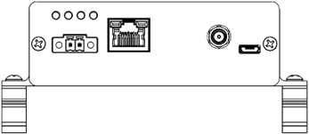
The RediGate is supplied with a rugged metal housing, with hardware options that vary depending on the model and are indicated by symbols located on the product overlay. The front panel of the RediGate contains (in order from left to right):
- Power input connector and status LEDs
- Two Communication Ports (serial, Ethernet, and/or cellular antenna)
- Micro-USB port for administrative console
The following sections describe the operation of the status LEDs and each of the hardware options and connector pinouts.
Status LEDs and Device Ports
There are four status lights that indicate the operational state and communication of the RediGate. The LEDs are located above the power input connector and are indicated with symbols on the product overlay. The normal operation of the Cellular LED is only valid for a RediGate with cellular modem and depends on a correct configuration and an active cellular account and/or SIM card associated with this RediGate.
Symbol | Color | Indicates | Explanation |
| Green | Run | Startup: On solid during initial stage of boot-up, followed by a fast blink until beginning normal operation. Slow blink: Software is in normal operational mode (one blink every 2 seconds). Fast blink: Unit is in process of being reconfigured (2 blinks/second). |
| Amber | Unused | Startup: Turn on after the Run light, then go off when operating system begins to load. Otherwise, these LEDs are unused by the RediGate application. However, they may be controlled by a user application using Linux commands such as: echo 255 > /sys/class/leds/led:1/brightness #turn LED1 on echo 0 > /sys/class/leds/led:2/brightness #turn LED2 off echo timer > /sys/class/leds/led:3/trigger #set LED3 to blink regularly on interval echo 500 > /sys/class/leds/led:3/delay_on #LED3 on-time (ms) echo 500 > /sys/class/leds/led:3/delay_off #LED3 off-time (ms) echo none > /sys/class/leds/led:3/trigger #LED3 non-blinking |
| Red | Unused | (see "Amber" LED description above) |
| Blue | Cellular (110C and 120C only) | Startup: Turns on after LED2, then goes off when operating system begins to load. Solid: Successfully connected to cellular IP network. Solid/Fast blink: Every 3 seconds, fast blink off/on to indicate number of bars of cellular signal strength: 1 bar: -111 to -96 dBm 2 bars: -95 to -81 dBm 3 bars: -80 to -64 dBm 4 bars: -63 dBm or better Off: Not connected to cellular IP network. |


Ethernet Ports
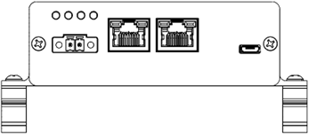
The RediGate 110E and 120C provide one Ethernet port for network communication, and the RediGate 120E provide two Ethernet ports.
![]() WARNING: DO NOT CONNECT OR DISCONNECT CABLES WHEN ENERGIZED, UNLESS POWER HAS BEEN REMOVED FROM THE EQUIPMENT OR THE AREA IS KNOWN TO BE FREE OF IGNITABLE CONCENTRATIONS OF FLAMMABLE SUBSTANCES.
WARNING: DO NOT CONNECT OR DISCONNECT CABLES WHEN ENERGIZED, UNLESS POWER HAS BEEN REMOVED FROM THE EQUIPMENT OR THE AREA IS KNOWN TO BE FREE OF IGNITABLE CONCENTRATIONS OF FLAMMABLE SUBSTANCES.
![]() Ethernet ports do not provide Power over Ethernet (PoE) and should not be connected to an unregulated PoE device.
Ethernet ports do not provide Power over Ethernet (PoE) and should not be connected to an unregulated PoE device.
![]() Ethernet ports not suitable for direct connection to WAN unless an appropriate interface is provided, to ensure lightning surge protection.
Ethernet ports not suitable for direct connection to WAN unless an appropriate interface is provided, to ensure lightning surge protection.
Ethernet ports are 10/100 Mbps and are configured via the ACE program for either a fixed IP address or dynamically assigned DHCP addressing. The ports should be configured to operate on different, non-overlapping IP addresses/subnets. Ethernet ports are identified with the icon:
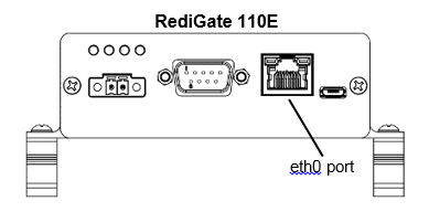
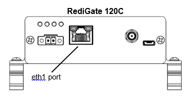
On all RediGate models, the Ethernet port located toward the right of the faceplate (on the 110E, or the rightmost port of the 120E) is identified as ‘eth0’. The port located next to the power connector (on the 120C, or the leftmost port of the 120E) is identified as ‘eth1’. This is important to note when configuring the RediGate in the ACE program, as the Instance Number of the Ethernet objects in ACE must match the numeric value of the actual Ethernet port. The identifications of the ports are shown in the pictures below.

Installing Ferrite Core
To ensure compliance with Electromagnetic Emissions Interference (EMI) standards, the user must install the ferrite on the Ethernet cable during installation (see picture).
The ferrite is supplied with all models of the RediGate with Ethernet ports. It is a 250 ohm, 100 MHz ferrite, Laird model 28A2029-0A2 or similar. | 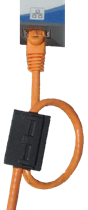 |
USB Configuration Port
The RediGate provides a Micro-USB port on the front for configuration with the ACE program or for local diagnostics using a serial terminal program (such as HyperTerminal, PuTTY, or Tera Term). A USB to Micro-USB cable should be connected from a computer to the USB port on the RediGate, which is marked on the label with the icon:

USB port COM0
You must configure the Micro-USB port as COM0 in the ACE program, using port settings of 115,200 baud, no parity, 8 bits, 1 stop bit. These are the default settings for Linux startup messages. There must also be a SerialMMI object using COM0 under Servers.
Device Serial Port
The RediGate 110E and 110C provide one DB-9 serial port for the local device communication. The port is software-configurable using the ACE program as either RS-232, RS-485, or RS-422 (in the ACE AsyncPort object, set the “Rx Buffer Size” option to ‘232’, ‘485’ for 2-wire RS-485 operation, or ‘422’ for 4-wire RS-485/422 operation). The location of the serial port is indicated on the RediGate label with the serial icon:

Serial port COM2
You must configure the DB-9 (RS-232 or RS-485) port as COM2 in the ACE program, using port settings appropriate for your application.
![]() WARNING: DO NOT CONNECT OR DISCONNECT CABLES WHEN ENERGIZED, UNLESS POWER HAS BEEN REMOVED FROM THE EQUIPMENT OR THE AREA IS KNOWN TO BE FREE OF IGNITABLE CONCENTRATIONS OF FLAMMABLE SUBSTANCES.
WARNING: DO NOT CONNECT OR DISCONNECT CABLES WHEN ENERGIZED, UNLESS POWER HAS BEEN REMOVED FROM THE EQUIPMENT OR THE AREA IS KNOWN TO BE FREE OF IGNITABLE CONCENTRATIONS OF FLAMMABLE SUBSTANCES.
RS-232 Serial Interface
The direction of data with respect to the RediGate serial interface (COM2) is such that the RediGate acts as a DTE (Data Terminal Equipment) device. The pin-out of the DB-9 serial interface in RS-232 mode is as follows:

Pin | RS-232 Name | Type | Description |
|---|---|---|---|
1 | DCD | Input | Data Carrier Detect |
2 | RXD | Input | Receive data |
3 | TXD | Output | Transmit data |
4 | DTR | Output | Data Terminal Ready |
5 | GND | Common | Ground |
6 | DSR | Input | Data Set Ready |
7 | RTS | Output | Request To Send |
8 | CTS | Input | Clear To Send |
9 | RI | Input | Ring Indicate |
When configuring the RS-232 ports using the ACE program, the Flow Control setting allows for hardware flow control (“RTS/CTS” setting), which may be required to control sending and/or receiving data through certain external devices, such as modems. If hardware flow control is not required, set the Flow Control to None (use ‘-1’ for both Warm-up Time and Warm-down Time).
RS-485/RS-422 Serial Interface
RS-485/422 uses an optically isolated, balanced differential system, in which the voltage produced by the driver appears across a pair of signal lines that transmit a single signal. A balanced line driver produces a voltage from 2 to 6 volts across its positive and negative output terminals. A balanced differential line receiver senses the voltage state of the transmission line across the two signal input lines. Up to 32 RS-485 devices or 10 RS-422 devices can be connected together in a multi-drop configuration.
The pin-out of the DB-9 serial interface (COM2) in RS-485 and RS-422 modes is identified as follows (all pins not listed are unused):
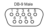
4-wire Pinout:
Pin | 4-wire RS-485/ RS-422 Name | Type | Description |
|---|---|---|---|
1 | TX- | Output | Transmit Data - |
2 | TX+ | Output | Transmit Data + |
3 | RX+ | Input | Receive Data + |
4 | RX- | Input | Receive Data - |
5 | GND | Common | Ground |
2-wire Pinout:
Pin | 2-wire RS-485 Name | Type | Description |
|---|---|---|---|
1 | Data- | Input/Output | Transmit/Receive Data - |
2 | Data+ | Input/Output | Transmit/Receive Data + |
5 | GND | Common | Ground |
When using RS-485 or RS-422 communication modes, set the AsyncPort object to have a value of ‘1’ for both the “Warm-up Time” and “Warm-down Time” properties in ACE. Set the “Tx Buffer Size” property to ‘0’ for no termination resistor, or to ‘1’ for a built-in 120 ohm termination. See the following section for more information on when to use the termination resistor.
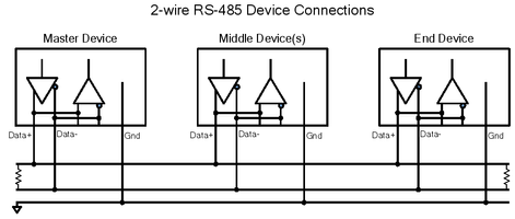
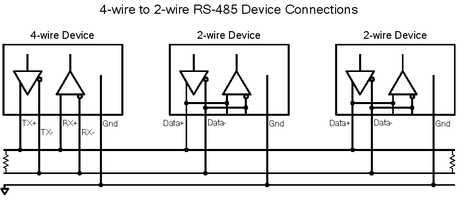
RS-485/422 Wiring Diagrams
The RS-422 interface provides full-duplex communication. It supports one transmitter and up to 10 receivers.
The RS-485 interface can provide either half-duplex or full-duplex communication. The interface supports up to 32 transmitters and receivers on a single network. Only one transmitter should be switched on at a time.
RS-485 and RS-422 generally use a 120W terminating register on both ends of the connection to match the cable impedance of a long transmission line. The installer should confirm that the termination resistors match the rated impedance of the serial cable. When connecting RS-485 or RS-422 devices in a multi-drop configuration, the termination resistor should be used for the devices located at both ends of the network, but not on devices located in the middle.
In RS-485 or RS-422 systems, the ground connection is typically required to properly establish the voltage reference for the differential voltages of the transmit and receive lines. The maximum end-to-end cable length for an RS-485/422 network is rated at 1200 m (4000 ft.). Care should be taken in long runs to use twisted, shielded pair wiring to avoid the introduction of electromagnetic noise on the communication lines.
The serial ground (pin 5) is not isolated from the power supply and antenna ground. If isolation from field equipment is required, an external serial port isolation device would be required.
Multi-drop networks are designed to be wired in a daisy-chain arrangement as shown, rather than a star arrangement (multiple nodes connected to a single point). Typical RS-485 and RS-422 connections are shown in the following figures.

Cellular Modem
The RediGate 110C and 120C provide a modem for cellular network communications. Only one modem may be used, depending on the chosen type of wireless technology. The modem is factory installed in the RediGate, and an SMA jack allows connection to an external cellular antenna. The Host cellular port is indicated on the RediGate label with the icon:

The CAT-M1 modem is based on the Quectel BG96 or uBlox SARA-R410 wireless module and provides LTE/CAT-M1 wireless support. The BG96 modem is certified for use on the AT&T cellular network in the United States and other international networks. The SARA-R410 modem is certified for use on the Verizon network.
The GSM/HSPA modem is based on the Telit HE910 wireless module and provides multi-band GSM/GPRS/EDGE/UMTS/HSPA+ wireless support. The modem is certified for use on the AT&T cellular network in the United States, and the Telus cellular network in Canada.
The EVDO modem is based on the Telit DE910-DUAL wireless module and provides dual band 1xRTT/CDMA/EVDO wireless support. The modem is certified for use on the Verizon cellular network.
The choice of modem may depend on the quality or availability of cellular service at the intended location for device installation.
Cellular Baud Rate
You must configure the CellModem in the ACE program with a rate of no more than 230.4K baud (CellModem instance 0, netppp0).
Cellular Account Activation
In order to use the RediGate with a cellular modem, each device must be included on an active data plan with the cellular carrier. If the application requires inbound (mobile-terminated) connections to the RediGate, it may be necessary to have a public, static IP address. For enhanced security, it may be desired rather to activate cellular service on a private network (APN/VPN) with static IP addresses.
Cellular Antenna
The RediGate with cellular modem requires an external cellular antenna. The antenna should be chosen with the correct frequency band, connector, cable length, and appropriate mounting type.
In the United States, the antenna should support the frequency bands listed below. In other countries, check to make sure what frequencies are used in order to select the correct antenna.
The cellular connector requires an antenna with a standard male SMA plug and 50 ohm cable, with a minimum cable length of 20 cm. FCC requirements in the United States require a maximum gain (including cable loss) as follows:
Frequency | EVDO | GSM | CAT-M1 | CAT-M1 |
746-787 MHz (700 MHz band) | n/a | n/a | 3.67 dBi | 4.0 dBi |
824-846 MHz (850 MHz band) | 5.12 dBi | 5.22 dBi | 4.10 dBi | 4.0 dBi |
1712-1752 MHz (1700 MHz band) | n/a | 3.31 dBi | 6.74 dBi | |
1851-1907 MHz (1900 MHz band) | 6.12 dBi | 6.45 dBi | 7.12 dBi | 4.0 dBi |

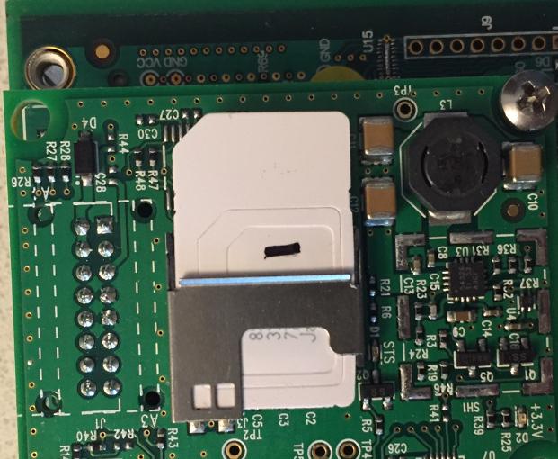
Installing SIM Card
For CAT-M1 and GSM models, the RediGate 100 series products use standard (also known as "mini") SIM cards. The steps below show how to install the SIM card:
- Remove power and all connectors from the front panel. Remove the two mounting screws from either side of the front faceplate
- Gently slide the board out of its enclosure to expose the SIM card slot
- Fully insert the SIM card into the SIM card slot, with the metal contacts facing down and the angled edge facing out
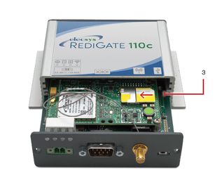
- Gently slide the board back into its housing and carefully replace the two mounting screws to avoid over-tightening. Replace all front panel connectors.
- Example of AT&T's IoT Sim card installed in a RediGate (note the three embedded SIM sizes: Mini, Micro, and Nano):