RediGate P2P Configuration Guide - Point to Point using MQTT
- Former user (Deleted)
- Jon Tandy
- Former user (Deleted)
Introduction
In this tutorial, we will be demonstrating the ability of the RediGate to subscribe to topics published by another RediGate in JSON data format, and serve that data up to a Modbus TCP host. The second part of the example will show command data going from the Modbus host to the field RediGate.
This tutorial uses two RediGates with Internet connectivity to the AWS IoT service. (You could use a similar configuration to a generic MQTT broker, but note that because of MQTT topic restrictions, there may be additional requirements to make the Peer-to-peer application work properly on some platforms, such as IBM or Azure IoT.)
In this example, the two sites are called "Remote Data Publisher" and "Local Data Concentrator" for identification purposes only.
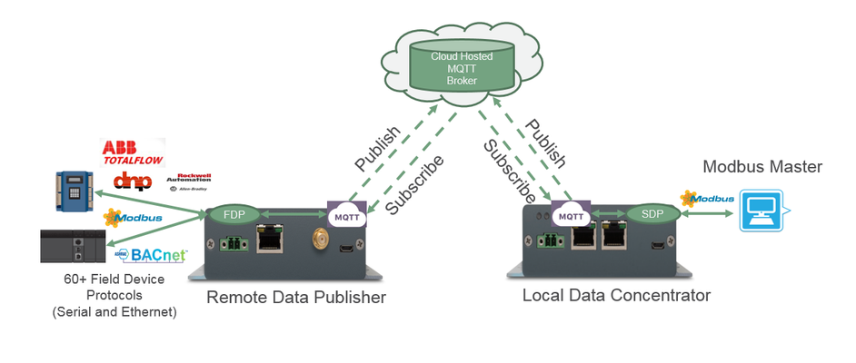
This example illustrates the ability of the RediGate to serve as a cellular replacement for two sites using point-to-point radios for communication. With some adaptation, it may also be used for sharing data in a point-to-multipoint arrangement.
Pre-Requisites
- Two RediGate 100 or 400 series device with internet connectivity
- Completion of the Getting Started Guide and RediGate to AWS IoT for your respective RediGate device (RediGate 100 Series or RediGate 400 Series)
- AWS account with the AWS IoT service enabled (https://aws.amazon.com/iot/)
Setting Up Field RediGate
- Set up a RediGate demo to AWS using this tutorial: RediGate to AWS IoT.
For the System → Unit Name, use "P2P-Field1".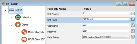
- Save the configuration as P2P-Field1.xml.
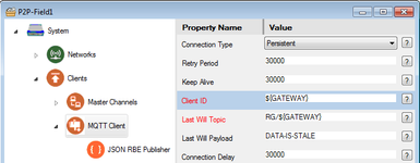
- Make sure the MQTT Client → Client ID is: ${GATEWAY}
- In the JSON RBE Publisher object, edit the Topic Rules table.
Click the "Append End" button to add a third row, and set up the topic rules as follows:
Device Publish:RG/${GATEWAY}/${CHAN}_${DEV}/RBE
Device Subscription:RG/P2P-Concentrator/${CHAN}_${DEV}/CMD
Gateway Subscription:RG/P2P-Concentrator/SYS_SystemFlush/CMD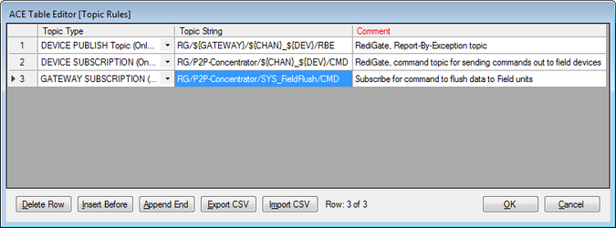
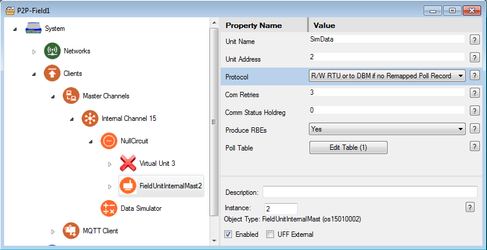
- In the FieldUnitInternalMast2, verify that the "Protocol" selection is set to "R/W RTU or to DBM if no Remapped Poll Record."
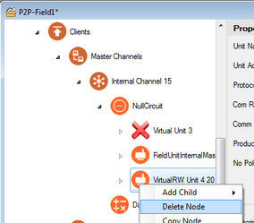
- Right-click on VirtualRW Unit 4, and select Delete Node to delete this object from the original AWS demo.
- Save changes to the P2P-Field1 configuration and upload it to the first RediGate.
Setting Up Concentrator RediGate
- Set up a second RediGate demo to AWS using this tutorial: RediGate to AWS IoT.
For the System → Unit Name, use "P2P-Concentrator".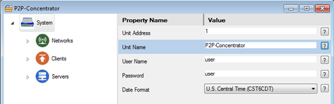
- Save the configuration as P2P-Concentrator.xml.
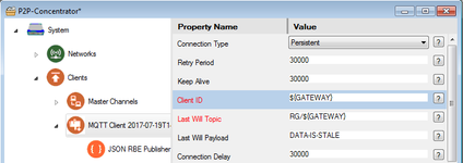
- Make sure the MQTT Client → Client ID is: ${GATEWAY}
- In the JSON RBE Publisher object, edit the Topic Rules table.
Set up the topic rules as follows:
Device Publish (change RBE to CMD):RG/${GATEWAY}/${CHAN}_${DEV}/CMD(Comment: Publish commands to the field RediGate.)
Device Subscription (change CMD to RBE, and ${GATEWAY} to +):RG/+/${CHAN}_${DEV}/RBE(Comment: Subscribe to the publish topic of the field RediGate.)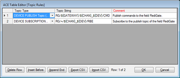
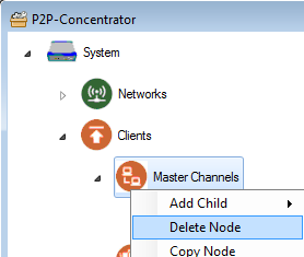
- Right-click on Master Channels and select Delete Node to delete the Master Channels object from the original AWS demo.
- Download Elecsys-P2P-Demo-Concentrator.xml from Example Configurations (RediGate P2P - Point to Point using MQTT example)
- You will need to extract the Elecsys-P2P-Demo-Concentrator.xml file from the .zip file you downloaded from the website. By default, ACE stores configuration files in the Documents\Elecsys\ACE\CFG folder, but you can store the configuration in any file location accessible by the ACE program.
You cannot copy/paste nodes unless both configurations are open within the same instance of ACE. You can use the "Tile" buttons to have the windows automatically size themselves within the ACE program:
- Copy and paste the following objects from the Elecsys-P2P-Demo-Concentrator.xml config into your P2P-Concentrator.xml configuration:
- Master Channels (paste under Clients)
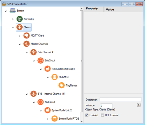
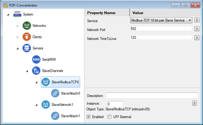
- SlaveModbus TCP0 and SlaveNetwork1 (paste under Slave Channels).
- Master Channels (paste under Clients)
- Under Networks, select Firewall, then click the Edit Table button for Port Management.
Click the Append End button twice, and modify the last two rows to have Dest Port 502 and 3040.
(Should also have INPUT Chain, tcp packets, and ACCEPT Packet.)
Interface name should be the same as your AWS configuration, eth0 or eth1 for Ethernet or ppp0 for cellular.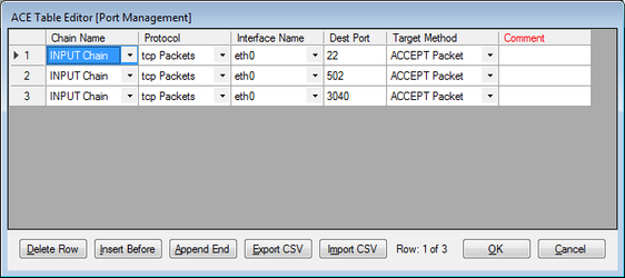
This Firewall setting is necessary to allow the Modbus host to have access for polling the RediGate over a network interface. - Save changes to the P2P-Concentrator configuration and upload it to the second RediGate.
Example 1: Testing P2P Communication
- After loading configurations to both RediGates, test that you are seeing MQTT subscriptions.
From the Main Menu, select 3 (Diagnostic Services), and 17 (MQTT Status).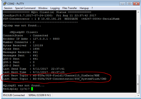
Set up your Modbus host to poll the "P2P-Concentrator" RediGate using the IP address configured in your device, on the interface that you opened in the Firewall (above).
Modbus Versions
NOTE: There are different implementations of TCP/IP Modbus protocol among vendors. You need to be aware of these differences in order to properly set up a Modbus polling network.
For instance:
- Open Modbus/TCP typically uses port 502. It's Modbus format is slightly different from standard Binary Modbus.
- Binary Modbus over TCP/IP doesn't have a defined port. This example configuration uses port 3040.
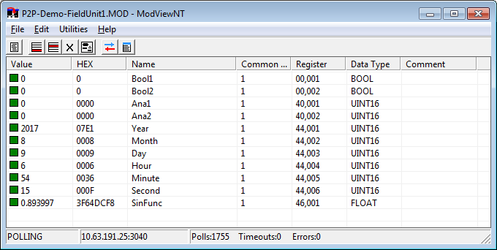
- Either port 502 or 3040 may be used in this RediGate example—the same data is available on both ports.
- The data used in this example includes 44001-44006 (six 16-bit integers) and 46001-46002 (one 32-bit float, little-endian).- Poll the "P2P-Concentrator RediGate using a Modbus TCP client. You should see the data being generated by the "P2P-Field1" RediGate.
Example 2: Sending Commands from Modbus Concentrator to Field
To send commands, the Modbus client must write to digital Coils or analog Holding Registers. The RediGates on both ends must be configured to publish and subscribe for command data, as well as report-by-exception (RBE) data from the field.
- The P2P-Concentrator configuration is already configured to send commands for 10 coils (1-10) and 10 holding registers (40001-40010, 16-bit integer). However, these registers do not have tag names associated with them, so you need to make sure the JSON RBE Publisher → RBE Processing property is set to "No, All RTDB Regs processed for RBE". Otherwise, you would need to add tag names both on the P2P-Concentrator and the P2P-Field1 for the Modbus registers.
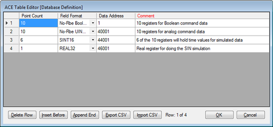
- The P2P-Field1 configuration is already configured to subscribe for commands, but it needs some added registers to store data.
In the RtdbMod → Database Definition, edit the table to insert two rows:- 10 registers, No-Rbe Boolean, starting Data Address 1
- 10 registers, No-Rbe UINT16, starting Data Address 40001
- Use the Modbus host to write a TRUE to Modbus address 1.
Write a non-zero value to Modbus address 40001.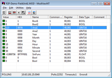
- Verify in the P2P-Field1 RediGate that the values were received.
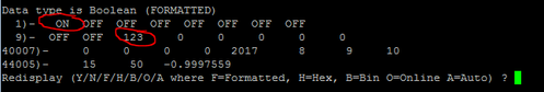
(see Accessing RTDB Data Dump to learn how to view current values)
Complete
Congratulations! You can successfully send data between two point-to-point RediGates. Check out our "Field Device Quick Starts" on the Example Configurations page for examples showing how to connect the RediGate to 60+ industrial protocols.