Automated Processing
- Jon Tandy
- Former user (Deleted)
- Jon Tandy (Deactivated)
Table of Contents
Introduction
The Automated Processing section of the RediGate configuration is a collection of processes designed primarily to collect data from various sources (RTDB, text files) and format them into a "report" which may be published via MQTT, HTTP, and/or stored to the gateway for later retrieval. Specifically, this allows the automation of data collection from various types of flow computers, such as Omni, Spirit, AutoPilot Pro, Control Microsystems, TotalFlow, or others. The Automated Processing section also includes miscellaneous features such as device time sync, PLC heartbeat, and other forms of script-driven logic which don't require ISaGRAF or POD programming.
Automated Processing Placeholder

The Automated Processing placeholder is the parent of all the other Process, Report, and Proc-Script definitions,
| Attributes | Function |
|---|---|
| Object Type | Automated_Processing |
| Parent(s) | System → Clients |
| Instance | Must be 0 |
Processes

The Processes object is the parent of all individual Process objects and contains a few general properties of the Automated Processing function.
There are many different types of child Process objects. Many contain device-specific functionality, such as methods for reading and writing Modbus registers to obtain an hourly or batch ticket from an Omni or AutoPilot Pro flow meter. Other Process types include more generic functionality for handing any sort of data based on customer-defined trigger conditions, such as the Generic Registers or Proc-User-Logic objects.
Each Process object includes a Data Process Table with 18 columns and one or more rows. Each row in each Data Process Table represents a specific set of "process" logic and in most cases results in a Report being generated. Although the details vary among the different process types, all of them are configured to reference a certain Master Channel number and Field Unit address.
For processes using an RTDB report type, a certain "trigger" condition may be used to indicate when to obtain data from the RTDB registers in that Field Unit and stored into the output report. For processes using a File report type, the data is obtained from a text file in the file system and either stored into RTDB registers or into the output report. In either case, the output report may be published by some means such as MQTT or stored locally. The output process may be just to call a script, which can perform other logic instead. Then, the next Process is examined for its "trigger" condition, and so on.
| Attributes | Function |
|---|---|
| Object Type | Processes |
| Parent(s) | System → Clients → Automated_Processing |
| Instance | Must be 0 |
| Properties | Values |
|---|---|
| Report Pacing | Delay (in milliseconds) each cycle through check the Process objects, and additionally a delay whenever a Process generates a published Report. The Report Pacing is intended to limit the pace of the Automated Processing, so as to limit consumption of system resources and to allow time for a report to be sent via MQTT before creating the next Report. |
| Report Directory | Location of output Report files to be generated. Default option is "RAM Drive" (/tmp/director). |
| Group ID | Configurable text field, which may be included in an MQTT topic for a Report using the ${GROUP} wildcard variable (see Report Name property of the Process-RTDB-Report or Process-FILE-Report objects). Group ID serves a similar function as the MQ-RBE "Console ID" or Sparkplug "Group Name" properties, to allow an MQTT topic level grouping of RediGate sites. |
| Spare | Spare property. |
| Reserved | Reserved for internal use. |
Generic Registers Process

The Generic-Registers process object can be used to pull any sort of data registers out of the RTDB, or data elements from a text file, and assemble them into a Report file. It does not include any custom program logic for specialized functions or flow computer models (as with Time-Syncs, Omni-Modbus-Archives, etc.). It simply operates on a trigger condition (time, register value, etc.) to generate the Report.
| Attributes | Function |
|---|---|
| Object Type | Generic-Registers |
| Parent(s) | System → Clients → Automated_Processing → Processes |
| Instance | 0 |
Every row in the Process table points to a Report definition that creates an output Report file. Therefore, the Reports section and at least one Report definition must be defined before the Data Process Table can be configured.
| Data Process Table | Values |
|---|---|
| Channel | Master Channel used for process logic and obtaining RTDB data. |
| RTU | Field Unit address used for process logic and obtaining RTDB data. |
| Type | For the Generic-Registers process, the options include:
|
| CommStatReg | RTDB register address containing the first of 5 Field Unit communication status registers (register should contain 7=good, 0=bad comms). If the communication status is checked and found to be in a failed state, the processing on this row will be skipped. Following the convention of the Field Unit's Comm Status Holdreg, use a 40,xxx register to point to the communication status register in the System Status RTU, or use a 30,xxx register to point to the communication status register in the Field Unit's own RTDB. Set CommStatReg to 0 to check protocol status of the Master Channel's protocol driver instead of a Comm Status Holdreg register. Set CommStatReg to -1 to ignore the communication status. Process logic for this row will occur regardless of comms status. |
| Report | Select one Report definition to define the structure of the output data report produced by this process row. |
| DataRegs | If this row uses a Process-RTDB-Report or Process-PBuf-Report type: If DataRegs is non-zero, that RTDB register in Channel/RTU is used as the "base register" for Report generation. The Report defines offsets from DataRegs. This option may be used when more than one block of similar data is stored in the RTDB; thus, the same Report can be reused by setting DataRegs to the starting register of each block of registers. (For example: Field Units 1 and 2 each have analogous blocks of data at 40001-40020 and 40101-40120. Four rows could be defined in Generic Registers with different RTU address (1 and 2) and DataRegs column (starting address 40001 and 40101), and Report defined with data elements at Offset 0 through 19; the same Report would be called four different times using data from different units and different blocks of data). If DataRegs is zero, the Report must be defined using actual register addresses in the RTDB. This option might be used, for example, if a set of numbered addresses with similar data is used in multiple Channel/RTU/RTDB. The registers do not have to be in a contiguous block of addresses. (For example: Field Units 1 through 10 each have an analogous data at 10001-5 and 40001-40020. Ten rows could be defined in Generic Registers with different RTU addresses, DataRegs set to 0, and the Report defined with data elements at fixed register locations 10001-10005 and 40001-40020; the same Report would be called ten different times using data from different units). If this row uses a Process-FILE-Report type: DataRegs should be the RTDB register of a STRING type value, where the Tag Name of the register must be defined as the name of the text file containing data to process. The directory "/tmp/director/" is added to the beginning of the Tag Name, plus a suffix "_CC_RRRRR" is automatically appended to the Tag Name (where CC is the Channel and RRRRR is RTU/Field Unit address configured on this row, each with leading zeros as needed). The contents of the specified DataRegs RTDB register is unused. For instance, assume there is a text file containing ASCII data, stored with the filename of |
| TrigMode | The TrigMode option selects a method for triggering the Report generation. See below for more information on the TrigMode options. For instance, the Report generation logic could be triggered based on timing (day, minute, or hour), on a register value matching a certain condition, or any change in the value of any register in a block of registers. |
| TrigReg | RTDB address in Channel/RTU containing some value to trigger on. See below for a discussion on the TrigMode options. |
| TrigValue | Constant value to use for trigger comparison, or RTDB register containing a value for "Compare Register" TrigMode. See below for a discussion on the TrigMode options. |
| TrigAdjust | If a Report generation logic is "triggered," the trigger value in the TrigReg can be modified based on the TrigAdjust option (e.g., to prevent the Report from being immediately triggered again). TrigAdjust options are:
|
| TrigWrap | If the TrigAdjust "INCREMENT" option is used, TrigWrap tells at what point the value should roll over to its low ("WrapTo") value. If TrigWrap is greater than 20000, it is used as a register point to a maximum "Increment" value. If less than 20001, it is a constant value. For instance, if TrigWrap is set to 40001, and the value in 40001 is 30000, then if the TrigReg register will be incremented to 30000, then after the next Report trigger, it will be set to the value in Parm1. |
| Run | The Run value is unused in processing, but it can be used as part of the Report filename (MQTT topic) using the ${RUN#} variable. |
| Parm1 | If the TrigAdjust "INCREMENT" option is used, Parm1 contains the "WrapTo" value. Once the value rolls over at its maximum limit, it will be set to the constant integer contained in Parm1. For instance, this may be used to set the minimum roll-over value to 1 instead of 0, if a particular trigger value requires it. |
| COUNT DataRegs | (This is the "Parm2" parameter.) If the TrigMode "CRC" option is used, this value determines the number of sequential registers starting at DataRegs that will be calculated for the CRC, to determine if any of the registers has changed. See below for a discussion on the TrigMode options. |
| Inhibit Reg | Unused |
| Inhibit Test | Unused |
| Proc-Logic | Unused |
| Comment | Optional column, allowing a descriptive comment to be entered for each row in the table. The Comment field is unused in the configuration. |
TrigMode Options for Generic Process
The TrigMode option determines what condition is monitored for this row in the Generic process table in order to generate a Report. Options include:
- REGISTER Compare modes
Compare the value in register address configured in TrigReg with a value in a register address configured in TrigValue. Trigger a report if the two values compare according to the TrigMode condition.
- TrigReg |= ("NotEqual to") TrigValue REGISTER
- TrigReg == ("Equal to") TrigValue REGISTER
- TrigReg >= ("Greater than or equal to") TrigValue REGISTER
- TrigReg <= ("Less than or equal to") TrigValue REGISTER - CONSTANT Compare modes
Compare the value in register address configured in TrigReg with the constant integer value configured in TrigValue. Trigger a report if the two values compare according to the TrigMode condition.
- TrigReg |= ("NotEqual to") TrigValue CONSTANT
- TrigReg == ("Equal to") TrigValue CONSTANT
- TrigReg >= ("Greater than or equal to") TrigValue CONSTANT
- TrigReg <= ("Less than or equal to") TrigValue CONSTANT - ANY CHANGE in 16-bits TrigReg
ANY CHANGE in 32-bits TrigReg modes
Trigger a report if the value in register address configured in TrigReg (lower 16 bits or lower 32 bits) changes from the previous sample. This could be used, for instance, to trigger on a Timestamp value created by the Poll Table upon receiving new data/RBE. (TrigValue is unused.) - Not Used (trigger every cycle)
Report is triggered every time the Automated Processing cycles through this row in the Generic process table, limited only by the CommStatReg register and processing cycle time. Note that this should be used cautiously if the Report defines an MQTT publish process, because it would result in a large amount of MQTT data traffic. - Timed reporting (MINUTES, HOURS, or DAYS of TrigValue Interval)
TrigValue column contains a constant integer number of minutes, hours, or days. Report is triggered on this fixed interval. (TrigReg is unused.) - COMPARE CRC32 of 'COUNT DataRegs' (Save CRC to TrigReg)
On every sample of the Process row, calculate a 16-bit CRC of the data registers starting at DataRegs, using Count of DataRegs (Parm2) as the number of sequential registers; then calculate a second CRC-16 of the same data registers in reverse order. Concatenate these two CRC values into a 32-bit value and store the result into the register configured in TrigReg (must be a UINT32 RTDB register in Channel/RTU). If the calculated 32-bit CRC value changes from the previous CRC value, trigger Report generation. (TrigValue is unused.) This can be used to check a range of registers for a report-by-exception type trigger.
TrigAdjust Options for Generic Process
Most of the TrigAdjust options determine how (or if) to modify the value in the register configured in TrigReg when a Report is triggered. Note: these options typically only make sense when using the TrigMode options of REGISTER Compare or CONSTANT Compare. For instance, compare a value to be greater than zero and trigger the Report, until the value is decremented down to zero.
- NONE
No modification of the TrigReg register. - REMOTE INCREMENT, REMOTE DECREMENT, REMOTE ZERO
When Report is generated, write a value to the field device via its Poll Table, using the Channel/RTU/TrigReg address. The value to be written is either the existing TrigReg value incremented or decremented by 1, or a zero (0). When using REMOTE DECREMENT, the value decreases down to zero and remains there (no wrapping).
Additional options:
TrigWrap contains the maximum value for the REMOTE INCREMENT option. If TrigWrap is set to a number >20000, it points to an RTDB register that contains the maximum value; otherwise, the TrigWrap column itself is the (constant) maximum value.
Parm1 contains the constant "WrapTo" value for the REMOTE INCREMENT option. After the value increments positively past the maximum value, it will be set to Parm1.
TrigWrap and Parm1 columns are unused for REMOTE DECREMENT or ZERO options.
For both INCREMENT and DECREMENT options, the TrigReg register value is set directly in the RTDB, in addition to writing the value to the remote device. - RTDB INCREMENT, RTDB DECREMENT, RTDB ZERO
When Report is generated, write a value to the RTDB register configured in Channel/RTU/TrigReg (not sent to the remote device). The value to be written is either the existing TrigReg value incremented or decremented by 1, or a zero (0). When using REMOTE DECREMENT, the value decreases down to zero and remains there (no wrapping).
Additional options:
TrigWrap contains the maximum value for the REMOTE INCREMENT option. If TrigWrap is set to a number >20000, it points to an RTDB register that contains the maximum value; otherwise, the TrigWrap column itself is the (constant) maximum value.
Parm1 contains the constant "WrapTo" value for the REMOTE INCREMENT option. After the value increments positively past the maximum value, it will be set to Parm1.
TrigWrap and Parm1 columns are unused for REMOTE DECREMENT or ZERO options.
Read-ProtoBuff-Payload Process
The Read-ProtoBuff-Payload process object is used for parsing Google Protobuf-formatted payload messages, typically received through an MQTT subscription.
To publish a Google Protobuf payload, see the Generic-Registers process object instead.
Attributes | Function |
|---|---|
| Object Type | Read-ProtoBuff-Payload |
| Parent(s) | System → Clients → Automated_Processing → Processes |
| Instance | 0 |
Every row in the Process table points to a Report definition that describes a received Protobuf message. Therefore, the Reports section and at least one Report definition must be defined before the Data Process Table can be configured.
Data Process Table | Values |
|---|---|
| Channel | Master Channel used for storing RTDB data. |
| RTU | Field Unit address used for storing RTDB data. |
| Type | For the Generic-Registers process, the options include:
|
| CommStatReg | RTDB register address containing the first of 5 Field Unit communication status registers (register should contain 7=good, 0=bad comms). If the communication status is checked and found to be in a failed state, the processing on this row will be skipped. Following the convention of the Field Unit's Comm Status Holdreg, use a 40,xxx register to point to the communication status register in the System Status RTU, or use a 30,xxx register to point to the communication status register in the Field Unit's own RTDB. Set CommStatReg to 0 to check protocol status of the Master Channel's protocol driver instead of a Comm Status Holdreg register. Set CommStatReg to -1 to ignore the communication status. Process logic for this row will occur regardless of comms status. |
| Report | Select one Report definition to define the structure expected from the subscribed data for this process row. |
| DataRegs | If DataRegs is non-zero, that RTDB register in Channel/RTU is used as the "base register" for Report generation. The Report defines offsets from DataRegs. This option may be used when more than one block of similar data is stored in the RTDB; thus, the same Report can be reused by setting DataRegs to the starting register of each block of registers. (For example: Field Units 1 and 2 each have analogous blocks of data at 40001-40020 and 40101-40120. Four rows could be defined in Read-ProtoBuff-Payload with different RTU address (1 and 2) and DataRegs column (starting address 40001 and 40101), and Report defined with data elements at Offset 0 through 19; the same Report would be called four different times using data from different units and different blocks of data). If DataRegs is zero, the Report must be defined using actual register addresses in the RTDB. This option might be used, for example, if a set of numbered addresses with similar data is used in multiple Channel/RTU/RTDB. The registers do not have to be in a contiguous block of addresses. (For example: Field Units 1 through 10 each have an analogous data at 10001-5 and 40001-40020. Ten rows could be defined in Read-ProtoBuff-Payload with different RTU addresses, DataRegs set to 0, and the Report defined with data elements at fixed register locations 10001-10005 and 40001-40020; the same Report would be called ten different times using data from different units). |
| TrigMode | The TrigMode option selects a method to use in response to a receiving and parsing a Protobuf payload message. If either of the "WRITE" options are selected, it can be used by another process to indicate that we have received a message, and perhaps to take some further action. TrigMode options are:
|
| TrigReg | RTDB address in Channel/RTU to write a trigger value, indicating a received message, if configured by TrigMode. |
| TrigValue | If TrigMode selects a trigger action, this should either be a constant value to write, or an RTDB register address containing a value to write. |
| TrigAdjust | Unused |
| TrigWrap | Unused |
| Run | Unused |
| Parm1 | Unused |
| Parm2 | Unused |
| Inhibit Reg | Unused |
| Inhibit Test | Unused |
| Proc-Logic | Unused |
| Comment | Optional column, allowing a descriptive comment to be entered for each row in the table. The Comment field is unused in the configuration. |
Device TimeSync Process
The Time-Syncs process object uses special program logic to synchronize the clock in either an Omni Modbus-compatible flow computer or an Allen Bradley PLC.
| Attributes | Function |
|---|---|
| Object Type | Time-Syncs |
| Parent(s) | System → Clients → Automated_Processing → Processes |
| Instance | 0 |
Every row in the Process table handles the time synchronization for one field device. The Time-Syncs process is an exception, in that it does not require a Report object to be defined.
| Data Process Table | Values |
|---|---|
| Channel | Master Channel of the Omni or Allen Bradley device. |
| RTU | Field Unit address useof the Omni or Allen Bradley device. |
| Type | For the Time-Syncs process, the options include:
|
| CommStatReg | RTDB register address containing the first of 5 Field Unit communication status registers (register should contain 7=good, 0=bad comms). If the communication status is checked and found to be in a failed state, the processing on this row will be skipped. Following the convention of the Field Unit's Comm Status Holdreg, use a 40,xxx register to point to the communication status register in the System Status RTU, or use a 30,xxx register to point to the communication status register in the Field Unit's own RTDB. Set CommStatReg to 0 to check protocol status of the Master Channel's protocol driver instead of a Comm Status Holdreg register. Set CommStatReg to -1 to ignore the communication status. Process logic for this row will occur regardless of comms status. |
| Report | Unused |
| DataRegs | Starting register in the RTDB for the device timestamp registers polled from the Omni or Allen Bradley device. In the Allen Bradley, some custom programming is required to place the timestamp into six consecutive registers (Year, Month, Day, Hour, Minute, Second), and a seventh register is written to by the RediGate, which the PLC must take the new timestamp and store into the PLC's clock. For the Omni, the RediGate will read the standard six timestamp registers (Omni registers 3867-3872: Hour, Minute, Second, Month, Day, Year). |
| TrigMode | Unused |
| TrigReg | RTDB address in Channel/RTU containing a trigger to synchronize the time whenever the TrigReg register is non-zero. This can be used, for instance, to read the "Power Fail" flag (Omni register 1829). |
| TrigValue | Constant value to write to the device after the time has been synchronized. The value is written via the RTDB register (and Poll Table) specified in the TrigWrap column. This can be used, for instance, to write to the "Reset Power Failed" flag (Omni register 1713). |
| TrigAdjust | Unused |
| TrigWrap | RTDB register to write the TrigValue after the time has been synchronized (sent to the device via the Poll Table). |
| Hour | (This is the "Run" parameter.) Optional parameter, can be used to automatically write the timestamp to the device once/day at a certain Hour and Minute. |
| Minute | (This is the "Parm1" parameter.) Optional parameter, can be used to automatically write the timestamp to the device once/day at a certain Hour and Minute. |
| Parm2 | Unused |
| Inhibit Reg | Unused |
| Inhibit Test | Unused |
| Proc-Logic | Unused |
| Comment | Optional column, allowing a descriptive comment to be entered for each row in the table. The Comment field is unused in the configuration. |
Heartbeat Monitor Process
The Heart-Beat-Monitor process object uses special program logic to send an MQTT death certificate based on the loss of an incrementing "heartbeat" value that is read from a PLC (NOTE: this process currently only works with the MQTT Client, not MQTT Extra Client, JSON-RBE, or Sparkplug). This feature requires custom logic in the PLC to generate a value that periodically increases, which is read by the Poll Table into the RTDB. The value is presumed to stop increasing if the PLC is taken out of "run" mode or if the logic locks up for some reason.
If the heartbeat value stays dead for a period of time, the RediGate will continually send death certificates whenever the process is triggered. During this time, the normal MQ-RBE data messages will be prevented. When the heartbeat comes back to normal, MQ-RBE data communication returns to normal.
The Heart-Beat-Monitor process is not needed to send a death certificate on loss of communication to a device, because in that case the MQTT publisher will automatically send a death certificate. It is only used to send a death certificate on a device that still communicates but is presumed to have locked in a non-running state.
| Attributes | Function |
|---|---|
| Object Type | Heart-Beat-Monitor |
| Parent(s) | System → Clients → Automated_Processing → Processes |
| Instance | 0 |
Every row in the Process table handles the heartbeat monitoring for one field device. The Heart-Beat-Monitor process is an exception, in that it does not require a Report object to be defined.
| Data Process Table | Values |
|---|---|
| Channel | Master Channel used for the PLC. |
| RTU | Field Unit address used for the PLC. |
| Type | For the Heart-Beat-Monitor process, the options include:
|
| CommStatReg | RTDB register address containing the first of 5 Field Unit communication status registers (register should contain 7=good, 0=bad comms). If the communication status is checked and found to be in a failed state, the processing on this row will be skipped. Following the convention of the Field Unit's Comm Status Holdreg, use a 40,xxx register to point to the communication status register in the System Status RTU, or use a 30,xxx register to point to the communication status register in the Field Unit's own RTDB. Set CommStatReg to 0 to check protocol status of the Master Channel's protocol driver instead of a Comm Status Holdreg register. Set CommStatReg to -1 to ignore the communication status. Process logic for this row will occur regardless of comms status. |
| Report | Unused |
| DataRegs | Unused |
| TrigMode | Unused |
| TrigReg | RTDB address in Channel/RTU containing the heartbeat value polled from the PLC. |
| TrigValue | Constant number of seconds, after which an unchanging heartbeat value will trigger the fail condition and send MQTT death certificate. |
| TrigAdjust | Unused |
| TrigWrap | Unused |
| Run | Unused |
| Parm1 | Unused |
| Parm2 | Unused |
| Inhibit Reg | Unused |
| Inhibit Test | Unused |
| Proc-Logic | Unused |
| Comment | Optional column, allowing a descriptive comment to be entered for each row in the table. The Comment field is unused in the configuration. |
Omni Modbus Archives Process
The Omni-Modbus-Archives process object uses special program logic to handle batch/ticket archive data polled from an Omni flow computer using Modbus register-based polling. In addition to the specialized logic in the Omni-Modbus-Archives function, other ACE configuration objects must be included in the configuration for the Modbus Master Channel, Poll Table, and SOS Table, which are integral to the acquisition of Omni archive data.
Background: The Omni flow computer (or an Omni-compatible device) uses various Modbus registers for data acquisition. The archive records themselves are contained in Omni "pseudo-registers," Archive 701 through 712 (Modicon-compatible registers 40702 through 40713), which are not a normal, single-value register, but a request for a certain type of meter data that returns a "record." Each record is a block of data of a certain size, which is typically configurable for individual customer needs. What is ordinarily the "Count" of registers in a normal Modbus request instead must contain a "record pointer" to the particular record of data in the archive. Because of the highly customized variation of the Modbus protocol used by Omni, the RediGate must use special logic to control/modify the record pointer for each archive request.
There are three registers in the Omni used for each batch/ticket archive, which contain the Max Record, Current Record, and Requested Record values (Omni registers 3701-3736, or Modicon-compatible registers 43702-43737). These values need to be polled regularly from the Omni for each archive type in order to know when a new record is available. The Omni-Modbus-Archives process logic checks these values, and when a record is available (Current ≠ Requested), it will request a new register from the Omni. The process logic is described in more detail below.
| Attributes | Function |
|---|---|
| Object Type | Omni-Modbus-Archives |
| Parent(s) | System → Clients → Automated_Processing → Processes |
| Instance | 0 |
Every row in the Process table points to a Report definition that creates an output Report file. Therefore, the Reports section and at least one Report definition must be defined before the Data Process Table can be configured.
| Data Process Table | Values |
|---|---|
| Channel | Master Channel of the Omni Modbus unit used for process logic and obtaining RTDB data. |
| RTU | Field Unit address of the Omni Modbus unit used for process logic and obtaining RTDB data. |
| Type | For the Omni-Modbus-Archives process, the options include:
|
| CommStatReg | RTDB register address containing the first of 5 Field Unit communication status registers (register should contain 7=good, 0=bad comms). If the communication status is checked and found to be in a failed state, the processing on this row will be skipped. Following the convention of the Field Unit's Comm Status Holdreg, use a 40,xxx register to point to the communication status register in the System Status RTU, or use a 30,xxx register to point to the communication status register in the Field Unit's own RTDB. Set CommStatReg to 0 to check protocol status of the Master Channel's protocol driver instead of a Comm Status Holdreg register. Set CommStatReg to -1 to ignore the communication status. Process logic for this row will occur regardless of comms status. |
| Report | Select one Report definition to define the structure of the output data report produced by this process row. Because the Omni-Modbus-Archives process deals with Modbus register-based polling, the Report must be a Process-RTDB-Report type. |
| DataRegs | If DataRegs is non-zero, that RTDB register in Channel/RTU is used as the "base register" for Report generation. The Report defines offsets from DataRegs. For the Omni-Modbus-Archives process, this will generally be the block of data containing the latest archive record. This option may be used when more than one block of similar data is stored in the RTDB; thus, the same Report can be reused by setting DataRegs to the starting register of each block of registers. (e.g., Field Units 1 and 2 each have an analogous block of data at 40001-40020 and 40101-40120. If more than one archive is obtained, multiple rows can be defined in this table for the same RTU address, and rows for each Modbus flow computer, with each row calling one or more Report definitions. If DataRegs is zero, the Report must be defined using actual register addresses in the RTDB. |
| TrigMode | Unused |
| TrigReg | RTDB address in Channel/RTU containing the first of three registers containing the Max, Current, and Requested Record for the archive. |
| TrigValue | Unused |
| TrigAdjust | Unused |
| TrigWrap | Unused |
| Run | The Run value is unused in processing, but it can be used as part of the Report filename (MQTT topic) using the ${RUN#} variable to identify the run number if the flow meter contains archives for multiple flow. |
| SOS-Enable | (This is the "Parm1" parameter.) This must be set to the RTDB register used in the SOS table that enables and disables the poll for the actual archive data record. The processing logic will set this register to True (or 1) to enable the archive poll, and set it to False (or 0) once the record has been received. |
| Parm2 | Unused |
| Inhibit Reg | Unused |
| Inhibit Test | Unused |
| Proc-Logic | Unused |
| Comment | Optional column, allowing a descriptive comment to be entered for each row in the table. The Comment field is unused in the configuration. |
Omni-Modbus-Archives Configuration and Logic
Setup of a configuration for Omni Modbus archive retrieval requires several components. These will not be documented in full here, but see the RediGate Configuration Manual for general details on the ACE object settings.
Modbus Poll Table
Each Omni must be configured under a Master Channel, asynch or network serial Circuit, a Modbus FieldUnit with Poll Table, and an RTDB containing enough registers to hold the data. Below are a few typical Modbus polls that might be configured:
| Source Register | Source Format | Count | Destination Register | Comment |
|---|---|---|---|---|
| 3701 | OFFSET 16bit Hreg | 36 | 40001 | 12 sets of Max, Current, and Requested Record |
| 701 | OFFSET 16bit Hreg | 119 | 20001 | Station batch archive (16-bit registers) - count of 119 should match the number of actual registers configured in the Omni for this archive. |
| 702 | OFFSET 16bit Hreg | 110 | 20201 | Station hourly archive (16-bit registers) - count of 110 should match the number of actual registers configured in the Omni for this archive. |
All the above polls might be scanned every 60 seconds, for instance, in the Master Channel's Scan Table. But the polls for Archive 701, 702, etc., will be skipped most of the time because of the SOS Table. Note that the above registers are shown in Omni-compatible (non-Modicon) format – if using Modicon compatible addressing, add 40001 (use registers such as 43702, 40702, 40703, etc.), and use the standard 16-bit or other non-OFFSET source formats.
Modbus SOS Table
Each of the above batch/hourly archive record polls need two entries in the SOSMod table, such as:
| Poll Index | Trig. Addrs. | Trig. Value | TX Start Byte | TX #Bytes Filled | Fill from Addrs. | Fill Control | Extra Logic | RTDB for Poll Length | Comment |
|---|---|---|---|---|---|---|---|---|---|
| 2 | 10001 | 0 | 7 | 2 | 0 | Skip Poll if Matching Trigger | None | 0 | If 10001=False, skip poll. Poll Record 2 refers to the 2nd Poll Table entry, above. |
| 2 | 10001 | 1 | 7 | 2 | 40100 | No Conversion (LSB first) | None | 0 | If 10001=True, send poll. Register 40100 can be any register, value doesn't matter. |
Each set of SOS entries needs to use a unique trigger address (e.g., 10001, 10002).
Omni-Modbus-Archives Process Table
In the Omni-Modbus-Archives process object, one entry would be needed for every meter run for every Omni-compatible meter in the RediGate.
| Channel | RTU | Type | CommStatReg | Report | DataRegs | TrigReg | SOS-Enable | Comment |
|---|---|---|---|---|---|---|---|---|
| * | * | OMNI Modbus Archive | * | * | 20001 | 40001 | 10001 | Publish archive data report for data starting at 20001. |
| * | * | OMNI Modbus Archive | * | * | 20201 | 40004 | 10002 | Publish for second archive starting at 20201, with second set of record data at 40004 and SOS flag at 10002. |
* Channel, RTU, CommStatReg, and Report should be set according to the Omni device and Report definition in the configuration.
Process Logic
The Omni archive processing as described above will go through the following steps:
- Scan Table polls the sets of three registers (Max, Current, Requested) regularly. The first meter run data registers are stored into 40001-40003.
- When 40002 (Current) is not equal to 40003 (last Requested record), the logic will increment the value in 40003 and write the new Requested Record to the Omni, in sequential order.
- Once 40003 is read back from the Omni and confirmed to match what was written, the logic will set the SOS-Enable register to True.
- On the next Scan Table cycle, this will cause the SOS Table to activate the poll for the archive at register 701. Data will be returned into registers starting at 20001.
- The logic will check that the first six registers starting at DataRegs (20001) is different from previous, indicating a new timestamp and other data. Once the data is received, the SOS-Enable register 10001 will be set to False.
- Then the Report will be generated from the DataRegs registers according to the Report definition. If the Report is defined to be published via MQTT, it will be transmitted.
Omni Command 65 Archive File Process
The Omni-Cmd65-File process object uses special program logic to handle a raw ASCII text file report polled from an Omni flow computer using Modbus command 65, using an SOS table to control when the report is retrieved. In addition to the specialized logic in the Omni-Cmd65-File process, other ACE configuration objects must be included in the configuration for the Modbus Master Channel, Poll Table, and SOS Table, which are integral to the acquisition of Omni file data.
Background: The Omni device contains report definitions which are normally used to produce a human-readable printout. The Command 65 driver in the Modbus FieldUnit polls this ASCII report in small chunks until the entire text report has been obtained and saves it into the Linux filesystem. Then a register value indicates that the report is available, and the file processing can begin to parse the raw ASCII report from the flow meter, create a new formatted report, and publish it via MQTT. Processing of the raw ASCII text file report is generally handled by searching for particular whitespace-separated fields using the Process-File-Report. Every row in the Process table links to a formatted Process-File-Report definition and creates a unique Report output. Process logic is described in more detail below.
| Attributes | Function |
|---|---|
| Object Type | Omni-Cmd65-File |
| Parent(s) | System → Clients → Automated_Processing → Processes |
| Instance | 0 |
Every row in the Process table points to a Report definition that creates an output Report file. Therefore, the Reports section and at least one Report definition must be defined before the Data Process Table can be configured.
| Data Process Table | Values |
|---|---|
| Channel | Master Channel of the Omni Modbus unit used for process logic and obtaining CMD 65 file data. |
| RTU | Field Unit address of the Omni Modbus unit used for process logic and obtaining CMD 65 file data. |
| Type | For the Generic Registers process, the options include:
|
| CommStatReg | RTDB register address containing the first of 5 Field Unit communication status registers (register should contain 7=good, 0=bad comms). If the communication status is checked and found to be in a failed state, the processing on this row will be skipped. Following the convention of the Field Unit's Comm Status Holdreg, use a 40,xxx register to point to the communication status register in the System Status RTU, or use a 30,xxx register to point to the communication status register in the Field Unit's own RTDB. Set CommStatReg to 0 to check protocol status of the Master Channel's protocol driver instead of a Comm Status Holdreg register. Set CommStatReg to -1 to ignore the communication status. Process logic for this row will occur regardless of comms status. |
| Report | Select one Report definition to define the structure of the output data report produced by this process row. Because the Omni-Cmd65-File process deals with ASCII text files, the Report must be a Process-FILE-Report type. |
| FileNameReg | (This is the "DataRegs" parameter.) The FileNameReg should typically be a STRING type register in the RTDB, which is used by the Poll Table to specify the name of the file created by the Modbus CMD 65 data acquisition of the raw ASCII report. The Tag Name of this register identifies the filename; the retrieved file to be processed will be stored in /tmp/director/ with a filename of TagName_CC_RRRRR, where "TagName is the tag of the FileNameReg, "CC" is the Master Channel number and RRRRR is the Modbus unit ID (the Omni CMD 65 poll automatically appends these numbers with the underscores). |
| TrigMode | Unused |
| TrigReg | RTDB address in Channel/RTU containing data to trigger when the raw ASCII text file has been acquired and is ready to be processed.
|
| TrigValue | RTDB register containing CRC-32 of the raw ASCII file, stored by the Modbus Poll Table (CMD 65) after completing the read. Used by Omni-Cmd65-File process to determine when the report is available for processing – after CRC-32 changes, process and publish the Report. |
| TrigAdjust | Unused |
| ACK Register | (This is the "TrigWrap" parameter.)
|
| HistRecord | (This is the "Run" parameter.) RTDB register for writing the "Count HistRecords" parameter, below, used to request a count of historical archives for certain types of Cmd65 reports (Alarm, Audit). Otherwise, the HistRecord parameter is unused, other than optional use in an MQTT topic using the "${RUN}" variable. |
| SOS-Enable | (This is the "Parm1" parameter.) This must be set to the RTDB register used in the SOS table that enables and disables the poll for the actual archive data record. The processing logic will set this register to True (or 1) to enable the archive poll, and set it to False (or 0) once the record has been received. |
| Count HistRecords | (This is the "Parm2" parameter.) This is the count of historical records needed in the request for certain types of historical archives. This is the value written into HistRecord, above. |
| Inhibit Reg | This is a Boolean register in the RTDB which is used for certain types of historical archives (Snapshot, Status, Product, Alarm, Measurement Audit, System Audit, Initialization), to prevent more than one archive request from operating at the same time. Each of these report processes uses Omni register 16303 as the Report Command register, so the Omni-Cmd65-File process will set the Inhibit Reg while one archive file is being retrieved and clear the register when finished, so other processes can acquire their own archive. |
| Inhibit Test | Unused |
| Proc-Logic | Unused |
| Comment | Optional column, allowing a descriptive comment to be entered for each row in the table. The Comment field is unused in the configuration. |
Omni-Cmd65-File Configuration and Logic
Setup of a configuration for Omni Command 65 archive retrieval requires several components. These will not be documented in full here, but see the RediGate Configuration Manual for general details on the ACE object settings. This example shows retrieval of a Batch Historical Report from an Omni 7000. Others (Snapshot, Alarm, Audit, Omni 6000, etc.) are not shown.
Modbus Poll Table
Each Omni must be configured under a Master Channel, asynch or network serial Circuit, a Modbus FieldUnit with Poll Table, and an RTDB containing enough registers to hold the data. Below are a few typical Modbus polls that might be configured:
| Source Register | Source Format | Count | Destination Register | Comment |
|---|---|---|---|---|
| 51889 | OFFSET 32 Bit B/B Endian | 22 | 51889 | Status of record retrieval (51889), Request ID (51901), Newest record ID (51909), etc. These register addresses are given in Omni-compatible mode (non-Modicon), hence the OFFSET Source Format. |
| 49102 | Omni7K Cmd-65 | 60001 | 25001 | 49102=Omni register 9101 + 40001 offset. The "Count" is not actually a count, but register 60001 should be configured with a Tag name of the ASCII text file, which will be saved after retrieval from the Omni (/tmp/director/TagName_CC_RRRRR), where /tmp/director/ is hard coded, and _CC and _RRRRR are the channel and RTU address). The CRC-32 of the ASCII file will be stored in register 25001 (UINT32) after finishing retrieval. |
The above polls might be scanned every 60 seconds, for instance, in the Master Channel's Scan Table. But the poll for 49102 will be skipped most of the time because of the SOS Table.
Modbus SOS Table
The Omni Cmd-65 archive record polls need an entry in the SOSMod table, such as:
| Poll Index | Trig. Addrs. | Trig. Value | TX Start Byte | TX #Bytes Filled | Fill from Addrs. | Fill Control | Extra Logic | RTDB for Poll Length | Comment |
|---|---|---|---|---|---|---|---|---|---|
| 2 | 10001 | 0 | 7 | 2 | 0 | Skip Poll if Matching Trigger | None | 0 | If 10001=False, skip poll. Poll Record 2 refers to the 2nd Poll Table entry, above. |
Each set of SOS entries needs to use a unique trigger address (e.g., 10001, 10002).
Omni-Cmd65-File Process Table
In the Omni-Cmd65-File process object, one entry would be needed for every meter run for every Omni-compatible meter in the RediGate that uses Command 65.
| Channel | RTU | Type | CommStatReg | Report | FileNameReg | TrigReg | TrigValue | ACK Register | SOS-Enable | Comment |
|---|---|---|---|---|---|---|---|---|---|---|
| * | * | OMNI-7K Batch | * | * | 60001 | 51901 | 25001 | 51889 | 10001 | Parse and publish archive data report for file named in Tag of register 60001. |
* Channel, RTU, CommStatReg, and Report should be set according to the Omni device and Report definition in the configuration.
Process Logic
The Omni Command 65 archive processing as described above will go through the following steps:
Check 51909 (TrigReg+8) for newest record ID. When 51901≠51909, write request ID to 51901. Set register 10001 to trigger SOS table read of Cmd65. for Publish archive data report for data starting at 20001.
- Scan Table polls registers starting at 51889 (Record status, Request ID, Newest record) regularly.
- When 51909 (Current, in TrigReg+8) is not equal to 51901 (last Requested record, in TrigReg), the logic will increment the value in TrigReg and write the new Request ID to the Omni, in sequential order.
- Once 51889 (ACK Register) is read back from the Omni and becomes 0 (report ready), the logic will set the SOS-Enable register to True.
- On the next Scan Table cycle, this will cause the SOS Table to activate the poll for the archive using Command 65. Data will be polled in blocks of 128 bytes until completion and stored into a file pointed to by the Tag name of register 60001. The CRC-32 of the file will be stored in 25001 (Destination Register in Poll Table, TrigValue in process table).
- The logic will check that the register in TrigReg (25001) is different from previous, indicating a new file has been obtained. The SOS-Enable register 10001 will be set to False.
- Then the Report will be generated from the contents of the file (via filename in register 60001) according to the Report definition. If the Report is defined to be published via MQTT, it will be transmitted.
Reports Placeholder

The Reports placeholder is the parent object of all individual Report objects.
| Attributes | Function |
|---|---|
| Object Type | Reports |
| Parent(s) | System → Clients → Automated_Processing |
| Instance | Must be 0 |
Process Report (RTDB, FILE, and PBuf types)
At least one Report must be created before the Process types can be configured, because the "Report" column in most of the Process object tables is taken dynamically from the list of Process-Report objects.
There are three Process-xxxx-Report types under the Reports placeholder:
 | The Process-RTDB-Report object takes data from RTDB registers and stores them into a Report output file in a defined output format for MQTT publishing. It may also be used to read and scale RTDB data, and store the scaled values back into RTDB registers. |
 | The Process-FILE-Report object takes data from a text file in the filesystem and stores them into a Report output file in a defined output format for MQTT publishing, and/or store the values into RTDB registers. |
| The Process-PBuf-Report object takes data from RTDB registers and creates a Google Protobuf payload for MQTT publishing, or receives a subscribed Google Protobuf payload from MQTT and parses into RTDB registers. It may also be used to read and scale RTDB data, and store the scaled values back into RTDB registers. |
The main object properties are similar for each type of reports. When the Automated Process row (Generic, Omni, etc.) triggers the Report to operate for a given Channel and RTU address (FieldUnit), the Report generally gathers information and either creates a publishable report or stores data to the RTDB, or both. Then once the Report has been created, if a publisher process or script is defined to operate, that process will be called.
| Attributes | Function |
|---|---|
| Object Type | Process-RTDB-Report object |
| Parent(s) | System → Clients → Automated_Processing → Reports |
| Instance | Must be between 0 and 999 |
Note, it is possible to define an empty Report with no rows; for example, if the Report is being called by a Process for the sole purpose of running a Process Script.
| Properties | Values |
|---|---|
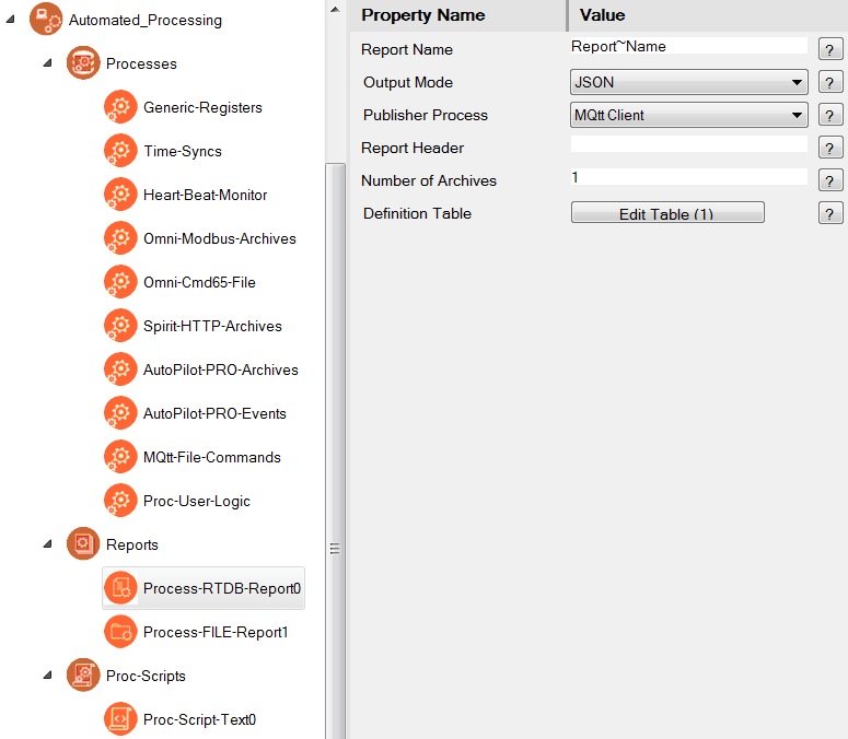
| Report Name | The Report Name is used for a dual purpose. It defines a file to be created in the filesystem into which the contents of the Report data is saved. All report files are saved to the Report Directory location defined in the Processes object (such as /tmp/director/Reports or /tmp/sdcard1/Reports). The name of the report is also used as the MQTT topic name when publishing the report via one of the MQTT processes. Any single tilde (~) in the Report Name will be converted to a slash (/) in the MQTT topic name. If the Report Name begins with "${TIME}~~", the filename up to the double tildes will be removed before converting the filename to an MQTT topic. The Report Name may use wildcard variables, which will be substituted when the Report is created. See Report Name Wildcards. below. Example: When a ProcessScript publish action is selected, the Report Name is passed to the Bash script as the first command line parameter, which may be used by the Bash script to identify the name of the Report to be acted on. |
| Output Mode | The Output Mode defines the structure of data to be saved into the Report. The report may be a Binary structure or a text format (CSV, JSON, XML, TXT, etc.). See Report Output Modes, below, for a description of the different Report types. |
| Publisher Process | Select the action to take once the Report has been created. MQTT processes will publish the Report file, using the filename as the topic. ProcessScript options will run a script after creating the Report, with the script located in /usr/director/bin/ProcessScript0.blnk (or similar). To create these scripts, use the Proc-Script-Text or Bash Script object – the script must be named "ProcessScript0" (ending with a digit 0 through 9). Options are:
|
| Report Header | For most Report types, the Report Header field is not used. For XML reports, the Report Header is used as the first line of the XML file between "<? ?>" tags. When using the ProcessScript publisher process, the Report Name is passed to the Bash script as the first command line parameter, followed by the Report Header as one or more additional command line parameters. This may be used to pass some defined variables or other parameters into the script. |
| Number of Archives | Number of Report files of a particular name, channel, and RTU to retain in the filesystem. This option is only currently used when the Report Name begins with "${TIME}" (variable filename), in order to limit the number of retained archive files. All of the other Report Name Wildcard options result in a fixed Report Name, which is overwritten each time. |
| Definition Table | See the sections below for definition of different types of Report tables. Process-RTDB-Report |
Report Name Wildcards
The Report Name property Report object may include wildcard variables. Any variables shown with one or more "#" symbols indicate that an integer number will be substituted for the variable, with the minimum number of digits specified, using leading zeros where needed according to the number of "#" characters.
Be careful when naming the report, to make sure that multiple reports created by different Process objects yield unique filenames/MQTT topics, if it matters to your application.
| Wildcard variable | Description |
|---|---|
| ${TIME} | Insert the current time and date into the Report filename when it is created. Time is created in the form: YYYYMMddTHHmmss.Z000 (such as "20190703T150233.Z000"). This will result in multiple Report files, with the quantity of stored files limited to the Number of Archives. Typically, the ${TIME} should be followed by two tildes (~~), so that when the file is published, the filename will be converted to an MQTT topic that excludes the time and date and the two tildes. |
| ${GATE} | Unit Name property of the gateway, taken from the System object. |
${GATE#} | Unit Address property of the gateway, taken from the System object, such as "241" |
| ${RTU} | Unit Name of the Channel/RTU defined in the Process row that called this report. |
| ${RTU#} | Unit Address of the Channel/RTU defined in the Process row that called this report (with leading zeros, if more than one "#"). |
| ${CHAN} | Channel Name of the Channel/RTU defined in the Process row that called this report. |
| ${CHAN#} | Channel Number of the Channel/RTU defined in the Process row that called this report (with leading zeros, if more than one "#"). |
| ${ETH0} | IP address of the eth0 (Ethernet instance 0) object, with 3 digits per octet, such as "011.022.033.044". At present, only the eth0 address is supported as a variable. |
| ${SERIAL} | Unit serial number of the gateway device. |
| ${RUN#} | Value from the Run column in the Process row that called this report (with leading zeros, if more than one "#"). |
${PARM1#} | Value from the Parm1 or Parm2 column in the Process row that called this report (with leading zeros, if more than one "#"). |
Report Output Modes
The Output Mode property of the Process Report object defines the overall structure of the report being generated. Generally speaking, each row in the Report's Definition Table creates one data element in the Report file that is created. Below is a description of the different Output Mode options:
| Output Mode | Description |
|---|---|
| Binary (no tag names) | Store data into a binary (hex) data format, byte for byte, using the Output Format of each row in the Report Definition Table to determine the number of bytes used for each element. Nesting and Array structures and Label elements in the Report are not supported. The Report Header property and Units column are unused. |
XML (Attributes Only) XML (Values and Attributes) | Store data as XML format, where every row in the report adds a sequential XML parameter with a "<field>" element name. The Report Header property creates a starting XML tag inside "<? ?>" characters. Variable name and any defined Units are stored as attributes of the <field> element. "XML (as Attributes Only)" stores the value with a "Value=" attribute inside the XML tag. "XML (Values and Attributes)" stores the value in between the <field> </field> tags. Nesting creates an XML section with the element name ("<name> </name>") from the Name column in the NESTING START row of the Report. (The NESTING END must use the same Name column value as its matching NESTING START row.) Arrays create an XML "<array> </array>" element. In the two examples below, the Report Definition includes several data fields, an array called "1st Array", and a Nesting section called "1stObject". Example (Attributes Only):
Example (Values and Attributes):
|
| JSON | Store data as JSON format, where every row in the report adds a tag/value pair in the JSON structure. Nesting creates a JSON object "Name:{ }", where the Name comes from the Name column in NESTING START row of the Report. Arrays create a JSON array "Name:[ ]" structure, where the Name comes from the Name column in the ARRAY START row of the Report. Elements between ARRAY START and ARRAY END are comma-separated and do not include the tag name, only the value (or nested { } object). Label elements are not supported. The Report Header property and Units column are unused. In the examples below, the Report Definition includes several data fields, an array called "1st Array", and a Nesting section called "1stObject". In the JSON output, the tags "gwName" and "devName" are added automatically with the RediGate Unit Name and the Channel/RTU Unit Name, the same as used in JSON-RBE messages.
|
| CSV (Two rows, multiple columns) | Store data in CSV format, with every row in the Report as a comma-separated column. First row of file is the column headers taken from the Name column of each data element in the Report (or a register number, if the Name/Tag isn't defined). Second row contains the data value for each element. Nesting and Array structures and Label elements in the Report are not supported. The Report Header property and Units column are unused. Example of CSV:
|
| TXT (Property=Value) | Store data in text format, with every data element row in the Report creating a line in the text file as "Name=Value". ARRAY START and NESTING START elements create a line in the text file as "# Name=" (no value). Label elements create a line in the text file with just the Name value, not "=" or a value. The Report Header property and Units column are unused. Example of a TXT Report:
NOTE: Because the TXT Report file creates individual rows with Name=Value, it can be used to pass variables dynamically from the RTDB into a script. If the Report is defined to run a ProcessScript and the Bash script is written to 'source' the Report file, the file will be executed it as if it were a series of shell script variables being defined as part of the script operation. |
| HTML | The HTML Report format is not currently supported. |
| TxtFile -> RTDB Registers (No Publishing) | (only for Process-FILE-Report type) Take data from a text file and store into RTDB registers only, but ignore any MQTT publishing process, if configured. |
| Publish GOOGLE ProtoBuffer From RTDB | (only for Process-PBuf-Report type) Take data from RTDB registers and create a payload encoded using Google Protocol Buffers (Protobuf). |
| Subscribe GOOGLE ProtoBuffer Write to RTU | (only for Process-PBuf-Report type) Receive data with payload encoded using Google Protocol Buffers (Protobuf), parse the elements of the payload, and write to the RTU specified in Channel/RTU of the Generic Registers process table. |
| Subscribe GOOGLE ProtoBuffer Write to RTDB | (only for Process-PBuf-Report type) Receive data with payload encoded using Google Protocol Buffers (Protobuf), parse the elements of the payload, and store values to RTDB registers in the device specified in Channel/RTU of the Generic Registers process table. |
Output Format Types for Report Rows
The Output Format column in the Definition Table of Process-xxxx-Report objects (RTDB, FILE, or PBuf) determines how the source value for the data element on each row of the Report should be stored in the output file.
Note that this is an output format, not necessarily specifying the format of the source data registers, although in many cases they will be the same.
Some of the formats (Label, NESTING, ARRAY) are used to control the structure in text-based Reports and do not include RTDB data. However, the DataReg Offset is still required to point to a valid RTDB register in the Channel/RTU that called the report, even if the register value isn't used.
| Output Format Column | Description |
|---|---|
Boolean | For Binary report, store whole byte of 0 or 1. |
Char-8 | When used with Process-RTDB-Report or Process-PBuf-Report: use only with numeric RTDB registers (for string registers, use one of the Text type output formats) Take only the lower 8-bit byte of source register(s) (or a different byte, if using byte swapping). For Binary or Google Protobuf report, store the byte. When used with Process-FILE-Report: Works like Text String format – store Max String Len characters to output file. |
16bit Unsigned Integer | 16 or 32-bit signed or unsigned integer types will yield the appropriate data output for text reports. (For Process-FILE-Report, the options are either Unsigned or Signed, regardless of size.) For a Binary report, the 16 or 32 bits will be stored in order according to the Swapping option. |
Text String | For String-32 source register(s) → Binary report: store 32 bytes/register * Count of registers. For String-32 source register(s) → text report: concatenate Count of registers into a single string. For Integer source register(s) → Binary report: store the register size (bytes) * Count of registers (with byte swapping). For Integer source register(s) → text report: convert all bytes in register size (bytes) * Count of registers into ASCII characters and concatenate all characters into a string, until reaching a 0x00 null byte. |
| Hexadecimal Integer | (Use for text report types only) Take a 16 or 32-bit source register(s) and represent the bytes as ASCII "00" through "FF" as a string in the text output. |
Unsigned 64bit Integer | 64-bit types are the same as 16 and 32-bit types above. |
| IP-ADDRESS | (Process-FILE-Report only, used for text output types only) Take four numeric octet values (from a 32-bit integer or two 16-bit integers) and output an IP address in dotted decimal notation, such as "192.168.1.1". |
Label (Name text only, no data) | (Use for "TXT (Property=Value)" report Output Mode only) Store the value in the Name column (Process-RTDB-Report) or SEARCH-TEXT column (Process-FILE-Report) directly into the Report on its own line, with no "=" or register value. Note: Even though the RTDB address is not used, DataRegs Offset must point to a valid RTDB address. |
The following output formats don't store data. They are used only in XML or JSON text reports to provide a hierarchical structure of data values. Note: Even though the RTDB address is not used, DataRegs Offset must point to a valid RTDB address. For the Process-FILE-Report, the SEARCH-TEXT is ignored for all four of these Output Formats. | |
NESTING START (NAME Only without Data) | Create the start of a nested hierarchy of data values. The JSON object name or XML element name is taken from the Name column (Process-RTDB-Report) or ReplaceName column (Process-FILE-Report). For the Process-PBuf-Report, the name is not included in the payload, but can match the name of a sub-message in the Protobuf definition structure. For JSON text report: Create the beginning of a JSON object: For XML text report: Create the beginning of an XML element: |
NESTING END (NAME Only without Data) | Create the end of a nested hierarchy opened by NESTING START. For JSON text report: Close the JSON object with: For XML text report: Close the XML element with: |
ARRAY START (Begin JSON array, No Data) | Create the start of an array of data values. The JSON or XML arrayName is taken from the Name column (Process-RTDB-Report) or ReplaceName column (Process-FILE-Report). For the Process-PBuf-Report, the name is not included in the payload, but can match the name of an iterated field in the Protobuf definition structure. For JSON text report: Create the beginning of a JSON array: For XML text report: Create the beginning of an XML element with "array" tag: |
ARRAY END (End JSON array, No Data) | Create the end of an array opened by ARRAY START. For JSON text report: Close the JSON array: For XML text report: Close the XML "array" element: |
| IF RTDB COMPARES TO 'Name' Logic | Create the start of an "IF" (optional) section in the report definition. This allows one or more data values to be included conditionally in the output report. More than one "IF" sections can be nested. |
| END_IF | End of an "IF" section. |
The following output formats are used for storing timestamp values, used for text reports only. Support is currently limited – contact Elecsys for more information on using these Output Formats. | |
YYYY-MM-DDTHH:MM:00 from Linux EPOCH Seconds UINT32 YYYY-MM-DDTHH:MM:00+TZN:00 from Linux EPOCH Seconds UINT32 | Store RediGate Linux system time stored in a 32-bit RTDB register (seconds since 1970) as a formatted ISO date/time text, with or without timezone. |
YYYY-MM-DDTHH:MM:00 from two encoded UINT32 Date(MMDDYYYY),Time(HHmm) YYYY-MM-DDTHH:MM:00+TZN:00 from two encoded UINT32 Date(MMDDYYYY),Time(HHmm) | Store two UINT32 registers containing date (MMDDYYYY) and time (HHmm) as a formatted ISO date/time text, with or without timezone (seconds set to "00"). This is compatible with dates obtained from Daniels flow meter. |
YYYY-MM-DDTHH:MM:SS from two INT32 Date(MMDDYY),Time(HHmmSS) YYYY-MM-DDTHH:MM:SS+TZN:00 from two INT32 Date(MMDDYY),Time(HHmmSS) | Store two UINT32 registers containing date (MMDDYYYY) and time (HHmmss) as a formatted ISO date/time text, with or without timezone. This is compatible with dates obtained from Daniels flow meter. |
YYYY-MM-DDTHH:MM:SS from Omni STRING-16 MM-DD-YYHH:mm:SS YYYY-MM-DDTHH:MM:SS+TZN:00 from Omni STRING-16 MM-DD-YYHH:mm:SS | Take a date string obtained from an Omni flow meter report into a String register (as "MM-DD-YYHH:mm:SS") and store as a formatted ISO date/time text, with or without timezone. |
Text-8 Chars only | These Output Formats may be used for Binary reports, to limit the output of a text field to a specified length, ensuring that the Binary report file remains a fixed width. |
The following output formats are used only with Process-FILE-Report to extract a variable number of lines of data from a source text file. Omni Command 65 Event/Alarm report files use this method to represent event records, where the newest records are added to the top of the event section of the report, and older alarms appear further down the page. The event data may span multiple pages of an event report file, with a header row above the events on each page. The procedure for using the LOOP option is a little complicated, but basically involves defining a TOP OF LOOP statement in the Report definition table to find the line of text just before the repeating "event" data, using SEARCH-TEXT to find the header text. The following Report statements process data on each line of "event" data, then the Jump to TOP OF LOOP entry returns to the previous TOP OF LOOP definition in the Report table to process the next "event" line of text. | |
| EVENT TOP LOOP w/ Column Names | Search for SEARCH-TEXT in order to find the matching row just above the event data lines in a text file. No output is produced, but a pointer will be set to the current line in the file. If the next event row to be processed matches a row of text that has previously been processed, then event processing will stop, and the Report definition will continue following the "Jump to TOP OF LOOP" statement. (This is based on the assumption that newer events appear at the top, and older events are further down the page – we don't want to keep processing and publishing old events, only new events that haven't been published.) Set the "Line Number" column in this row to zero (0) if there are multiple pages in the source text file, with a header row and events on each page, to allow for searching through events on multiple pages. If the next "event" line to be processed is a blank line (carriage return), search again for the SEARCH-TEXT on the next page to find the beginning of the next set of events (this assumes that each section of header+events on a page will be followed by a blank line). |
| TOP OF LOOP w/o History | Search for SEARCH-TEXT in order to find the matching row just above the event data lines in a text file. No output is produced, but a pointer will be set to the current line in the file. This TOP OF LOOP option does not remember the last line of "event" text processed, and does not stop processing events when a matching row is found. It will only finish processing if the end of the text file is reached or if a blank line (carriage return) is reached. |
| Jump to TOP OF LOOP | If the "EVENT TOP OF LOOP" or "TOP OF LOOP w/o History" statement is used in this Report definition, upon reaching this statement, jump back to the TOP OF LOOP statement in the Report definition and continue processing another "event" line of text from the source text file. |
Process-RTDB-Report Table
The Process-RTDB-Report object includes a Definition Table that defines the contents of an individual Report file. The Process-RTDB-Report object takes data from RTDB registers and stores them into a Report output file in a defined output format for MQTT publishing. It may also be used to read and scale RTDB data, and store the scaled values back into RTDB registers.
Each row in the Process-RTDB-Report Definition Table handles one data element (one register, two-register word pair, multi-register string, etc.).
Note, it is possible to define an empty Report with no rows; for example, if the Report is being called by a Process for the sole purpose of running a Process Script.
| Definition Table | Values |
|---|---|
| DataReg Offset | If the calling Process uses a non-zero "DataReg" register, then the "DataReg Offset" column is treated as an offset from the starting DataReg register, for every row in the Report. The offset may be negative or positive (-65535 to 256000). For instance, if a Process calls this Report with a DataReg=40001 (from a Master Channel/RTU), then a DataReg Offset of 5 will retrieve the value in register 40006 in the RTDB of that Channel/RTU. A DataReg Offset of -10000 will retrieve the value in 30001. If the calling Process has DataReg set to 0, then the "DataReg Offset" column is treated as an absolute register address in the Channel/RTU RTDB, for every row in the Report. For instance, if the calling process uses DataReg=0, the DataReg Offset might be set to RTDB addresses 40006, 30001, etc. |
| SrcReg Count | Count of registers (starting at the RTDB register pointed to by DataReg Offset) to use for the value being processed in this row of the Report. This is used in cases where one value (long integer, floating point, string) occupies more than one consecutive register address. (Remember that each row in the Report table handles only one data value or string.) |
| Output Format | The Output Format determines how the source value on each row of the Report should be stored in the output file. See the section Output Format Types for Report Rows for a description of the different output formats for individual data elements. |
| Swapping | This option allows data coming from RTDB registers to be byte-swapped or word-swapped in order to represent the value correctly in either a Binary or text format Report output. For instance, if the source RTDB type is 16-bit and the Count is 2 for a 32-bit integer, byte-swapping switches the order within registers, and word-swapping changes the order of the registers when they are assembled into a value. Options are:
|
| Name | (Use only for text output modes) If a "+" symbol is used for the Name column, then the Tag name of the RTDB register (or register number, if no Tag) for the DataRegs Offset register will be used in the output report associated with the data value (JSON tag, XML element, CSV header, etc.) Otherwise, a hard-coded string in the Name column will be associated with the data. |
| Units | (Use only for an XML text output mode) Units is optional. If non-blank, this column value will be added to the XML data element as an attribute called "Units". |
| Scale_1 Scale_2 Scale_3 | The three Scale columns are optional, allowing the source data value to be scaled before the final value is stored into the output Report. Only one operation is allowed per column and operations are applied in series (Scale_1, then Scale_2, then Scale_3, if they are non-blank). The output of the scale operation is cast to the data type of the source RTDB register. (Scaled operations are not allowed on 64-bit registers.) Scale operations are:
Examples (showing 2 or 3 Scale statements): Convert Celsius to Fahrenheit: * 9 / 5 + 32 |
| RTDB Address | If this column is non-zero for the Process-RTDB-Report, output the scaled register value to both the output Report and to the RTDB address specified. The RTDB address must be an absolute register address (not an offset). Ensure that the RTDB register type is compatible with the Output Format selected for each data element. |
| Comment | Unused column that allows a comment to annotate each row in the Report Definition table. |
Process-FILE-Report Table
The Process-FILE-Report object includes a Definition Table that defines the contents of an individual Report file. The Process-FILE-Report object parses data from a text file and stores them into a Report output file in a defined output format for MQTT publishing, or store the data into RTDB registers.
Each row in the Process-FILE-Report Definition Table parses one data element from the source text file (integer, floating point, string, etc.). It is assumed that each data element in the text file can be located either because it follows some text identifier (such as: "Pressure: 312 PSI"), and/or a fixed number of data elements separated by white space.
In most cases, each row in the Process-FILE-Report will search for the first text identifier starting at a specified line number, then retrieve one of several whitespace-separated data elements following the text identifier. Each time a text identifier is searched and a data element is parsed, a pointer to the text file identifies the current location in the file, so that subsequent data elements or searches can be performed from that point.
Note, it is possible to define an empty Report with no rows; for example, if the Report is being called by a Process for the sole purpose of running a Process Script.
| Definition Table | Values |
|---|---|
| Line Number | Enter a starting line number in the source text file to begin looking for the SEARCH-TEXT text identifier. The first line in the file is 1. If more than one line in the text file contains SEARCH-TEXT, you need to make sure the starting Line Number is set to find the correct text identifier, because searching will stop after the SEARCH-TEXT is found once. Set the Line Number to zero (0) to start looking for SEARCH-TEXT and data elements at the current file pointer (immediately following the previous data element). Set SEARCH-TEXT to "?" to skip the search and immediately begin reading a data element at the current pointer. |
| Item Index | Enter an Item Index from 1 to 255 of the whitespace-separated data element to be parsed, following the SEARCH-TEXT (or at the current file pointer, if Line Number=0). Search is skipped if SEARCH-TEXT is set to "?". One or more printable text characters separated by white space are counted as separate indexed items. For instance: Text file contains the following on a single line: "Pressure: 320 PSI Temperature: 40 degF". If doing a search for "Pressure:", item index 1 is "320". Item index 4 following that same search is "40". If Line Number is set to 0, the newline character at the end of a line of text does not stop the acquisition of the Item Index; i.e., an Item Index greater than 1 may scan across multiple lines of text to find the specified item. Otherwise (if Line Number>0), an Item Index of 1 may be found on the next line after SEARCH-TEXT, but any subsequent newline character will terminate the processing of a data element. For instance: Text file contains two lines, "Data" and "aa bb cc", followed by other lines of text. Using a non-zero Line Number and SEARCH-TEXT of "Data" will find the word "Data" on the first of the two rows; then Item Index=1 will obtain "aa" on the next line for the data element; or Item Index=3 will obtain "cc"; but an Item Index greater than 3 will not wrap to any subsequent lines to find later data elements, because the second newline terminates the processing. If the data element to be parsed begins in the leftmost column of the text file, there are several ways to obtain it.
|
| Max String Len | (Use only for text output modes) Max String Len is used if the Output Format of the data element is one of the Text types (ignored for numeric data element types). Beginning immediately after the SEARCH-TEXT is located (or set it to "?" to skip the search), the Item Index parameter will look through whitespace-separated characters to find the first printable character of the specified Item Index. Then, beginning at that character, the number of characters up to Max String Len will be taken for the data element. If a newline character (end of line) is reached before Max String Len, the string will be terminated at the end of line. |
| Output Format | The Output Format determines how the source value on each row of the Report should be stored in the output file. See the section Output Format Types for Report Rows for a description of the different output formats for individual data elements. If the data element from the source text file cannot be converted into the Output Format, the resulting data will be stored as zero (0) for numeric entries, or "null" if the element can't be found. If the Output Format is numeric and the first character of the data element is a number, but trailing characters are non-numeric, the numeric digits will be handled properly and the subsequent characters will be discarded (for instance, processing "4mA" as an integer will store "4" and discard the "mA". |
| Swapping | This option allows data coming from a source text file to be byte-swapped or word-swapped in order to represent the value correctly in either a Binary Report output (not applicable to text output modes). Options are similar to the "Swapping" option for the Process-RTDB-Report. Default byte order (No Swapping) is little-endian. |
| SEARCH-TEXT | This is the text string to be searched for in the source text file. If Line Number > 0, begin on that row of the file. If Line Number = 0, begin searching in the file immediately after the previous data element. Use "?" to begin parsing an element immediately following the previous data element (if Line Number = 0) or with the first element on a row of the source text file (if Line Number > 0). Use a tilde followed by a register number (such as "~40001") to get the SEARCH-TEXT from the Tag Name of the register. Use @ symbol followed by a string register number (such as "@48001") to get the SEARCH-TEXT from the contents of a string register, up to 32 characters. The register is used from the RTDB indicated by the Channel/RTU in the Process row that triggered this Report to run. |
| Units | (Use only for an XML text output mode) Units is optional. If non-blank, this column value will be added to the XML data element as an attribute called "Units". |
| ReplaceName | (Use with text output modes) ReplaceName is used as the tag or element name associated with the data value in the output Report (similar to the "Name" column in the Process-RTDB-Report). If ReplaceName is blank, the SEARCH-TEXT is used for the element name instead. Use a tilde followed by a register number (such as "~40001") to get the ReplaceName from the Tag Name of the register. Use @ symbol followed by a string register number (such as "@48001") to get the ReplaceName from the contents of a string register, up to 32 characters. The register is used from the RTDB indicated by the Channel/RTU in the Process row that triggered this Report to run. |
| Reserved | Spare column, currently unused. |
| RTDB Address | If the RTDB Address is set to 0, then the data element is processed into the output Report file, as normal. But if the RTDB Address is greater than 0, the data element will instead be stored into that numbered register in the Channel/RTU defined in the Process row that triggered this Report. The RTDB address must be an absolute register address (not an offset). Ensure that the RTDB register type is compatible with the Output Format selected for each data element. Note that because the Process-FILE-Report sends data to either the output Report or the RTDB register, if you want to send it to both places, the text searching and processing configuration must be entered twice, with and without the RTDB Address. |
| Comment | Unused column that allows a comment to annotate each row in the Report Definition table. |
Process-PBuf-Report Table

The Process-PBuf-Report object includes a Definition Table that defines the contents of an individual Report file. The Process-PBuf-Report object takes data from RTDB registers and creates a Google Protobuf payload for MQTT publishing, or receives a subscribed Google Protobuf payload from MQTT and parses into RTDB registers. It may also be used to read and scale RTDB data, and store the scaled values back into RTDB registers.
Each row in the Process-PBuf-Report Definition Table handles one data element (one register, two-register word pair, multi-register string, etc.).
Note, it is possible to define an empty Report with no rows; for example, if the Report is being called by a Process for the sole purpose of running a Process Script.
| Definition Table | Values |
|---|---|
| DataReg Offset | If the calling Process uses a non-zero "DataRegs" register, then the "DataReg Offset" column is treated as an offset from the starting DataRegs register, for every row in the Report. The offset may be negative or positive (-65535 to 256000). For instance, if a Process calls this Report with a DataReg=40001 (from a Master Channel/RTU), then a DataReg Offset of 5 will retrieve the value in register 40006 in the RTDB of that Channel/RTU. A DataReg Offset of -10000 will retrieve the value in 30001. If the calling Process has DataReg set to 0, then the "DataReg Offset" column is treated as an absolute register address in the Channel/RTU RTDB, for every row in the Report. For instance, if the calling process uses DataRegs=0, the DataReg Offset might be set to RTDB addresses 40006, 30001, etc. |
| SrcReg Count | Count of registers (starting at the RTDB register pointed to by DataReg Offset) to use for the value being processed in this row of the Report. This is used in cases where one value (long integer, floating point, string) occupies more than one consecutive register address. (Remember that each row in the Report table handles only one data value or string.) |
| Output Format | The Output Format determines how the source value on each row of the Report should be stored in the output file. This should match the field type (integer, float, string) that is defined for each Protobuf field in the message, as well as specifying the size of the value to be output (16-bit, 32-bit, etc.). See the section Output Format Types for Report Rows for a description of the different output formats for individual data elements. |
| Swapping | This option allows data coming from RTDB registers to be byte-swapped or word-swapped in order to represent the value correctly in the Report output. For instance, if the source RTDB type is 16-bit and the Count is 2 for a 32-bit integer, byte-swapping switches the order within registers, and word-swapping changes the order of the registers when they are assembled into a value. Options are:
|
| Name | The Name column is not output directly in the Protobuf output payload, but by convention it is recommended to use the field names in the Protobuf definition. This will allow correlation between the ACE configuration and the Protobuf definition for understanding the data items in the message structure. See below for an example of configuring a Protobuf message using the Process-PBuf-Report table. If a single "?" character is used in the Name column for a Publish report, then the field value will NOT be added to the message. The scaled value of the tag will only be written to an RTDB Address, if that column is configured with a numeric RTDB register. The "?" symbol has no function in a Subscribe report. If this column is unused (such as for NESTING END or ARRAY END), it must still contain at least one character, such as a "+". |
| PBuf Tag | The PBuf Tag column contains the numeric field number for each field that is defined in the Protobuf message. The values in this column must match the Protobuf message definition in order to encode the output into a correct Protobuf payload. See below for an example. The PBuf Tag property has some specific rules, associated with the Google Protocol Buffers language structure.
Output Format: NESTING START, PBuf Tag: field number of the sub-message (its numeric position in the current level of the message)
Output Format: ARRAY START, PBuf Tag: field number of the sub-message (its numeric position in the current level of the message), SrcReg Count: number of repeated elements to include, DataReg Offset: unused (but must be an integer). |
| Scale_1 Scale_2 Scale_3 | The three Scale columns are optional, allowing the source data value to be scaled before the final value is stored into the output Report. Only one operation is allowed per column and operations are applied in series (Scale_1, then Scale_2, then Scale_3, if they are non-blank). (Scaled operations are not allowed on 64-bit registers.) The Scale operations on a Publish message are applied to RTDB register values before storing or publishing. Scale operations on a Subscribe message are applied to the received value before storing to RTDB or writing to an RTU. The output of all scale operations is cast to the data type of the source RTDB register. NOTE: This is important – if the source RTDB register is an integer type, then all subsequent values and operands in all Scale operations will be truncated to the integer value, which may lead to unexpected results. To force the intermediate Scale operations on integer values to use fractional values, include an "F" as the first character in the Scale_1 column, followed immediately by any additional operator (+-*/i), with no space. The "F" character is only recognized in the Scale_1 column. Decimal points are required only for values that are fractional. Scale operations are:
There can be a space between the operator and the number, for readability. (But there cannot be a space between the "F" and the operator.) Examples (showing 2 or 3 Scale statements): Convert Celsius to Fahrenheit: F* 9 / 5 + 32 ("F" is used if values are integers) |
| RTDB Address | If this column is non-zero for the Process-PBuf-Report on a Publish message, the scaled value will be output to the RTDB Address register and added to the output message. But if the Name column contains a single "?" character, then the scaled value will only be stored to the register but not added to the output message. The RTDB Address must be an absolute register address (not an offset). Ensure that the RTDB register type is compatible with the Output Format selected for each data element. This column is not used for Subscribe messages. |
| Comment | Unused column that allows a comment to annotate each row in the Report Definition table. |
The Report definition should match the Google Protobuf message definition. The Publish and Subscribe report definitions will typically be exact copies of each other, if a RediGate is both the publisher and the subscriber of the same message. The only necessary difference is that the Output Mode should be either "Publish" or one of the "Subscribe" options. (There might be cases where the Report contents are different, such as if the Publish message includes a conditional "IF" section.
Example of Process-PBuf-Report Definition
In this example, we will first show an example Google Protobuf message declaration. Then we will show how this message would be configured into a Report definition for publishing or subscribing. Finally, we will show the encoded payload data that results from the message.
Protobuf Message
In this message definition, the main message (Command) includes a few standard field types (name, enable), a repeated enum (poll), and a sub-message (submessage).
// Enumeration values for enum value "PollType"
enum PollType {
  POLL_TYPE_NO_MESSAGE = 0;
  POLL_TYPE_FIRST_OPTION= 1;
  POLL_TYPE_SECOND_OPTION = 2;
  POLL_TYPE_THIRD_OPTION = 3;
}

// Sub-message definition
message SubMsg {
  uint32 type = 1;
  float ana = 2;
}

// Main message definition
message Command {
  string name = 1;
  bool enable = 2;
  repeated PollType poll = 3;
  SubMsg submessage = 4;
}
RTDB Registers
The RTDB registers used as the source (Publish) or destination (Subscribe) for the above data is listed below. In this example, we will not be modifying the data values, but the Scale rules discussed above could be used to scale (for publishing) or unscale (for subscribing) the data. Values shown are used below in the illustration of Protobuf Encoding.
10025 enable = 1 (true)
41110 type = 100
41111-41114 poll = 1, 2, 0, 3
42113 ana = 3.1415
45005 name = Hello
Report Definition
Configure the main properties in the Process-PBuf-Report object as follows.
Report Name: MQTT topic on which to publish or subscribe this message
Output Mode: Publish GOOGLE ProtoBuffer (or Subscribe)
Publisher Process: Chose which MQTT instance number to use for publish or subscribe
Definition Table: Configure according to Protobuf message structure
| DataReg Offset | SrcReg Count | Output Format | Swapping | Name | PBuf Tag | Comment |
|---|---|---|---|---|---|---|
| 45005 | 1 | Text String | No | name | 1 | String variable, message tag 1. |
| 10025 | 1 | Boolean | No | enable | 2 | Boolean, message tag 2. |
| 0 | 4 | ARRAY START | No | PollType | 3 | Start of repeated enum, tag 3. The SrcReg Count is the number of enum values to include in the message. |
| 41111 | 1 | 32bit Unsigned | No | poll | 1 | For a simple packed primitive type (int, float), the PBuf Tag is not used. Consecutive registers are used, starting at 41111. |
| 0 | 1 | ARRAY END | No | + | End of repeated section. DataReg Offset, SrcReg Count, Name, and PBuf Tag are not used for ARRAY END. | |
| 0 | 1 | NESTING START | No | submessage | 4 | Sub-message, tag 4. SrcReg Count is not used. |
| 41110 | 1 | 32bit Unsigned | No | type | 1 | Tag 1 inside sub-message. |
| 42113 | 1 | 32bit Floating Point | No | ana | 2 | Tag 2 inside sub-message. |
| 0 | 1 | NESTING END | No | + | End of sub-message. DataReg Offset, SrcReg Count, Name, and PBuf Tag are not used for ARRAY END. |
Publish/Subscribe Configuration
To publish data using the above Report definition, add a row in the Automated_Processing | Processes | Generic-Registers object. Use:
- Channel/RTU containing data, select Publish Report, set DataRegs=0 (because we are using absolute addressing in Report), and set up Trigger conditions.
To subscribe data using the above Report definition, add a row in the Automated_Processing | Processes | Read-ProtoBuff-Payload object. Use:
- Channel/RTU to store data, select Subscribe Report, set DataRegs=0, and set TrigMode if desired (to indicate receipt of message in another register)
Protobuf Encoding
Using the Protobuf message structure, Report, and data values shown above yields the following Protobuf payload.
See the Google Protocol Buffers documentation for more detail on the protocol.
| 0a 05 48 65 6c 6c 6f 10 01 1a 04 01 02 00 03 22 07 08 64 15 56 0e 49 40 |
Interpretation of Protobuf payload:
0a 05 48 65 6c 6c 6f — 0a (tag 1, string type), 05 (5 bytes), followed by ASCII bytes of string
10 01 — 10 (tag 2, varint type), 01 = true
1a 04 01 02 00 03 — 1a (tag 3, packed repeated field type), followed by integer bytes (1, 2, 0, 3)
22 07 — 22 (tag 4, embedded message type), 07 (7 bytes of data to follow)
08 64 — 08 (tag 1 of sub-message, varint type), x64 = value of 100 decimal
15 56 0e 49 40 — 15 (tag 2 of sub-message, float type), followed by 4-byte floating point value
Proc-Scripts Placeholder

The Proc-Scripts placeholder is the parent object of all individual Proc-Script-Text objects.
| Attributes | Function |
|---|---|
| Object Type | Proc-Scripts |
| Parent(s) | System → Clients → Automated_Processing |
| Instance | Must be 0 |
Proc-Script-Text

The Proc-Script-Text object defines a sequence of user-defined logic that may be used in a couple of different ways in order to customize operation of various Automated Processing logic processes.
The object creates a script file in the filesystem called /usr/director/bin/scriptname.blnk, the same as is created by the BASH_Scripts object under the Internal Channel. These files (created by either ACE object) could be used for any purpose, including Bash scripts called for general purpose, or called by an Automated Processing report as the "Publisher" process. When used as the Publisher process, the script name must be "ProcessScriptx", where "x" is a number from 0 to 9.
The Proc-Script-Text files may also be used for a specialized Automated Processing purpose under the Proc-User-Logic process object.
| Attributes | Function |
|---|---|
| Object Type | Proc-Script-Text |
| Parent(s) | System → Clients → Automated_Processing → Proc-Scripts |
| Instance | Must be between 0 and 999 |
| Properties | Values |
|---|---|
| Text Name | This property contains the name of the script, which will be stored in /usr/director/bin (with a ".blnk" suffix added automatically). If using as a "Publisher Process" (in the Report definition), the Text Name will be "ProcessScriptx", where "x" is a number from 0 to 9. This ProcessScript_ is referenced in the Report definition (RTDB or FILE) through hard-coded drop-down list items. In this case, the contents of the Proc Script should be Bash-compatible commands. When the Publisher Process calls the script, it appends the following items as command line parameters: |
| Text Body | The table contains multiple rows of text, which will be saved to the .blnk file. If this file is intended to be a Bash script, the first line must be: Each line in a Bash script should be a valid line of Bash command scripting, and long lines can continued on the next line if terminated with a space and backslash " \" characters. If used for the Proc-User-Logic process, the table will not contain Bash commands, but the custom keyword format required by that process. |