Protocol_OmronFINS-UDP
- Former user (Deleted)
- Former user (Deleted)
Screenshots May Differ from Current ACE Release
Many of these protocols were developed using the legacy ACE software, so the screenshots in the example may differ from what you will see in the current version of ACE. These differences are completely aesthetic, and all protocol functionality is supported regardless of the version of ACE you are using.
NOTES ABOUT THE OMRON-FINS UDP PROTOCOL SUPPORT
Only implements UDP (default port is 9600) packets.
TCP/IP version of the protocol might be accomplished by linking into the RediGate/RediGate Terminal Client process.
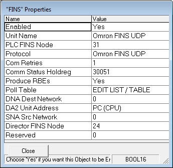
The 'PLC FINS Node' can range from 1 to 254 and should match the last octet of the Ethernet Address of the PLC associated with the communications.
The 'Poll Table' is described later.
The 'DNA Dest Network' uses a value of '0' for Local otherwise set it to 1 to 127 for remote networks.
The 'DA2 Unit Address' has a drop down list of 12 selections, "PC (CPU)", "CPU Bus Unit 0", "CPU Bus Unit 1", "CPU Bus Unit 2", "CPU Bus Unit 3", "CPU Bus Unit 4", "CPU Bus Unit 5", "CPU Bus Unit 5", "CPU Bus Unit 6" "CPU Bus Unit 7", "CPU Bus Unit 8", "CPU Bus Unit 9", and "SYSMAC Netlink Unit". These comprise the 'Destination Unit Address and the default is "PC-CPU".
The 'SNA Src Network' is used for the Source Network Address where "0" is Local otherwise use values from 1 to 127.
The 'RediGate/RediGate FINS Node' parameter is used to set the Elecsys Unit's Node Address from 1 to 255 and should match the last IP OCTET address of the Ethernet card associated with the communications.
Lastly there is a spare 'Reserved' parameter which can range from 0 to 65535.
The documents used in developing the Omron FINS UDP protocol are…
W227_E1_02_FINS_Commands_Reference_Manual.pdf :
W421_E1_02_CS1W_CJ1W_ETN21_Operation_Manual.pdf : Mostly Section 7
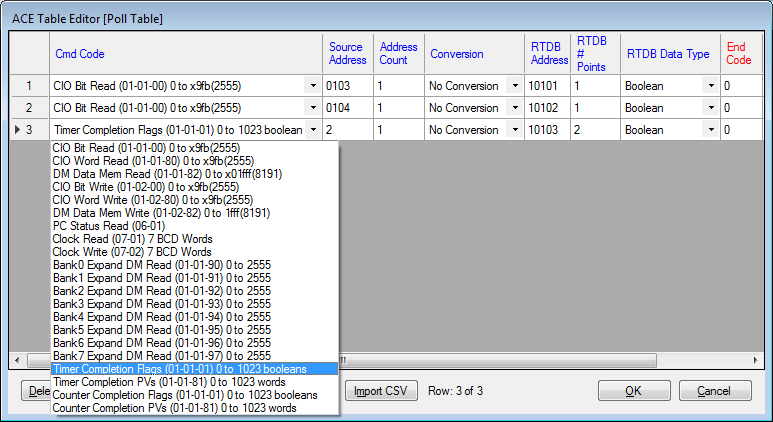
The Omron-FINS UDP protocol is based upon five FINS Command Codes, CIO Bit(01-01-00), CIO Word (01-01-80), DM Data Mem (01-01-82), PC Status (06-01) and Clock (07-01). After March 20, 2017 10 more codes were added, "Bank0 Expansion DM Read (01-01-90)" to "Bank7 Expansion DM Read (01-01-97)" and, "Timer/Counter Completion Flags (01-01-01)" and "Timer/Counter PVs (01-01-81)" .
The Poll Table should have the first set of rows reserved for Mapping Modbus Write commands to Omron Data areas with several rows unused for future changes. Then you can start configuring the Data Read Groups below the spare rows.
Below is a capture of the first five Poll Table Columns with a description of each column.
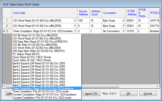
Cmd Code: This column selects the data in the Omron to be read or written. CIO Bit data uses protocol byte 01,01,00 to indicate that boolean bits are being used for reading and writing. CIO Word data uses protocol bytes 01,01,80 to indicate that 16 bit integer words are going to read or written. DM Data Memory uses protocol bytes 01,01,82 to indicate that Data Memory buffers are being identified for reading and writing. Ditto for PC Status and Clock command codes. Older PLCs did not differentiate between Timers and Counters and for them you should only user Timers.
Source Address: This column is used to identify the starting address for the 'Cmd Code' data type.
Address Count: This column is use to determine how many data items in the PLC are being referenced with this row of the poll table.
Conversion: This has a drop down list of five options, "No Conversion", "Byte Swap", "Word Swap", "Byte+Word Swap", "BCD"?
RTDB Address : This column configures the starting RTDB register address associated with the 'Cmd Code' data. The poll table used five digit Modbus address to identify the four major Modbus data areas… 1 to 9999 for Coils (RW), 10001 to 19999 for Discrete Inputs (RO), 30001 to 39999 for Input Registers (RO) and 40001 to 49999 for Holding Registers (RW). This configures where to begin storing data from the Omron Reply into the RediGate/RediGates's RTDB area. More info needed.
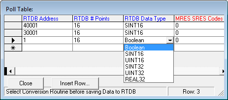
RTDB # Points : This column configures how may RTDB registers will be associated with the FINS data group.
RTDB Data Type: This column has a drop down list of 6 data types, "Boolean", "SINT16", "UINT16", "SINT32", "UINT32" and "REAL32".
MRES SRES Codes : Set to zero if not to be used otherwise this determines where to save the Main/Sub Response Codes from the PLC.
Here is a snippet of documentation about the MRES and SRES….
8-1 Configuration
Response codes for FINS commands consist of two bytes that indicate the result
of executing a command. The structure of the response codes is shown in the
following diagram.
Bit 7 6 5 4 3 2 1 0 7 6 5 4 3 2 1 0
1: PC Non-fatal Error Flag
1: PC Fatal Error Flag
1: Relay Error Flag
First byte Second byte
Main response code (MRES) Sub-response code (SRES)
The main response code (MRES) in the first byte classifies the response and the
sub-response code (SRES) in the second byte indicates details under the
MRES classification.
If bit 7 of the first byte is ON, a network relay error has occurred. Refer to Network
Relay Errors in this section for details on troubleshooting the error.
If bit 6 or 7 of the second byte is ON, an error has occurred in the PC or computer
returning the response. Refer to the operation manual for the device returning
the response for details when troubleshooting the error.