Protocol_TotalFlow
- Former user (Deleted)
- Former user (Deleted)
Screenshots May Differ from Current ACE Release
Many of these protocols were developed using the legacy ACE software, so the screenshots in the example may differ from what you will see in the current version of ACE. These differences are completely aesthetic, and all protocol functionality is supported regardless of the version of ACE you are using.
NOTES ABOUT THE ABB TOTALFLOW DB-2 REGISTER PROTOCOL DEVELOPMENT

Only READ transactions have been supported. Sometime after October 9,2016 the WRITE transactions should have some support. Only WRITES to simple array elements will be supported. Writes to elements of STRUCTURES will not initially be allowed. UPDATE: Nov 21, 2016… Support has been added for writing to the Float Array “3” in the SU Gas Turbine Application of the G4 Simulator. Even though the write was successful, the RediGate’s diagnostics falsely indicate a failure.
Compression is not supported.
Currently only one ‘Register Set’ per poll works as advertised and soon there will be corrected support for multiple ‘Register Sets’ per poll.
TCP/IP version of the protocol will be accomplished by linking into the RediGate/RediGate Terminal Client process.
The documents used in developing the ABB TotalFlow DB2 Register protocol are…
2105193MNAA.pdf : SU Gas Turbine Tube (AGA7) Register definitions.
2105194MNAB.pdf : SU Gas Orifice Tube (AGA3) Register definitions.
IOS SFC G4 Register RevBE.doc : This document describes registers for the G4 XFC I/O System application.
Valve Control Registers G4 RevAD.doc : This document describes registers for the G4 XFC Valve Control application.
XMV Registers RevAC.doc : This document describes registers for the G4 Muti-Variable Transducer application.
WLIO Registers RevAF.doc : This document describes the registers for the Wireless I/O module application.
TFIO Registers G4 RevA3.doc : This document describes the registers for the TotalFlow I/O application.
PID Registers RevAA.doc : This documents describes the registers for the PID Controller and Math Operations application.
SuVCone Tube Registers G4 RevAB.doc : This document describes the registers for the Selectable Units V-Cone Tube application.
Pump Registers G4 Rev CD.doc : This documents describes the registers for the Pump Controller application.
NGC Therms Master Registers RevAA.doc : This document describes the registers for the Therms Master application (NGC might stand for Natural Gas Chomatograph).
US TUBE\AGA3 Tube Registers RevAB.pdf : This document describes the registers for the US Tube Apps \ AGA3 Orifice application.
US TUBE\AGA7 Tube Registers RevAB.pdf : This document describes the registers for the US Tube Apps \ AGA7 Turbine/Linear application.
US TUBE\US VCone Tube Registers RevAB.doc : This document describes the registers for the US Tube Apps \ VCone application.
SU G4 Liquid Tube Registers RevAA.doc : This document describes the registers for the Selectable Units Liquid Turbine Tube application.
Chrom Registers RevAA.doc : This document describes the registers for the Chromatograph analysis application.
NGC BTU Registers RevAB.doc : This document describes the registers for the NGC BTU calculation application.
Tank Registers RevAC.doc : This document describes the registers for the LevelMaster Tank volume calculation application.
Gas Lift RevAE.doc : This document describes the registers for the Gas Lift application with injects gas into the casing to lift fluids up the tubing application.
Holding Registers RevAA.doc : This document describes the registers for the Holding Registers application which needs more reply parsing if “_abParseDef[1]==DTYPE_NULL”. NOT COMPLETED AS OF November 3, 2016.
Plunger Registers G4 RevAL.doc : This document describes the registers for the Plunger Gas Lift Control application which injects gas into the casing to lift plunger and fluids up the tubing.
Oil Transfer Registers RevAC.doc : This document describes the registers for the Oil Custody Transfer application using Level Master information(?).
SU Coriolis_MultiDeviceTubeRegisters_RevAA.doc : This document describes the registers for the Selectable Units Coriolis Multiple Device Tube application.
Pulse Accum Registers G4 RevAB.doc : This document describes the registers for the Pulse Accumulator application.
Pad Registers RevAC.doc : This document describes the registers for the PAD Scheduler application.
All G4 SU NIST14 Registers RevAA.doc : This document describes the registers for All G4 Selectable Units NIST-14 Gas Tube registers application (High CO2 gas concentration?).
Trend Registers RevAA.docx : This document describes the registers for the Trend Files registers application (Not certain what the “Programmable” register types are supposed to be, UINT32 or U24BIT).
Therms Slave Registers RevAA.doc : This document describes the registers for the Therms Slave application.
AutoDiscovery.docx : How to read special System App Arrays to know what Applications are configured into which slots.
Supervisory Frame Implementation.docx : How to calculate the CRC, prepend four character security codes and insert the ABB Device name.
System Registers RevAA.doc : Array definitions for the System Application and the 65+ Application enumeration values.
Totalflow DB2 Register Protocol.docx : Description of message transactions.
The DB2 Register protocol is based upon Vectors X,Y,ZZ addressing. ‘X’ is the slot number (0 to 255) which is running an application. ‘Y’ is used to select one array (of possibly several arrays 0 to 255) of data associated with the application. Array 81 for Application 20 is probably different from array 81 for Application 21. Arrays can be composed of a consecutive series of the same simple data types (UINT8, UINT16, UINT32, Float, Double Float and Strings) or complex structures (Daily Log, AGA7 Tube configuration, etc…). ‘ZZ’ is the starting element in the array and can range from 0 to 65535.
The Poll Table should have the first set of rows reserved for Mapping Modbus Write commands to ABB Data areas with several rows (at least 20) unused for future changes. Then you can start configuring the Data Read Groups below the spare rows. (This might not need to be true if all command data are written to the RTDB and then use a write to a TRIGGER to enable a write which in turn gets its information from the RTDB.)
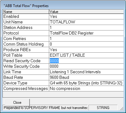
The first read should be from 0.3.0 (Slot Application configuration) and should be enabled when the RediGate is unable to communicate with the ABB device. The suggested technique to enable this poll requires the “Comms Status HoldReg” parameter being set to some input register like 30191. When the RTU is failed then 30191 will contain a “0” and when it is communicating it will contain a “7”. If the “Skip Reg” column (not shown) is set to 30191 with the “Skip Condition” set to ‘Skip if Equal to CONSTANT Value’ and the ‘Skip Value’ set to “7” then the RediGate will attempt to retrieve the SLOT configuration array whenever the Communications are failed. This data is stored in an internal array for each RTU and is used to determine what Arrays are to be associated with each Slot’s Application.
The RediGate’s maximum ABB message packet size is 4000 bytes. The RediGate can issue multiple requests for Vector X,Y,ZZ data in one transaction. A ‘rule of thumb’ should be to not request more than ten messages in a group for optimum communications. When reading structure data you should look up the number of bytes returned by each structure.
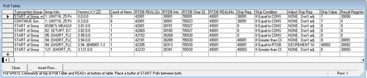
Below is a capture of the first eight Poll Table Columns with a description of each column.
Transaction Group: This enables more than one Poll Record to be issued in one Scan Transaction. The Scan Table record should only reference rows tagged as ‘START of Group’. When the Scan command is issued for the row then all rows tagged with ‘CONTINUE Group’ will included in the transaction until a row tagged as ‘START of Group’ is detected.
Array Info: This column does not actually affect the poll packet but is instead intended to help the user remember the Vector X and Y numbers for different data applications and arrays as shown below.
Vectors X,Y,ZZ: This column is a 31 character field into which the user can simply type in Comma Separated Values (CSVs) or Period Separated Values (PSVs) to be used in a verbatim replacement into the Poll Packet or can be used to reference values stored in the RTDB which can be copied into the Poll Packet. In the above capture Poll Row two’s Packet will be filled with the hex values of “00 03 00 00” as 0,3,0,0 is converted from decimal values. (NOTE: ‘X’ is the SLOT NUMBER. ‘Y’ is the ARRAY NUMBER. ‘ZZ’ is the STARTING ELEMENT in the array.
If the user wants to retrieve data from a RTDB Register(s) and place it into the Poll Packet then instead of using CSVs there is a second technique. This involves starting the string with the “@” symbol, followed by a starting Register address in the RTDB, then a COLON (:), then the Count of Registers followed by a Hyphen (-) and lastly an Element size per register ranging from 1 to 30. You should be able to place two of these @-Strings into the Parameters field. Row 7’s Packet will use the first two values as 03 5E and then read from RTDB Register 40001 for two bytes of variable data. If Register 40001 contains a value of 5 then the four bytes of vector information will be 03 5E 05 00.
Another special feature uses the LESS THAN symbol (<) to instruct the protocol to use a triad of Total VECTOR information stored in three consecutive RTDB registers For example if you read theVECTORs for Slot, Array, Element from 30771, 30072, and 30073 then use “<30771”.
Count of Items: This will limit how many elements of the array will be retrieved from a Poll Reply or it can be used to determine how many Modbus RTDB registers are associated with Write Commands. Writing to structures is not allowed?
RTDB REAL32s : This column configures the starting RTDB REAL32 register address associated with the X.Y.ZZ data. This configures where to begin storing Floating Point data from the ABB Reply in the RediGate’s RTDB area. If the other three RTDB column fields for this row are set to zero then all data items from the ABB Reply will be contained in a series of REAL32 registers.
For now it is best if the ‘RTDB REAL32s’ column is not set to zero for any record even if there is not any Floating point data expected in the ABB Reply. The data sorting logic is not as robust when the REAL32s field is set to zero.
When non-Floating point data is to be stored in the REAL32 area the following rules are used.
1) A Single Byte Character value is first converted into the equivalent Floating Point number and then saved as a four byte IEEE value in the RTDB.
2) A Two Byte Integer value is converted into the equivalent Floating Point number and then saved as a four byte IEEE value in the RTDB.
3) A Character string is packed into four byte segments until no more characters are needed and stored into one or more IEEE RTDB registers.
4) A Double float is stored in two separate IEEE RTDB registers.
RTDB Ints: This column configures the starting RTDB Integer register address associated with the Register Set data. Single byte Character data and two byte Short integers or four byte REGISTER information or four byte Long integers are all defined to be classified as Ints. REGISTER information is saved as three consecutive Integer registers. If the other three RTDB column fields for this row are set to zero then all data items from the Total Flow Reply will be contained in a series of integer registers. The data type of the starting integer register (16-bit or 32-bit or 64-bit) will be used for the entire series of integer registers.
When non-Int16 data is to be stored in the INT16 area the following rules are used.
1) A Single Byte Character value is first converted into the appropriate integer value before being into the RTDB.
2) A four byte REGISTER value is saved as three consecutive Integer RTDB registers.
3) A Character string is packed into two or four byte segments until no more characters are availble and stored into one or more integer RTDB registers.
4) A Double float is stored in four separate Int16 RTDB registers or two Int32 registers.
RTDB Char-32 : This column configures the starting RTDB 32 byte Character String register address associated with the Total Flow String. No other data type is allowed to be packed into the Char-32 RTDB area.
RTDB REAL64s : This column configures the starting RTDB Double Float register address associated with the X,Y,ZZ data. No other data type is allowed to be packed into the REAL64 storage area.
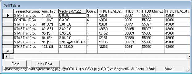
Below are the remaining Poll Table Columns.
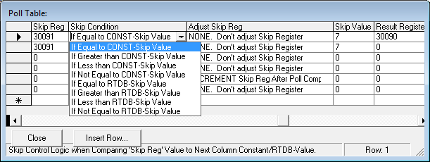
Skip Reg : When this is set to a non-zero value then one or more actions can be applied to the execution of the poll record. Firstly the Poll Record can be skipped when the ‘Skip Condition’ logic is examined to be TRUE. There are four conditions that can be selected when comparing the ‘Skip Reg’ value from the RTDB to the ‘Skip Value’. The conditions are being Equal to, Greater Than, Less Than or Not Equal to the Skip Value. The ‘Skip Value’ is either interpreted as a CONSTANT or as a reference to a register in the RTDB area.
Skip Condition : Used in conjunction with the ‘Skip Reg’ and ‘Skip Value’.
Adjust Skip Reg : Upon successfully completing this poll record (not skipping it) then this option will allow the RediGate to increment or decrement the value referenced in the ‘Skip Reg’ field. If desired the ‘Skip Reg’ will be incremented after each successful poll until it is wrapped back to zero once it reaches 450, 200, 59, 23, 34 or 11. It can also be used to decrement the ‘Skip Reg’ value to zero.

Skip Value : This is either used as a verbatim constant value or as a reference to an register in the RTDB area.
Result Register : If set to a non-zero value then the number of bytes received from this poll record will be saved to the RTDB.
Tested ABB Applications and Arrays
SYSTEM APPLICATION (0): Always in Slot-0.
Array 0 is used for System Strings,
Array 3 is used for System Slot Definitions
All other SYSTEM APPLICATION arrays have support code but have not been tested.
SU TURBINE TUBE GAS APPLICATION (21): AGA7 selectable units. (Many of the simple arrays have support code but have not been tested.) Below are structural records that ‘read’ support is finished and has only been tested against a crude protocol simulator.
Array 81: Recent Measurement record
Array 82: Device Setup record
Array 83: Event Log recent record
Array 84: Day Log record prepended with SHORT FLOW HEADER (SFH)
Array 85: Period Flow record prepended with SFH
Array 94: Day Log record prepend SFH, appended with SU_DAY
Array 95: Period Flow record prepended with SFH, appended with SU_PERIOD
Array 121 : Event Log prepend SFH, with EventLog-Rev3
Arrays 200 to 214 : Single Element of Period Flow Log records
Arrays 220 to 234 : Single Elements of Day Log records
Array 250: Period Flow record (without prepended or appended structures)
Array 251: Day Flow record (without prepended or appended structures)
All other SU GAS TURBINE TUBE simple element arrays have support code but have not been tested.
UNSUPPORTED Structures
SHORT FLOW HEADER (SFH) has Header-Length, DSID, DSID-Revision, Volume-Calc-Method, Record-Length, Number-of-Records.
….UNTESTED Applications….
SU ORIFICE TUBE GAS APPLICATION (20): AGA3 selectable units. (Many of the simple arrays have support code but have not been tested.) Below are structural records that ‘read’ support is finished and has only been tested against a crude protocol simulator.
Array 81: Recent Measurement record
Array 82: Device Setup record
Array 83: Event Log recent record
Array 84: Day Log record prepended with SHORT FLOW HEADER (SFH)
Array 85: Period Flow record prepended with SFH
Array 94: Day Log record prepend SFH, appended with SU_DAY
Array 95: Period Flow record prepended with SFH, appended with SU_PERIOD
Array 121 : Event Log prepend SFH, with EventLog-Rev3
Arrays 200 to 214 : Single Element of Period Flow Log records
Arrays 220 to 234 : Single Elements of Day Log records
Array 250: Period Flow record (without prepended or appended structures)
Array 251: Day Flow record (without prepended or appended structures)
All other SU GAS TURBINE TUBE simple element arrays have support code but have not been tested.
IOS XFC INPUT/OUTPUT XFC APPLICATION (1): IOS Modules support. All of the simple arrays have support code but have not been tested.
Array 4: AI_STRUCTURE that has not been tested yet.
VALVE CONTROL APPLICATION (9): Valve Control support. All of the simple arrays have support code but have not been tested.
Array 3: VALVE NOMINATIONS_STRUCTURE that has not been located yet.
Array 4: VALVE NOMINATIONS_STRUCTURE that has not been located yet.
XMV APPLICATION (12): Multivariable Transducer. All of the simple arrays have support code but have not been tested.
Array 205: AI_STRUCTURE that has not been tested yet.
WIRELESS REMOTE I/O APPLICATION (57): Wireless Remote I/O Transducers. All of the simple arrays have support code but have not been tested.
Array 123: AI_STRUCTURE that has not been tested yet.
Array 124: AI_STRUCTURE that has not been tested yet.
Array 205: AI_STRUCTURE that has not been tested yet.
PID CONTROLLER APPLICATION (63) : TotalFlow PID Controller and Math Operations application. Does not have any structures.
TFIO INTERFACE APPLICATION (101) : TotalFlow Input/Output interfaces application.
SELECTABLE UNITS V-CONE APPLICATION (53) : TotalFlow Selectable units V-Cone Tube application. Simple arrays only. Later there will be support for structures.
PUMP CONTROLLER APPLICATION (16) : TotalFlow Pump Controller application including Modbus stuff.
THERMS MASTER APPLICATION (11) : TotalFlow Therms Master application including Modbus stuff.
US AGA3 TUBE APPLICATION (4) : TotalFlow US AGA3 Orifice Tube application.
US AGA7 TUBE APPLICATION (5) : TotalFlow US AGA7 Turbine/Linear Tube application.
US V-CONE TUBE APPLICATION (23) : TotalFlow US V-CONE Tube application.
SU LIQUID TUBE APPLICATION (38) : TotalFlow Selectable Units Liquid Turbine Tube application.
CHROMATOGRAPH APPLICATION (40) : TotalFlow Chromatograph registers application.
NGC BTU APPLICATION (41) : TotalFlow NGC BTU registers application.
LEVELMASTER APPLICATION (15) : TotalFlow Tank Level Master registers application.
GAS LIFT APPLICATION (68) : TotalFlow Gas Lift registers application.
HOLDING REGISTERS APPLICATION (10) : TotalFlow Holding Registers application. Needs special detection of _abParseDef[1]==DTYPE_NULL to calculate BytesPerRegister (1,2,4 or 24). TBC.
PLUNGER LIFT CONTROL APPLICATION (56) : TotalFlow Plunger Gas Lift Control registers application.
OIL CUSTODY TRANSFER APPLICATION (37) : TotalFlow Oil Custody Transfer registers application.
SU MULTIPLE CORIOLIS TUBE APPLICATION (55) : TotalFlow Selectable Units Multiple Coriolis Tube registers application.
PULSE ACCUMULATOR APPLICATION (32) : TotalFlow Pulse Accumulator registers application.
PAD SCHEDULER APPLICATION (62) : TotalFlow PAD Scheduler registers application.
SU NIST14 GAS TUBE APPLICATION (51) : TotalFlow Selectable Units NIST-14 Gas Tube registers application.
TREND FILE APPLICATION (7) : TotalFlow Trend Files registers application.
THERMS SLAVE APPLICATION (14) : TotalFlow Therms Slave registers application.
SHORT FLOW HEADER (SFH) has Header-Length, DSID, DSID-Revision, Volume-Calc-Method, Record-Length, Number-of-Records.
….FINAL NOTES….
Should the RediGate/RediGate always send the ‘Supervisory Frame’ multiple times before every transaction?
// Numeric APPLICATION Listing
// 0, 1, 4, 5, 7, 9, 10, 11, 12, 14, 15, 16, 20, 21, 23, 32, 37, 38, 40, 41, 51, 53, 55, 56, 57, 62, 63, 68, 101,