Protocol_Modbus-Master
- Former user (Deleted)
- Jon Tandy

Product Information
Full information about other Elecsys products is available on our website at www.elecsyscorp.com and the RediGate Product Support page.
Product Support
Tel: +1-913-890-8905
Fax: +1-913-982-5766
Email: idc-support@elecsyscorp.com
Headquarters, Sales, Support & Manufacturing
Elecsys Corporation
846 N Mart-Way Court
Olathe, KS 66061
Tel: +1-913-647-0158
Fax: +1-913-982-5766
Email: info@elecsyscorp.com
While Elecsys may assist customers with their choice of products, the final choice of product for a specific application is entirely the responsibility of the buyer. Elecsys' entire liability with respect to its products or systems is defined in the Elecsys standard terms and conditions of sale.
Any example code is provided only to illustrate the use of Elecsys products. No warranty, either expressed or implied, is made regarding any example code provided by Elecsys and Elecsys shall incur no liability whatsoever arising from any use made of this code.
Disclaimers
The information in this manual is believed to be accurate at the time of publication. Elecsys Corporation assumes no responsibility for inaccuracies that may be contained in this document and makes no commitment to update or keep current the information contained in this manual. Elecsys Corporation assumes no responsibility for any infringements of patents or other rights of third parties that may result from its use. Elecsys Corporation reserves the right to make changes or improvements to this document and/or product at any time and without notice. While Elecsys may assist customers with their choice of products, the final choice of product for a specific application is entirely the responsibility of the buyer. Elecsys' entire liability with respect to its products or systems is defined in the Elecsys standard terms and conditions of sale.
Any example code is provided only to illustrate the use of Elecsys products. No warranty, either expressed or implied, is made regarding any example code provided by Elecsys and Elecsys shall incur no liability whatsoever arising from any use made of this code.
Electrostatic Discharge (ESD) Protection
These units contain devices that could be damaged by the discharge of static electricity. At all times, please observe industry standard ESD precautions when handling the unit.
![]() WARNING: DO NOT CONNECT OR DISCONNECT CABLES WHEN ENERGIZED, UNLESS POWER HAS BEEN REMOVED FROM THE EQUIPMENT OR THE AREA IS KNOWN TO BE FREE OF IGNITABLE CONCENTRATIONS OF FLAMMABLE SUBSTANCES.
WARNING: DO NOT CONNECT OR DISCONNECT CABLES WHEN ENERGIZED, UNLESS POWER HAS BEEN REMOVED FROM THE EQUIPMENT OR THE AREA IS KNOWN TO BE FREE OF IGNITABLE CONCENTRATIONS OF FLAMMABLE SUBSTANCES.
© 2024 Elecsys Corporation
Table of Contents
Introduction
The RediGate Configuration Manual describes the configuration of many of the RediGate's standard features using the ACE program. This document gives additional instructions for configuring the RediGate to use the following protocols:
- Modbus RTU (serial) Master
- Modbus ASCII (serial) Master
- Modbus RTU (TCP) Master
- Modbus ASCII (TCP) Master
- Open Modbus/TCP Master
See the following Quick Start example configurations:
The RediGate is a multi-application remote data communications computer/data integration device. It provides a wide array of SCADA and other communication and logic processing functionality. In order to configure the operational characteristics of the RediGate, Elecsys provides the ACE Configuration Editor. This manual assumes that the user is already familiar with the use of ACE and that the RediGate being configured includes software support for the above protocols.
Within the ACE Editor, each configuration object is represented by an icon and contains general properties and specific fields that provide operational settings for the RediGate. This manual provides reference information on the configuration objects within the ACE Editor, specific to the FieldUnit protocol(s) listed above.
To configure as a UDP/IP Master, see RediGate UDP Protocol Master.
Modbus Protocol Description
This document is not intended to provide a detailed description of the protocol(s) involved, nor to disclose proprietary information that may belong to other parties. Depending on the protocol, it may be necessary to refer to other vendor protocol documentation or device configuration details to understand how the RediGate should be configured to interface with it. This section provides a brief discussion of the protocol for the purpose of understanding the RediGate's configuration objects.
Modbus is a poll-response (or master-slave) protocol. Modbus protocol devices are addressed with a number from 1 to 255. A host system requests data from a Modbus device using a Function Code, a zero-based Offset, and a Count of registers. The Function Code determines the type of data, and the Offset specifies which starting register to request within that data type, starting from 0. The device will respond to a request by returning the specified Count of registers. Traditionally, Modbus device vendors use a 5-digit Address notation to refer to these registers (for example, 40,001); however, some manufacturers use the Function/Offset method or a different non-standard Address notation to identify registers (such as 400,001).
Typical Modbus address registers and function codes are listed below, along with the traditional Starting Address notation.
| Function Code | Register Group | Starting Address | Read/Write Read-Only | Description |
|---|---|---|---|---|
| 1 | Coil Registers | 00,001 | Read | Coils are used for digital outputs or other general purpose Boolean values. |
| 2 | Status Registers | 10,001 | Read-only | Status Registers are Boolean values, typically used for digital status inputs. |
| 3 | Holding Registers | 40,001 | Read | Holding Registers are the most commonly used register, used for analog outputs, and general purpose integer or floating point data, strings, etc. |
| 4 | Input Registers | 30,001 | Read-only | Input Registers are typically used for analog inputs. |
| 5 | Write Coil | 00,001 | Write | Write a single Coil. |
| 6 | Write Holdreg | 40,001 | Write | Write a single Holding Register. |
| 15 | Write Multiple Coils | 00,001 | Write | Write multiple Coil Registers. |
| 16 | Write Multiple Holdregs | 40,001 | Write | Write multiple Holding Registers. |
For example, using a Function Code=3, Offset=0, and Count=6 would request the registers commonly notated as 40,001-40,006. The following message shows this poll and response for a device number 21 (0x15). The values returned from the registers in this example are 0001 through 0006 (underlined below).
Poll:     15 03 00 00 00 06 C6 DC
Response: 15 03 0C 00 01 00 02 00 03 00 04 00 05 00 06 C8 20
Holding Registers and Input Registers commonly hold 16-bit data. Often, pairs of 16-bit registers are also used to represent 32-bit integers or floating point data.
For instance, in a device that uses register pairing, the host might request 41,001 and 41,002 (two 16-bit values), and the host is responsible for assembling them into a single 32-bit value. The first register might contain the most-significant 16-bit word (big-endian), or it might contain the least-significant 16-bit word (little-endian), depending on the design of the device.
In other devices, a single register (e.g., 41,001) might return a 32-bit value per address location. Or it might use analog registers to contain packed Booleans, one or two ASCII character strings per register, etc. The system designer must become acquainted with the data and address format used by a Modbus device in order to correctly configure the RediGate to request and interpret the device data.
The Modbus master/host must be configured according to the requirements defined by the device. The RediGate has a very flexible and full-featured configuration that allows it to communicate successfully with nearly all Modbus devices.
Modbus ASCII is an older ASCII-based protocol that uses a less robust LRC error checking algorithm. It is not used much anymore.
Modbus RTU (or Modbus Binary) is the most common protocol for Modbus over serial communications and uses a more robust CRC error checking. The RediGate can do Modbus ASCII or RTU over a serial (RS-232 or RS-485) circuit.
Modbus TCP-Encapsulated – The RediGate can encapsulate either RTU or ASCII Modbus protocol into TCP/IP packets (this would be suitable for communication to a Modbus device through a Terminal Server). This includes the Modbus CRC at the end of the message. The TCP port number is user-definable.
Open Modbus/TCP is a variation of Modbus RTU that is only used for TCP/IP networks. It uses the same basic message structure, but it adds 6 bytes to the beginning and removes the CRC from the end of each message. Open Modbus/TCP uses TCP port 502 as standard.
Note that both Modbus TCP-Encapsulated and Open Modbus/TCP use TCP/IP protocol to transport Modbus protocol messages, but the contents of data packets are slightly different. Be aware that some devices use one or the other protocol type, and they may use somewhat different terminology to refer to these options. If the device uses port 502, it is almost certain that the protocol is Open Modbus/TCP. If the device vendor provides documentation on the binary protocol structure, the presence or absence of the Modbus CRC is another way to distinguish the two protocols.
The following sections describe the ACE objects used for Modbus Master, object properties (including constraints on the Instance number), and object fields and their possible values required to configure for the given protocol(s). The object structure in ACE is hierarchical, with each object existing under a certain parent object. For instance, the FieldUnit is the child of one of several types of Circuit objects, either serial or network type (" System>Clients>Master Channels>Master Channel>Circuit").
The Description and Enabled properties are included in ACE as part of each object but are not mentioned here. The "UFF External" property is only mentioned for the objects where it is typically used, but should normally be left unchecked.
Modbus Master Channel
The structure of ACE objects for a Master Channel used for Modbus protocol is shown below:
| Modbus Serial | Modbus TCP-Encapsulated | Open Modbus/TCP |
| |
|
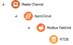
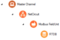
The RediGate uses the Master Channel and its child objects to define the RediGate's ability to act as a master for reading or writing other devices using one or more device protocols. All master protocols use the same basic structural definition, requiring at least four ACE objects to be configured:
- The Master Channel defines the sequence and timing of periodic scans of the device, independent of protocol.
- The Circuit (network or serial) defines the physical connection to the device.
- The FieldUnit object defines the protocol-specific characteristics and poll definitions for the device.
- The Real-time Database (RTDB) defines a data structure for storing information obtained from each physical field device.
- Other optional child objects under the RTDB or FieldUnit provide other features for acting on the device's data.
In the Master Channel configuration, make sure that the Response Timeout is set long enough to receive replies for the given network and field devices. Add rows in the Scan Table for each poll in each FieldUnit that is required to be scanned in real-time.
For general information on configuring Master Channels, see the RediGate Configuration Manual.
AsyncCircuit, NetCircuit
As with most FieldUnit types, Modbus Master requires either an AsyncCircuit for serial (RS-232 or RS-485) devices or a NetCircuit for TCP/IP devices (TCP-Encapsulated Modbus or Open Modbus/TCP).
![]()
![]()
For the AsyncCircuit, choose the serial port to use for the communication (COM2 on RediGate 100 series, or one of several COM ports on the RediGate 400 series).
![]()
![]()
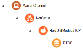
For the NetCircuit, use a Circuit Type of “Network Circuit" and set the Master Network Port to be the TCP/IP port number used by the device for Modbus communication (if using Open Modbus/TCP, this should typically be port 502). Enter the Destination Address (device IP address) in the Connect Table.
For general information on configuring circuits or AsyncPorts, see the RediGate Configuration Manual.
AsyncPort
![]()
![]()
If using an AsyncCircuit for serial devices, make sure to include an COM port (System → Networks → AsyncPort) object in the configuration with the instance number matching the physical COM port, and the baud rate corresponding to the field device’s setting.
See the RediGate Configuration Manual for information on configuring the AsyncPort.
Modbus FieldUnit
![]()
![]()
![]()
A Modbus FieldUnit object contains unique information for each physical field device that uses the Modbus communication protocol, defining parameters for how data is read and written for the device.
| Attributes | Function |
|---|---|
| Object Type | FieldUnitModbus32 (any Modbus type: RTU or ASCII, Serial or TCP-Encapsulated, and Open Modbus/TCP) FieldUnitModbusTCP32 (Open Modbus/TCP only) |
| Parent(s) | System → Clients → Master Channels → Master Channel → AsyncCircuit (serial) System → Clients → Master Channels → Master Channel → NetCircuit (TCP) |
| Instance | Must be unique under a Circuit. |
| The FieldUnit must have an RTDB child object defined under it. | |
| Properties | Values |
|---|---|
| Unit Name | Enter the field unit name. Unit name is displayed in diagnostic menus, in HCP diagnostic screens, and may be used as part of an MQTT topic name. |
| Unit Address | Enter the actual field unit address which is configured in the device being polled. Use a valid Modbus address, 1 to 255, for the device being polled. |
| Protocol | Binary Modbus 32 Unit – Modbus RTU (Binary), serial or TCP-encapsulated ASCII Modbus 32 Unit – Modbus ASCII, serial or TCP-encapsulated Open Modbus TCP or Modbus-TCP 32 Unit – Open Modbus/TCP |
| Com Retries | Enter the number of communication retries after a failed poll attempt. If a poll attempt fails, the RediGate will issue the poll again up to the configured number of "Com Retries" before the field unit is declared failed. For devices on a Network Circuit, you should probably keep the number of protocol retries low (0 or 1), because TCP/IP has its own network retries. |
| Comm Status Holdreg | Enter the starting holding register to contain the communication status for this FieldUnit. Each Comm Status takes 5 registers, beginning at the register configured in this parameter. The Comm Status Holdreg for each field unit in a configuration must be defined such that the five registers do not overlap other registers being used. If the register is defined in the 30,xxx address range, the status values will be stored in the local device's RTDB (i.e., the RTDB defined as a child to this FieldUnit). If the register is in the 40,xxx range, the values will be stored in the Status/Control Field Unit RTDB. The Comm Status Holdreg is optional, and can be set to 0 to disable the storage of status registers. See the section Communication Status Registers in the RediGate Configuration Manual for a description of the five Comm Status Register contents. |
| Produce RBEs | Select this option to determine whether to produce a Report by Exception (RBE) flag when data in this unit's RTDB changes. In the RTDB, for every data point, there are potentially 4 RBE flags associated with every data point. When the data point changes, the RBE flags are set. The RediGate's HCP and MQTT publishing processes use these flags to determine when new data needs to be reported. |
| Poll Table | Click the Edit Table button to define the polls to be sent to this FieldUnit. Note that the Poll Table only defines how the protocol is defined to operate for each set of data defined in the polls. The Poll Table doesn’t actually do any of the polling itself. If you want any of these polls to be sent to the FieldUnit on a regular basis, it should be referenced in one or more Scan Table entries in the Master Channel. Poll Table entries may be defined which are only used for pass-through writing to the device, not scanned regularly by the Master Channel. Protocol-specific properties for the Poll Table are described in the following table. |
| Poll Table Properties | |
|---|---|
| Properties | Values |
| Source Register | Enter the starting source register in the device to begin polling data. This will be found in the documentation for the device, based on the information that you want to obtain. The format of the Source Register depends on the configuration of the Source Format, described below. For OFFSET source formats, the Source Register should be entered as a zero-based Offset (Coils or Holding registers only). For other Source Formats, the Source Register must be entered as a 5-digit absolute address. |
| Source Format | Select the data type of the data being read in this row of the Poll Table. See below for under Configuring Source Format for more details on this option. |
| Count | Enter the count of points to read from the device. For everything other than Strings, the Count includes the number of entities (Boolean, 16-bit, 32-bit, etc.) being requested, based on the Source Format setting listed above. This will typically also be the number of Destination Registers used by the poll. For String data types, the Count must be configured to match whatever convention is used in the Modbus device, and it must be defined such that the Modbus response contains the correct number of response registers (multiples of 8 bytes for String-8, multiples of 16 bytes for String-16, etc.). See below under “Configuring String Data Formats” for more details on the String data types. |
| Destination Register | Enter the starting destination register within the field unit's RTDB into which the Write Count of data points will be stored. These registers must be configured in the RTDB object. The Destination Register type should be chosen based on the Source Format of the data points defined on this row of the Poll Table:
|
| Comment | The Comment column is an optional field, allowing a description to be entered for each row in the table. This is only for the user and has no effect on the operation of the RediGate. |
Configuring Source Format
Different manufacturers use a variety of non-standard formats to represent data using the Modbus protocol. The RediGate provides many options to read and interpret data from a device in any byte order. Sometimes trial and error is necessary to get the configuration correct so that data is represented in the RTDB correctly.
Modbus protocol typically transmits each 16-bit value in “big endian” format (most significant byte, MSB, is transmitted first, followed by the least significant byte, LSB). When requesting 32-bit values, there is no universal standard for how 32-bit Modbus is to be transmitted on the wire. Either the most-significant word (MSW) or least-significant word (LSW) may be stored in the device first, and thus transmitted first in the Modbus protocol messages.
The Poll Table list includes a mnemonic device ("HLhl") and a verbal description of each source format, to help the user identify the different Source Formats.
- The “H” and “L” indicate the relative positions of the high and low bytes within each word.
- “HL” and “hl” indicate the relative positions of the high and low order 16-bit words.
- Thus, the Source Format labeled “Little-Big Endian (hl HL)” indicates the data is interpreted as LSW first followed by MSW; whereas “Big-Big Endian (HL hl)” indicates the data is interpreted as MSW first followed by LSW. These are the two most common methods of polling 32-bit data from Modbus devices.
The following tables give a list of the Modbus Source Format options with an explanation of each. The formats listed in Bold Italic are the more commonly used selections. For each non-OFFSET format, the Source Format column should contain an absolute address (10,001, 40,001, etc.).
| Boolean Source Formats | Description | Meaning |
|---|---|---|
| Boolean | Binary (single bit) register | Single on/off bit occupies a register |
| UnPack16-Boolean | Integer to bit conversion | Integer source register is stored as individual bits in Boolean destination registers, parsed in order of LSB to MSB bits from each 16-bit integer word in the Modbus message. |
| Reverse8-Boolean | Integer to bit conversion | UnPack type with reversed bit order. Integer values are converted to Boolean destination registers, parsed in order of MSB to LSB from each 8-bit byte in the Modbus message. |
| Integer/Float Source Formats | Description | Meaning |
|---|---|---|
| 16 bit register (HL) | Big Endian 16-bit register | Typical 16-bit register type. |
| 32 bit register (hlHL) | Little-Big Endian 32-bit register | One numbered register in the device includes 4 bytes of data, transmitted in Little-Big Endian byte order. |
| 16 Bit Pair L/B Endian (hl_HL) | Little-Big Endian 16-bit pair of registers | Field unit includes pairs of registers, where each register includes 2 bytes of data. Bytes transmitted in Little-Big Endian byte order (LSW first). |
| 32 Bit B/B Endian (HLhl) | Big-Big Endian 32-bit register | One numbered register in the device includes 4 bytes of data, transmitted in Big-Big Endian byte order. |
| 16 Bit Pair B/B Endian (HL_hl) | Big-Big Endian 16-bit pair of registers. | Field unit includes pairs of registers, where each register includes 2 bytes of data. Bytes transmitted in Big-Big Endian byte order (MSW first). |
| 16 Bit L Endian (LH) | Little Endian 16-bit register | Like 16-bit register, byte order reversed. |
| 32 Bit L/L Endian (lhLH) | Little-Little Endian 32-bit register | Like 32-bit register, but with byte order reversed (in pairs) from standard Modbus. |
| 16 Bit Pair L/L Endian (lh_LH) | Little-Little Endian 16-bit pair of registers. | Like 16-bit pair L/B register type, byte order reversed. |
| 32 Bit B/L Endian (LHlh) | Big-Little Endian 32-bit register | Like 32-bit B/B register type, but with byte order reversed from standard Modbus. |
| 16 Bit Pair B/L Endian (LH_lh) | Big-Little Endian 16-bit pair of registers. | Like 16-bit pair B/B register type, byte order reversed. |
| CMD-LOG-TO-STRING32 | Log output commands to String register | Must use Destination RTDB type of String32. When a command output is written to the field device, a String value is stored giving information about the command. If the Count is greater than 1, then multiple String-32 registers will contain a history (ring buffer) of the last several commands. This feature can be used to provide a SCADA or MQTT host with information on command output history. For instance, if Count is 4 and Destination Register is 48001, then the first four command outputs will be logged to 48001, 48002, 48003, and 48004. If a 5th command is received, it will overwrite the value in 48001. Examples of String-32 contents for logged data:
|
The following “OFFSET” formats are equivalent to the Source Format types above in byte and word order, but they allow the configuration to identify the source register using the "Function Code / Offset" convention. The OFFSET type of Source Format is sometimes necessary for Modbus devices that have coil registers greater than 9999 or holding registers numbered higher than an offset of 25,534 (i.e., higher than an absolute address of 65535).
For each OFFSET type, the Source Format column should be configured as a number from 0 to 65535, which is an offset from the first coil register (function code 1) or the first holding register (function code 3). Only Modbus commands 1 and 3 are currently supported for reading OFFSET types (with corresponding Modbus write function codes 5, 6, 15, and 16).
| OFFSET Source Formats | Description | Meaning |
|---|---|---|
| OFFSET Coils 0 to 65535 | Binary (single bit) registerBinary (single bit) register | Use Modbus command 1 with offset (starting from 0) as the Source Register to request Boolean coils. |
| OFFSET 16 bit Hreg (HL) 0 to 65535 | Big Endian 16-bit register | Use Modbus command 3 for all following command formats. Typical 16-bit holding register, but requested with Source Register as an offset (starting from 0). |
| OFFSET 32 bit Hreg (hlHL) 0 to 65535 | Little-Big Endian 32-bit register | 32-bit holding register, with Source Register as an offset |
| OFFSET 16 BitPair L/B Endian (hl HL) 0 to 65535 | Little-Big Endian 16-bit pair of registers | 32-bit value stored as pairs of registers, requested with Source Register as an offset. Bytes transmitted in Little-Big Endian byte order (LSW first). |
| OFFSET 32 Bit B/B Endian (HLhl) 0 to 65535 | Big-Big Endian 32-bit register | Each of the OFFSET Source Format types use the same Endian notation as in the previous table of Source Formats. |
| OFFSET 16 Bit Pair B/B Endian (HL hl) 0 to 65535 | Big-Big Endian 16-bit pair of registers. | |
| OFFSET 16 Bit L Endian (LH) 0 to 65535 | Little Endian 16-bit register | |
| OFFSET 32 Bit L/L Endian (lhLH) 0 to 65335 | Little-Little Endian 32-bit register | |
| OFFSET 16 Bit Pair L/L Endian (lh LH) 0 to 65535 | Little-Little Endian 16-bit pair of registers. | |
| OFFSET 32 Bit B/L Endian (LHlh) 0 to 65535 | Big-Little Endian 32-bit register | |
| OFFSET 16 Bit Pair B/L Endian (LH lh) 0 to 65535 | Big-Little Endian 16-bit pair of registers. |
Examples of Source Format
The Endian source formats above define the byte order in which to interpret the data received from the Field Unit in response to the poll. A few illustrations are given below:
Example #1:
Field device includes ten 16-bit integers, transmitted in normal Modbus format, starting at the address 40,001. Poll Table should be configured for:
Source Register = 40,001
Source Format = 16 bit register (HL)
Count = 10
Destination Register should be a 16-bit RTDB location.
Example #2:
Field device includes four IEEE floating point values, stored in registers 40,001-2, 40,003-4, 40,005-6, and 40,007-8. Because the registers are listed as odd-numbered registers, the device is using pairs of 16-bit registers to represent the 32-bit IEEE values. Thus, the Poll Table should be configured for:
Starting Address = 40,001
Source Format might be "16 Bit Pair L/B Endian (hl HL)” or “16 Bit Pair B/B Endian (HL hl)”, depending on the word order of the registers. (If the odd numbered registers contain the most-significant word, then use the B/B Endian format.)
Count = 4 (this is the count of four 32-bit entities, not eight 16-bit registers)
Destination Register should be a 32-bit RTDB location.
Configuring String Data Formats
The Modbus Poll Table includes several different types for String (ASCII) data. There is no common standard among Modbus devices as to how String data should be stored. The RediGate is only able to read String data in certain increments of ASCII characters (8, 16, or 32 bytes per destination RTDB register). The “Count” column indicates the count of registers that will be included in the Modbus message. As with all Modbus messages, a maximum of 255 total bytes per message are allowed.
For example, if the Modbus device stores ASCII characters in 16-bit registers (two characters per register), then for the String-8 data type you must poll for multiples of 4 source registers (“Count” in the Poll Table should be 4, 8, 12, etc.). For the String-16 data type, the “Count” should be 8, 16, 24, etc.
However, if the Modbus device stores ASCII characters in 32-bit registers (four characters per register), you still need to set the “Count” to poll for multiples of 32-bit registers, so that the response comes back in groups of 8, 16, or 32 ASCII characters, depending on the Source Format chosen (for instance, for String-8 data use a count of 2, 4, 6, etc.). Or, if a single Modbus register contains the entire string, the count should be 1 per string register.
| String Source Formats | Description | Meaning |
|---|---|---|
| String-8 (abcdefgh)String-8 (abcdefgh) | 8-character String request8-character String request | Request sets of four 16-bit registers, returning 8 ASCII characters, which should be stored into STRING32 or STRING256 RTDB registers. Only 8 characters are stored into each RTDB register (multiple register reads are stored into sequential RTDB string registers). Example: Omni flow computer in Omni mode returns 8 characters in response to a read request with Count=1. But in Modicon mode, you have to request a Count=4 registers in order to receive 8 characters. The RediGate Modbus driver will accept the bytes that are returned in whatever quantity, regardless of the mode, and store them into the RTDB in groups of 8 until the whole response message is processed. |
| String-8 Swapped (badcfehg) | 8-character String request, byte-swapped | Like the String-8, only each pair of bytes (MSB/LSB in each register) is reversed. Only 8 characters are stored into each RTDB register (multiple register reads are stored into sequential RTDB string registers). |
| String-16 (abcdefghijklmnop) | 16-character String request | Request sets of eight 16-bit registers, returning 16 ASCII characters, which should be stored into STRING32 or STRING256 RTDB registers. Only 16 characters are stored into each RTDB register (multiple register reads are stored into sequential RTDB string registers). |
| String-16 Swapped (badcfehgjilknmpo) | 16-character String request, byte-swapped | Like the String-16, only each pair of bytes (MSB/LSB in each register) is reversed. Only 16 characters are stored into each RTDB register (multiple register reads are stored into sequential RTDB string registers). |
| String-32 (abcdefghijklmnop) | 32-character String request | Request sets of sixteen 16-bit registers, returning 32 ASCII characters, which should be stored into STRING32 or STRING256 RTDB registers. Only 32 characters are stored into each RTDB register (multiple register reads are stored into sequential RTDB string registers). |
| String-32 Swapped (badcfehgjilknmpo) | 32-character String request, byte-swapped | Like the String-32, only each pair of bytes (MSB/LSB in each register) is reversed. Only 32 characters are stored into each RTDB register (multiple register reads are stored into sequential RTDB string registers). |
| OFFSET String-8 (abcdefgh) 0 to 65535 | 8-character String request, using Offset instead of register address | Like String-8, but the Source Register is an offset from register 40001, not an absolute address (using Modbus command 3). |
| OFFSET String-8 Swapped (badcfehg) 0 to 65535 | 8-character String request, byte-swapped, using Offset instead of register address | Like String-8 Swapped, but using Source Register as offset. |
| OFFSET String-16 (abcdefghijklmnop) 0 to 65535 | 16-character String request, using Offset instead of register address | Like String-16, but using Source Register as offset. |
| OFFSET String-16 Swapped (badcfehgjilknmpo) 0 to 65535 | 16-character String request, byte-swapped, using Offset instead of register address | Like String-16 Swapped, but using Source Register as offset. |
| OFFSET String-32 (abcdefghijklmnop) 0 to 65535 | 32-character String request, using Offset instead of register address | Like String-32, but using Source Register as offset. |
| OFFSET String-32 Swapped (badcfehgjilknmpo) 0 to 65535 | 32-character String request, byte-swapped, using Offset instead of register address | Like String-32 Swapped, but using Source Register as offset. |
Example of writing to String registers
All of the String Source Formats above apply to reading ASCII data, but what about writing strings? Because of the logic involved in processing Modbus write commands and the differences in how String polls are defined, the Poll Table must be defined carefully in order for String writes to be handled correctly.
Below is an example of a Poll Table containing a command to read String-8 registers from a device that stores ASCII data with two bytes per 16-bit register. The Poll Table reads 12 registers from the device, receives 24 bytes in response, parses the message into three String-8 values, and stores the resulting data into 48001-3 (40033‑36 à 48001, 40037‑40 à 48002, and 40041‑44 à 48003).
| Source Register | Source Format | Count | Destination Register |
| 40033 | String-8 | 12 | 48001 |
If a host writes to 48001, the RediGate Modbus driver will correctly write the four registers (40033‑36) back to the device. But writing to 48002 or 48003 will not work correctly. In order to make all of the String registers write to the correct locations, there must be additional polls defined in the Poll Table (which do not need to be scanned in the Scan Table), as follows:
| Source Register | Source Format | Count | Destination Register | Scanned in Scan Table? |
| 40041 | String-8 | 4 | 48003 | no |
| 40037 | String-8 | 4 | 48002 | no |
| 40033 | String-8 | 4 | 48001 | no |
| 40033 | String-8 | 12 | 48001 | YES |
Note the following about the Poll Table above:
- The three extra polls map each RTDB Destination Register to the starting Source Register explicitly. These polls do not need to be included in the Scan Table of the Master Channel, because they will not be read continuously. Their only purpose is to map outputs for write commands.
- The non-scanned polls must be defined in reverse order based on Destination Register.
- The non-scanned polls must be defined above the scanned poll (higher in the table). This allows the poll table lookup to find a match for the RTBD register and map to the correct Source.
Modbus RTDB
See the RediGate Configuration Manual for information on configuring the RTDB.
Modbus Specific Outstation (SOS)
![]()
![]()
The Master Channel, Circuit, Field Unit, and RTDB object properties are generally very similar for all Field Units, independent of the protocol being used. This is designed so that a common structure is used for handling protocols in a similar way. However, depending on the protocol, sometimes it is necessary to have special protocol-specific options for the Field Unit. Rather than modifying the common channel structures, it is preferred to have an additional object that defines these special characteristics.
The SOS object contains additional features specific to a particular Field Unit protocol. In this document, "SOS" stands for "Specific Outstation," meaning specific properties that may be unique for a given protocol. This section describes the SOS object for Modbus units. Field Units using protocols other than Modbus may have their own unique SOS object defined.
The Modbus SOS object is a powerful, complex tool which allows a user to modify the normal structure of the Modbus polling protocol, based on results of preceding polls, or based on controls that are received from a Modbus host or ISaGRAF logic. Criteria can be specified which, if true, cause the polls defined in the Modbus Poll Table to be modified or skipped. This is useful in certain applications, such as reading log data from certain Modbus flow computers. This feature is sometimes referred to as "self-modifying polls".
If these special additional capabilities of the Modbus polling are not needed, this object may be omitted from the configuration.
| Attributes | Function |
|---|---|
| Object Type | SosMod |
| Parent(s) | System → Clients → Master Channels → Master Channel → Circuit → Modbus Field Unit |
| Instance | Must be 0 |
| Properties | Values |
|---|---|
| Poll Modification Defs | Click the Edit Table button to define the special characteristics needed for the Modbus protocol modification on this Field Unit. |
| Poll Index | This refers to the poll numbers defined in the Field Unit Poll Table. The poll message whose number appears in this row will be modified as specified in the remainder of this row. If several rows refer to the same poll number, all modifications will be evaluated before modifying this poll transmit message, in case one condition specifies "no modification". |
| Trig. Addrs | Enter the Modbus address location in this RTU's RTDB to use for a Trigger Address. If the Trig Address contain the exact value as specified in the "Trig Value" parameter, then this SOS row becomes active, and the modification of this poll message will take place. The values in the Trig Address RTDB registers may be modified by a polling process, or by ISaGRAF or POD logic. |
| Trig. Value | Enter the value which, if found at the Trig Addrs. location, will cause the poll message modification to take place. This value may be between 0 and 65535 inclusive. If the Trig Addrs is a Boolean register, the valid values are 0 and 1. |
| Tx Start Byte | Unless using a "Skip" option for the Fill Control, the SOS table allows bytes in a Modbus message to be modified before the poll is sent. The poll byte modification is controlled by the Tx Start Byte, Tx #Bytes Filled, Fill from Addrs. and Fill Control parameters. Enter the starting byte of the Modbus poll command to be modified. Modbus poll Tx bytes that might be used for this option typically include:
|
| Tx #Bytes Filled | Enter how many bytes in the poll command are to be modified starting at the Tx Start Byte. |
| Fill from Addrs | Enter the Modbus location in the RTDB containing the bytes to use for the poll modification. The values in this RTDB location(s) should be filled as required, before the Trigger occurs, either by ISaGRAF, an external host, or as the result of another poll to the Field Unit. |
| Fill Control | This parameter allows certain variations when executing the self-modifying poll. If either of the "Skip" options is used, the poll is either skipped or not skipped based on the value of the Trig. Addrs. Otherwise (if using a non-Skip option on this SOS table row), bytes in the Modbus poll will be modified before sending to the device. This can be useful for some complex operations, such as working with non-standard Modbus in certain flow computers. Options available for this parameter are: No Conversion (LSB first) - Bytes from the Fill from Addrs registers are used with no conversion, as 16-bit values. Byte Swapping (MSB first) - Bytes from the Fill from Addrs. Register are put into the transmit message MSB first, followed by LSB. Fill using LSB only - Use this option if the Fill from Addrs register contains an 8-bit value rather than a 16-bit value, so that the most-significant byte is omitted. If more than one byte is modified (Tx #Bytes Filled > 0), the subsequent registers will be used as the source of the additional bytes. Skip Poll if Matching Trigger - Selecting this option causes the poll not to be sent if the value in the Trig Addrs matches the Trig Value (NOTE that no byte modification occurs in this case). When selecting this option, the other values in this row of the Poll Modification Def must be set to dummy values but will not be used. Skip Poll on NON-Matching Trigger – Selecting this option causes the poll not to be sent if the value in the Trig Addrs doesn't match the Trig Value (NOTE that no byte modification occurs in this case). When selecting this option, the other values in this row of the Poll Modification Def must be set to dummy values but will not be used. |
| Extra Logic | This option gives some additional options that may be used in the Modbus poll modification. None – Choose this option to disable Extra Logic. Ignores the parameter RTDB for Poll Length. Save Reply Length to RTDB – Use last field to save byte count of the Modbus reponse packet length. Incr-FillRtdb+Decr-SaveRtdb – The Fill from Addrs RTDB register is incremented after the poll happens. The next consecutive RTDB register is decremented (assuming that the poll was successful.) See section Protocol_Modbus-Master#Modbus Flow Computer SOS Example for an example of how this "Incr-FillRtdb+Decr-SaveRtdb" option would be used. |
| RTDB for Poll Length | Enter the Modbus address into which you want put the byte length of the response. This is very useful if your command is requesting data of unknown length such as "all alarms", etc. You will know how many bytes were returned in response to your command by looking at this address after the poll response has been processed. If you don't wish to use this feature, set the Extra Logic field to "None". |
Simple Modbus SOS Examples
Following is an example of the self-modifying poll feature using the Modbus SOS table. In this example, two different polls are modified:
- Poll index 1 has its the Modbus "Count" of registers dynamically modified based on the contents of another RTDB register
- Poll index 2 is enabled or disabled based on the contents of an RTDB register
A Modbus Field Unit is defined with the following polls in its Poll Table, which would typically generate Modbus messages to read the indicated number of registers from the Modbus field device.
Poll Index | Source Register | Format | Count | Destination Register | Generates Poll Message |
1 | 42,401 | 32-bit register | 10 | 42,001 | 01 03 09 60 00 0A + CRC |
2 | 40,002 | 16-bit register | 2 | 40,002 | 01 03 00 01 00 02 + CRC |
Next, the Modbus SOS table is defined as follows:
Poll Index | Trig Addrs | Trig Value | TX Start Byte | TX #Bytes Filled | Fill from Address | Fill Control | Extra Logic | RTDB for Poll Length |
1 | 10100 | 1 | 5 | 2 | 40201 | Byte Swapping | No | 40233 |
2 | 40001 | 20 | 0 | 0 | 0 | Skip poll if matching trigger | No | 40001 |
Poll 1 When the Modbus register 10,100 is set to a value of 1 (Trig Value), this causes the first SOS row to become active. At this point, the next time the Master Channel tries to send the poll with Poll Index 1 for this field unit, that poll will be modified from its normal Poll Table definition before sending to the field Unit. The poll will continue to be scanned until register 10,100 is set to a different value.
The modification takes the value contained in this Field Unit's RTDB register 40,201, and substitutes the bytes 5-6 in the Modbus poll (based on the TX Start Byte and TX #Bytes Filled). In the format of the Modbus poll definition, bytes 5 and 6 include the "count of registers" to read. Based on the Poll Table definition, this would be a default count of 10 registers (0x000A), but now those bytes will taken from register 40,201 in order to build the Modbus message.
For this example, consider that register 40,201 contains a value of 8 (0x0008). Because "Byte Swapping" is selected, the modified byte 5 in the Modbus message is taken from the MSB (0x00) of register 40,201, and the modified byte 6 in the Modbus message is taken from the LSB (0x08) of register 40,201. The poll number 1 sent to the Field Unit is thus modified as follows:
Original poll: 01 03 09 60 00 0A + CRC Modified to: 01 03 09 60 00 08 + CRC
Note that the new checksum will be calculated to match the modified poll, so that the poll can be validated in the remote device. When a response is received from the Field Unit, the count of bytes received will be stored in the "RTDB for Poll Length" register 40,233.
Poll 2 When the Modbus register 40,001 (Trig Addrs) is set to a value of 20 (Trig Value), the second row in the SOS table is activated. This could be done externally by a communication process, by the user MMI, or using a Pre-Initialized RTDB ACE object (see Pre-Initialized RTDB).
When the Master Channel attempts to send Poll Index 2, it checks the SOS table and determines that the trigger for Poll Index 2 is active (matching the Trig Value). Thus, even though the Poll Table and Master Channel Scan Table would have activated this poll to be sent, the SOS table causes the poll to be blocked, so it the poll is skipped until the Trig Value changes to something other than its active value.
NOTE: More than one SOS row can apply to modify the same Poll Table entry, and more than one condition can be satisfied simultaneously to modify the same poll. If more than one condition is satisfied at the same time so that the same bytes in a poll would be modified, the last condition in the list takes precedence. However, if the "Skip Entire Poll" condition is satisfied, this takes precedence over all other conditions and causes the poll not to be sent.
Modbus Flow Computer SOS Example
Following is an example of a more complex use of the Modbus SOS table, using it to deal with a Modbus flow computer with event buffers. Some flow computers report event records using a custom variant of the Modbus protocol, whereby the Modbus protocol "Count of registers" field is used to request one flow computer event record of data, not a number of registers. The record is returned as a fixed sequence of a certain number of data bytes, as defined in the flow computer.
The Modbus SOS table is used to modify the Modbus Field Unit polling to request from the flow computer a certain number of the event records, and it may also be used to "roll back" to a previous event record. The Poll Table needs to be defined to poll for the particular "register" in the flow computer that is used as a pointer into the event buffer.
An example of the SOS table definition is shown below. Two rows are used in the SOS table. In this case, the "Poll Index" is defined to be 14 in the example but should be set appropriately for your Poll Table.
Poll Index | Trig Addrs | Trig Value | TX Start Byte | TX #Bytes Filled | Fill from Address | Fill Control | Extra Logic | RTDB for Poll Length |
14 | 40152 | 0 | 7 | 2 | 40151 | Skip poll if matching trigger | No | 0 |
14 | 40152 | 0 | 5 | 2 | 40151 | Byte Swap | Incr- FillRtdb+ Decr- Save Rtdb | 40001 |
When the register 40,152 (Trig Addrs) is zero, the poll index 14 is skipped. When you want to trigger the poll to happen, store into register 40,151 the index number of the starting event record to read, and store into register 40,152 the number of event records to read.
With the Trig Addrs non-zero, the SOS table will activate poll index 14 the next time it's scanned by the Master Channel. Because the Extra Logic option is set to the special "Incr- FillRtdb+ Decr- Save Rtdb" setting, the following actions will be taken:
- The Modbus poll bytes 5 and 6 (event index) are replaced with the value contained in 40151. Then the poll is sent to the flow computer.
- When the poll response is received, register 40,001 contains the number of bytes of data included in the response.
- The value in Register 40,151 (Fill from Address) is automatically incremented by one in preparation for the next event number to be retrieved.
- The next consecutive Register (40,152) is automatically decremented by one (until it becomes zero).
- On the next scan of poll index 14, the next consecutive event record is retrieved, and so on until the Trig Addrs register becomes zero.
- Because register 40,152 is used as the Trig Addrs for both polls, once it is decremented to zero, the first SOS record causes poll index 14 to be skipped until the trigger registers are populated again, and the process starts over.
- Note that the "Skip poll" row for Poll Index 14 is configured above the "Byte Swap" row. If the poll is skipped because of the trigger (register value at 40,152 = 0), then the second SOS poll modification row has no effect.