Protocol_MELSEC-Support
- Former user (Deleted)
- Former user (Deleted)
Screenshots May Differ from Current ACE Release
Many of these protocols were developed using the legacy ACE software, so the screenshots in the example may differ from what you will see in the current version of ACE. These differences are completely aesthetic, and all protocol functionality is supported regardless of the version of ACE you are using.
NOTES ABOUT THE MITSUBISHI MELSEC PROTOCOL DEVELOPMENT.
![]()
The documents used in developing the Mitsubishi MELSEC protocol are…
melsecethernet_us.pdf : MELSEC Protocol definition
QJ71E71_Manual.pdf : Ethernet module documentation.
The MELSEC protocol is based on reading and writing 27 'Device Types'. Offsets into these 'Device Types' are either annotated as Octal (Hex) addresses or Decimal (Dec) addresses. ONLY 'Batch Read Command' is supported.
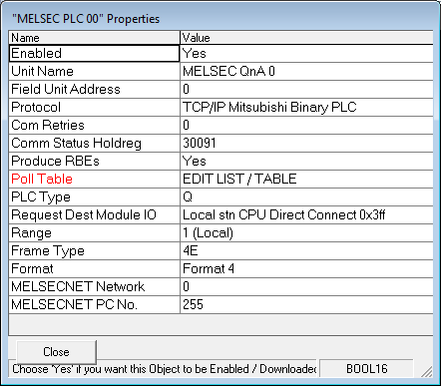
Five different PLC models are available (Q, L, FX, QNA and A) and the 'Q' PLC is the first to be supported.
The 'Request Dest Module IO' has nine options but the first to be implemented is "Local stn CPU Direct Connect 0x3ff".
The protocol can allow for routing messages from PLC to PLC through networks. The Elecsys MELSEC Master will only implement Peer to Peer direct communications (Range 1, Local).
MELSEC has serial, TCP and UDP versions but the MELSEC Master will only implement the TCP (Ethernet) version).
Eight different 'Frame Types' are available (1C to 4C and 1E to 4E) but the MELSEC Master will only implement Frame Types '3E' (without sequence-numbers) and '4E' (with sequence-numbers).
Four message format types are available but the MESLSEC Master will only implement 'Format 4'.
The DEFAULT IP Ports are… 5000 UDP, 5001 TCP.
The RediGate's maximum MELSEC message packet size is 8000 bytes.
Below is a capture of the first five Poll Table Columns with a description of each column.
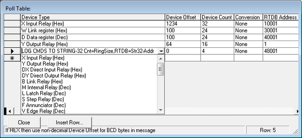
Device Type : This is a list of 27 supported devices and one special Elecsys function to log commands to String-32 registers. The Devices are…
X Input Relay (Hex)
Y Output Relay (Hex)
DX Direct Input Relay (Hex)
DY Direct Output Relay (Hex)
B Link Relay (Hex)
M Internal Relay (Dec)
L Latch Relay (Dec)
S Step Relay (Dec)
F Annunciator (Dec)
V Edge Relay (Dec)
TS Timer Contact (Dec)
TC Timer Coil (Dec)
SS Multi timer contact (Dec)
SC Multi timer coil (Dec)
CS Counter contact (Dec)
CC ounter coil (Dec)
SM Special Relay (Dec)
SB Special link relay (Dec)
D Data register (Dec)
W Link register (Hex)
R File register (Dec)
ZR Expand file reg (Dec)
ER Expand block reg (Dec)
BM E1 Rand access buf (Dec)
TN Timer curr value (Dec)
CN Counter curr value (Dec)
SN Multi timer curr value (Dec)
SD Special register(Dec)
SW Special link reg (Hex)
Z Index register (Dec)
CPU Model x0101,0000
LOG CMDS TO STRING-32 Cnt=RingSize,RTDB=Str32-Addr
Device Offset: This is the offset from the start of the Device Type's buffer. If the Device uses a HEX offset then the Octal BCD value must be entered and if the Device uses a DEC offset then the binary integer value will be copied into the request buffer. This field is a 32 bit integer field and therefore only allows for characters 0 to 9. Some Device Types are normally defined with HEX characters 0 to 9 and A to F. The user must convert the programming address from HEX to a decimal value. For example, if the PLC program uses the Device X-3fff then the 3FF will be converted to a decimal value of 1023.
Device Count: This will limit how many elements of the array will be retrieved from a Poll Reply or it can be used to determine how many Modbus RTDB registers are associated with Write Commands. Writing to structures is not allowed.
Conversion: Currently limited to NONE.
RTDB Address : This column configures the starting RTDB Register address associated with the Device data.
When non-Floating point data is to be stored in the REAL32 area the following rules are used.
- A Single Byte Character value is first converted into the equivalent Floating Point number and then saved as a four byte IEEE value in the RTDB.
- A Two Byte Integer value is converted into the equivalent Floating Point number and then saved as a four byte IEEE value in the RTDB.
- A Character string is packed into four byte segments until no more characters are needed and stored into one or more IEEE RTDB registers.
- A Double float is stored in two separate IEEE RTDB registers.
When non-Int16 data is to be stored in the INT16 area the following rules are used.
- A Single Byte Character value is first converted into the appropriate integer value before being into the RTDB.
- A four byte REGISTER value is saved as three consecutive Integer RTDB registers.
- A Character string is packed into two or four byte segments until no more characters are available and stored into one or more integer RTDB registers.
- A Double float is stored in four separate Int16 RTDB registers or two Int32 registers.
Only Text String data can be stored into the Char-32 registers.
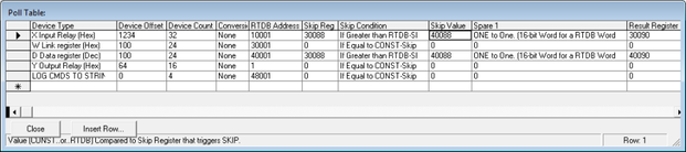
Below are the remaining Poll Table Columns.
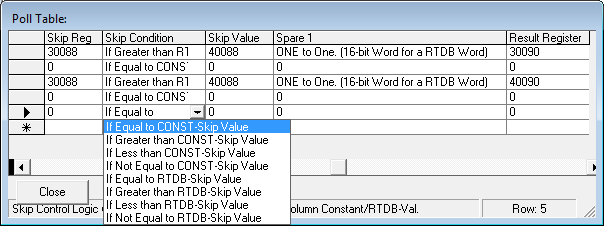
Skip Reg : When this is set to a non-zero value then one or more actions can be applied to the execution of the poll record. Firstly the Poll Record can be skipped when the 'Skip Condition' logic is examined to be TRUE. There are four conditions that can be selected when comparing the 'Skip Reg' value from the RTDB to the 'Skip Value'. The conditions are being Equal to, Greater Than, Less Than or Not Equal to the Skip Value. The 'Skip Value' is either interpreted as a CONSTANT or as a reference to a register in the RTDB area.
Skip Condition : Used in conjunction with the 'Skip Reg' and 'Skip Value'.
Skip Value : This is either used as a verbatim constant value or as a reference to an register in the RTDB area.
Spare 1: To be defined
Result Register : If set to a non-zero value then the number of bytes received from this poll record will be saved to the RTDB.
Tested MELSEC Device Types, R/W:
D (String, Float, DINT, INT), X (Bit), Y (Bit), M (Bit)