RediGate Diagnostics Manual
- Jon Tandy
- Former user (Deleted)

Product Information
Full information about other Elecsys products is available on our website at www.elecsyscorp.com and the RediGate Product Support Page, http://redigate.elecsyscorp.com.
Product Support
Tel: +1-913-890-8905
Fax: +1-913-982-5766
Email: idc-support@elecsyscorp.com
Headquarters, Sales, Support & Manufacturing
Elecsys Corporation
846 N Mart-Way Court
Olathe, KS 66061
Tel: +1-913-647-0158
Fax: +1-913-982-5766
Email: info@elecsyscorp.com
While Elecsys may assist customers with their choice of products, the final choice of product for a specific application is entirely the responsibility of the buyer. Elecsys' entire liability with respect to its products or systems is defined in the Elecsys standard terms and conditions of sale.
Any example code is provided only to illustrate the use of Elecsys products. No warranty, either expressed or implied, is made regarding any example code provided by Elecsys and Elecsys shall incur no liability whatsoever arising from any use made of this code.
Disclaimers
The information in this manual is believed to be accurate at the time of publication. Elecsys Corporation assumes no responsibility for inaccuracies that may be contained in this document and makes no commitment to update or keep current the information contained in this manual. Elecsys Corporation assumes no responsibility for any infringements of patents or other rights of third parties that may result from its use. Elecsys Corporation reserves the right to make changes or improvements to this document and/or product at any time and without notice. While Elecsys may assist customers with their choice of products, the final choice of product for a specific application is entirely the responsibility of the buyer. Elecsys' entire liability with respect to its products or systems is defined in the Elecsys standard terms and conditions of sale.
Any example code is provided only to illustrate the use of Elecsys products. No warranty, either expressed or implied, is made regarding any example code provided by Elecsys and Elecsys shall incur no liability whatsoever arising from any use made of this code.
Electrostatic Discharge (ESD) Protection
These units contain devices that could be damaged by the discharge of static electricity. At all times, please observe industry standard ESD precautions when handling the unit.
![]() WARNING: DO NOT CONNECT OR DISCONNECT CABLES WHEN ENERGIZED, UNLESS POWER HAS BEEN REMOVED FROM THE EQUIPMENT OR THE AREA IS KNOWN TO BE FREE OF IGNITABLE CONCENTRATIONS OF FLAMMABLE SUBSTANCES.
WARNING: DO NOT CONNECT OR DISCONNECT CABLES WHEN ENERGIZED, UNLESS POWER HAS BEEN REMOVED FROM THE EQUIPMENT OR THE AREA IS KNOWN TO BE FREE OF IGNITABLE CONCENTRATIONS OF FLAMMABLE SUBSTANCES.
© 2017 Elecsys Corporation
Table of Contents
Introduction
This manual describes diagnostic capabilities and some troubleshooting information for the RediGate industrial data gateway products, including:
- RediGate MMI user diagnostic menus
- Linux console commands
- UBoot, Bootloader, and startup sequence
The Elecsys gateway products are multi-function communication interface devices, which can be configured for many different types of applications such as protocol conversion, data concentration, and report-by-exception of data. Diagnostics are available to diagnose communication problems and to verify proper operation of every aspect of the system.
Some features described herein may only be available on more recent software releases of the gateway device. Variations between different product models will be distinguished where needed.
Configuration Requirements
This document refers to the gateway configuration or "ACE configuration," which is created and uploaded to the RediGate using the ACE Configuration Editor. See the article Installing ACE and the http://redigate.elecsyscorp.com/manuals/ page for documentation on using ACE to configure the RediGate.
Serial Diagnostics
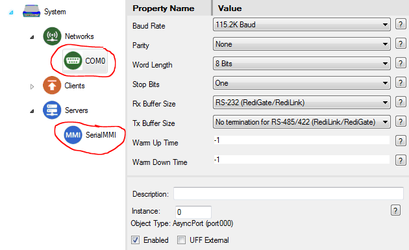
The RediGate typically uses COM0 for a local serial diagnostics port. When the RediGate is powered on, it sends startup messages to its COM0 port. A terminal program must be set up with communication parameters configured for a baud rate of 115,200, no parity, 8 bits, 1 stop bit.
RediGate 100 series: COM0 is available via the Micro-USB port on the front of the device. See the article Installing USB Driver for installing the required USB serial driver in Windows.
RediGate 400 series: COM0 is a DB-9 RS-232 port. Pinout is: pin 3–TX, pin 2–RX, pin 5–GND (use a null modem serial cable to a configuration computer).
In order to use the serial diagnostics (MMI or Linux console) after startup, the following objects are required in the RediGate configuration:
- COM0 (AsyncPort instance 0, under Networks) - Should have 115.2K baud, and -1 for Warm Up and Warm Down Time.
- Serial MMI (under Servers) - Should have COM0 selected for Com Port.
Network Diagnostics
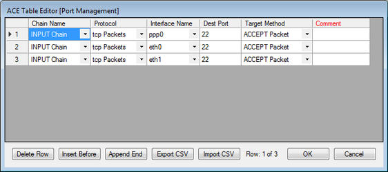
Diagnostics are available through a network connection via a secure shell (SSH) login, typically using IP port 22.
In order to use network diagnostics, the following things are required in the RediGate configuration:
- A RediGate with Ethernet must have an IP address configured to an Ethernet port;
- and/or, the RediGate must have the cellular modem configured, and have an activated cellular account that allows mobile-terminated connections.
(NOTE: Some cellular account activations do not allow SSH connections to be made to cellular device. Check with your account provider for information on this.
- The Firewall configuration must allow a user to make an SSH connection to the RediGate. In the Port Management table, include one or more entries to ACCEPT TCP port 22, such as:
User Accounts
The RediGate has three different user accounts that can be logged into for different purposes.
| User Account | Password | File Transfer | User Menu Login | Linux Command Prompt |
|---|---|---|---|---|
user | user (depends on ACE System object configuration) | COM0 ONLY No file transfer over TCP (SSH) | YES | NO |
| Dirupld | user (depends on ACE System object configuration) | TCP (SSH) ONLY No file transfer over COM0 | NO | Yes (limited permissions) |
| root | (contact Elecsys for default password) | TCP (SSH) ONLY No file transfer over COM0 | NO (but can use 'su user' to start the MMI) | YES COM0 or TCP (SSH) |
User Account: Provides access via a terminal console to the RediGate MMI diagnostic menus, described in this document.
The User account is also needed to load configurations or other files through the COM0 serial port.
The User account is configured in the System object of ACE. The default values for name / password are: user / user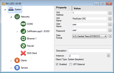
When loading files with the User account, they are stored in the /home/director folder until being installed.NOTE: Do not use the User account when loading files over the network.- Dirupld (file upload) Account: Allows a non-root user to load files to the RediGate over the network.
The Upload account has a username of Dirupld (all lowercase except the first "D", next to last letter is lowercase "L"). The password is the same as the User Account.
When loading files with the Upload account, they are stored in the /home/Dirupld folder until being installed. Root Account: Provides administrative access to the Linux operating system and allows loading configurations or other files over the network.
The Root account is not configured through ACE for security reasons (see the article Changing the Root Password).
The user name is typically root and you can contact Elecsys by email idc-support@elecsyscorp.com for the default root password.
Loading files with the Root account allows files to be stored into either the /home/director or /home/Dirupld folder.NOTE: Do not use the Root or Dirupld accounts when loading files through the serial diagnostics port.
Setting Up Terminal Program
The RediGate diagnostics menu and console are accessed using a terminal program over serial or SSH. There are several terminal programs you can use.
Tera Term: The ACE Configuration Editor (as of version 3.5) includes a built-in option to "Connect to Device." See this article for details: ACE 'Connect to Device' Menu
PuTTY: See these articles for installing and setting up PuTTY:
Setting Up Putty for USB Connection (for RediGate 100 series)
Setting up PuTTY for Serial Communication (for RediGate 400)
Setting up Putty for Network Communication
ExtraPuTTY: Similar to PuTTY, but with additional options such as serial and network file transfer options. Download ExtraPuTTY from http://www.extraputty.com/download.php
Log in to the RediGate using the User account to access the user MMI menus. The following sub-sections describe the diagnostic options for each menu in the user MMI. After logging in to the MMI, the Main Manu is displayed. The current software version (tarball version, 2017-07-24-1300) is shown in the first line of each menu. On the second line is the Unit Name (UnitName), Unit Number (1), and Ethernet 0 IP address (192.3.1.10) which are set in the ACE configuration. The second line also includes the serial number (40170-0118), which is unit-specific. The four menu items under the Main Menu are: Menus are selected by typing the number next to the item and pressing Enter. Pressing Enter at any menu (except the Main Menu) will return to the next higher menu. RediGate User MMI
Main Menu
================ Main Menu ============== ElecSys(V:5.7.2017-07-24-1300) Wed Jul 26 22:20:20 2017 UnitName : 1 @ 192.3.1.10 REDIGATE <40170-0118>-SerialNumb --------------------------------------------- 1) System Services 2) Directory Services 3) Diagnostics Services99 Log OffMake selection:
1- System Services Menu
Main Menu → System Services
The System Services menu is used to restart the system, change the system clock, view the status or enable/disable certain RediGate processes.
Enter 1 at the Main Menu for the System Services menu.
================ System Services ==============ElecSys(V:5.7.2017-07-24-1300) Wed Jul 26 22:47:52 2017UnitName : 1 @ 192.3.1.10 REDIGATE <40170-0118>-SerialNumb---------------------------------------------1) Boot/Reconfigure 2) Set Clock3) Channel Status 4) Channel Enable/Disable5) Channel Scan 6) Single Poll7) RTU Enable/Disable 8) RTU Scan9) RPN Calculator 10) New Master Key11) Read Handshake Pins 12) Write Handshake Pins13) Run Custom Utility 14) MQttClient to Next Broker15) Cell Modem Diags
Make selection:
1- Boot/Reconfigure
Main Menu → System Services → Boot/Reconfigure
Use this option to restart the RediGate or to reconfigure it after loading a new configuration or firmware update (the ACE program's upload menu will automatically reconfigure if the "Deploy immediately" box is checked).
Enter 1 for Boot/Reconfigure, and then either: Y to confirm the reboot, N to cancel, or R to reconfigure. The Reconfigure option stops and restarts the RediGate software, whereas the Reboot option restarts the entire Linux operating system.
If a new configuration and/or firmware file has been loaded to the RediGate, it will be installed when the system restarts.
================ Boot/Reconfigure Director ==============ElecSys(V:5.7.2017-07-24-1300) Wed Jul 26 23:04:38 2017UnitName : 1 @ 192.3.1.10 REDIGATE <40170-0118>-SerialNumb---------------------------------------------
WARNING! Restarting unit will terminate all polling!Non Auto-Start Channels must be individually restarted!Enter 'Y' or 'N' to reboot, or 'R' to reconfigure.
Restart Unit (Y/N/R) ? r
2- Set Clock
Main Menu → System Services → Set Clock
Manually set the RediGate date and time. In systems where the RediGate has NTP (Network Time Protocol) configured, or is connected to an HCP, or is configured to get time through GPS, the clock should be automatically updated, so there is no need to set it through the MMI.
Enter 2 for Set Clock, then enter the new date and time of the system using the following format: MMDDhhmmYYYY.ss where MM=month, DD=day, hh=hour (00 to 23), mm=minute, YYYY=year, and (optional) ss=seconds.
Set Date & Time? (Y/N) yMon Jul 31 11:02:26 UTC 2017
Note: MMDDhhmmYYYY ....includes leading zeros(Examp. New Years Eve of 2015 : 123123592015) :(Examp. Two seconds til 2016 : 123123592015.58) : 073112002017Mon Jul 31 17:00:00 UTC 2017
Write to Hardware clock (Y/N) ? y
Wrote system time to hardware clock
Press ENTER to continue
3- Channel Status (System)
Main Menu → System Services → Channel Status
List status of each Master Channel.
Enter 3 for Channel Status. Enter Y to redisplay or L to view a log of Enable and Disable commands that have been received. Press the Space bar to page through the log.
Channel Status
Chan Name Status Rtus Time==== ============== ======== ==== ==================0 Channel0 w/Errors 1 Mon Jul 31 19:38:20 20172 Master Channel Normal 1 Mon Jul 31 10:56:57 201715 Channel15 Normal 1 Mon Jul 31 10:56:57 2017
Redisplay (Y/N/L where L is Log of Enables/Disables) ? L
Press SPACE to advance through log. Q to QuitMon Jul 31 19:37:52 UTC 2017 Channel-0: EnableMon Jul 31 19:33:32 UTC 2017 Channel-0: Disable
See Channel Status for details on the Master Channel status information.
4- Channel Enable/Disable
Main Menu → System Services → Channel Enable/Disable
Enable or disable all polling on a Master Channel.
Enter 4 for Channel Enable/Disable. Enter the channel number, then either 0 to Disable or 1 to Enable the channel polling.
Channel Enable/Disable
Chan Name              Status    Rtus Time
==== ==============    ========  ==== ==================
   0 Channel0          w/Errors     1  Sun Aug 13 08:06:11 2017
   2 Master Channel    Normal       1  Sun Aug 13 08:03:41 2017
  15 Channel15         Normal       1  Sun Aug 13 08:03:41 2017
Channel 0-15 0
0=Disable 1=Enable ? 0
Channel(0) Disable sent
See Channel Status for details on the Master Channel status information.
When a channel is disabled, it will have a status "Suspended" and its Field Units will typically have the status "Stopped."
================ Rtu Status ==============
ElecSys(V:5.7.2017-08-07-1200)  Sun Aug 13 08:16:05 2017
UnitName : 1 @ 192.3.1.10  REDIGATE  <46247-0004>-SerialNumb
---------------------------------------------
Chan Name              Status    Rtus Time
==== ==============    ========  ==== ==================
   0 Channel0          Suspended    1  Sun Aug 13 08:15:58 2017
   2 Master Channel    Normal       1  Sun Aug 13 08:03:41 2017
  15 Channel15         Normal       1  Sun Aug 13 08:03:41 2017
Enter Channel (0 to 15, -1 for all) ? 0
  -----------------RTU----------------   -----POLL-------  -------ERRORS-------
 Addr Name             Protocol Status     Time     Count  TimOut BadData Frame
----- ---------------- -------- -------- -------- -------- ------ ------- -----
    1 Modbus01         MBMAST00 Stopped  08:15:58        0    656       0    0
5- Channel Scan
Main Menu → System Services → Channel Scan
Trigger one complete scan of a Master Channel, regardless of its enable/disable status or the length of the configured Scan Periods. Scanning the channel will put it back into Enabled mode.
Enter 5 for Channel Scan. Enter the Master Channel number, and Y to trigger the scan.
Channel Scan
Chan Name              Status    Rtus Time
==== ==============    ========  ==== ==================
   0 Channel0          Suspended    1  Sun Aug 13 08:15:58 2017
   2 Master Channel    Normal       1  Sun Aug 13 08:03:41 2017
  15 Channel15         Normal       1  Sun Aug 13 08:03:41 2017
Channel 0-15 0Scan Channel-0 (Y/N) ? yChannel(0) sent scan all
6- Single Poll
Main Menu → System Services → Single Poll
If you have a long poll interval for one or more scans in a Master Channel, use the Single Poll option to execute the scan on demand.
Enter 6 for Single Poll. Enter the Master Channel number, Y if you want to view the Scan Table configuration, and the Index number of the scan to run immediately. The poll will be sent even if the Channel or RTU are disabled.
Single Rtu Poll
Chan Name              Status    Rtus Time
==== ==============    ========  ==== ==================
   0 Channel0          Suspended    1  Sun Aug 13 10:00:02 2017
   2 Master Channel    Normal       1  Sun Aug 13 09:59:02 2017
  15 Channel15         Normal       1  Sun Aug 13 09:59:03 2017
Channel 0-15 0
-----------------RTU---------------- -----POLL------- -------ERRORS-------Addr Name Protocol Status Time Count TimOut BadData Frame----- ---------------- -------- -------- -------- -------- ------ ------- -----1 Modbus01 MBMAST00 No Polls 10:00:03 0 3 0 0Do you want to see the Scan Table? (y/n) y
Index RtuAdr Poll Rate(Sec)0 1 1 36001 1 2 60
Enter Scan Index (0 to 1) 0
Channel(0) sent scan all
7- RTU Enable/Disable
Main Menu → System Services → RTU Enable/Disable
Disable polling of a single Field Unit on a Master Channel.
Enter 7 for RTU Enable/Disable. Enter the Master Channel number and the Field Unit address to disable.
Enabling an RTU does not currently work (as of 8/17/2017). Instead, use RTU Scan or Channel Scan to re-enable the device polling.
Rtu Enable/Disable
Chan Name Status Rtus Time==== ============== ======== ==== ==================0 Channel0 Suspended 1 Sun Aug 13 10:12:25 20172 Master Channel Normal 1 Sun Aug 13 09:59:02 201715 Channel15 Normal 1 Sun Aug 13 09:59:03 2017
Channel 0-15 0
Addr Name Dbg? Protocol Status----- ---------------- ---- -------- ------1 Modbus01 ON MBMAST00 StoppedEnter Rtu to Modify 1
0=Disable, 1=Enable ? 0
Channel(0) sent Rtu00001...Disabled
8- RTU Scan
Main Menu → System Services → RTU Scan
If you have a long poll interval for one or more scans in a Master Channel, you can force all polls to be scanned by selecting the RTU Scan option. This option can also be used to restart polling of an RTU after disabling the Channel or RTU.
Enter 8 for RTU Scan. Enter the Master Channel number and the device address to scan.
Rtu Scan
Chan Name Status Rtus Time==== ============== ======== ==== ==================0 Channel0 Suspended 1 Sun Aug 13 10:06:54 20172 Master Channel Normal 1 Sun Aug 13 09:59:02 201715 Channel15 Normal 1 Sun Aug 13 09:59:03 2017
Channel 0-15 0
Addr Name Dbg? Protocol Status----- ---------------- ---- -------- ------1 Modbus01 ON MBMAST00 StoppedEnter Rtu to Scan 1
Sent Scan RTU 1
9- RPN Calculator
Main Menu → System Services → RPN Calculator
Reverse Polish notation calculator utility allows several simple calculations to be performed within the RediGate menu.
Enter 9 for RPN Calculator. Enter ? at any prompt to redisplay the menu, or Q to quit/exit the calculator.
The Reverse Polish notation calculator operates on numbers entered into a "stack", with the numbers entered first followed by the operator.
Use D to display all current values in the stack, C to clear all values in the stack, E to erase only the last (current) value in the stack.
Addition (+), subtraction (-), multiplication (*), division (/), and power X^Y (P) operate on the two highest numbers in the stack, displaying the result and leaving the result in the next lower stack position.
Modulo (M) divides the previous stack value X by current stack value Y and gives the remainder as an integer in the next lower stack location.
Square root (R), invert 1/X (I), natural log ln (L), inverse log ex (X), and trig functions (T) operate on the highest number in the stack, displaying the result and leaving the result in the current stack position.
Sum (S) all values in the stack (up to 80) and leave the sum in the lowest stack position.
Analysis (A) shows the average value and standard deviation of all values in the stack (leaving current stack values unchanged).
Floating point math (F) converts either from floating point to hexadecimal, or from hexadecimal to floating point. (Note: this operation does not use the RPN stack.)
For example:
- To calculate the value of (3 + 5) / 2, enter: 3 5 + 2 /
The result is a value of 4 in stack location [0].
Value\Operator (+,-,*,/,?,I,L,M,C,Q,D,R,P,S,T,E,A,F,X) Stack>0 3
Stack[0] = 3
Value\Operator (+,-,*,/,?,I,L,M,C,Q,D,R,P,S,T,E,A,F,X) Stack>1 5
Stack[1] = 5
Value\Operator (+,-,*,/,?,I,L,M,C,Q,D,R,P,S,T,E,A,F,X) Stack>2 +
Stack[0] = 8
Value\Operator (+,-,*,/,?,I,L,M,C,Q,D,R,P,S,T,E,A,F,X) Stack>1 2
Stack[1] = 2
Value\Operator (+,-,*,/,?,I,L,M,C,Q,D,R,P,S,T,E,A,F,X) Stack>2 /
Stack[0] = 4
Value\Operator (+,-,*,/,?,I,L,M,C,Q,D,R,P,S,T,E,A,F,X) Stack>1
- To convert a floating point number to hexadecimal, enter F and the number to convert. Enter 0 or 0.0 to exit the floating point calculator.
- To convert a hexadecimal number to floating point, enter F and some non-zero number. Then enter four hexadecimal bytes, most-significant to least-significant.
Value\Operator (+,-,*,/,?,I,L,M,C,Q,D,R,P,S,T,E,A,F,X) Stack>0 f
FLOATING POINT VALUES IN HEX AND VICE VERSA
Enter a Floating point value (0.0 to exit) 2.0
Hex MSB to LSB = 40 0 0 0
Now enter four Hex bytes to dislay in Floating point
Enter MSB first then LSB last Enter Hex Byte 3 40
Enter Hex Byte 2 80
Enter Hex Byte 1 00
Enter Hex Byte 0 00
Floating value = 4
Enter a Floating point value (0.0 to exit)
10- New Master Key
This is a legacy menu which is no longer used in the RediGate.
11- Read Handshake Pins
Main Menu → System Services → Read Handshake Pins
Diagnostic menu to read the current status of RS-232 serial port handshaking inputs (requires configuration and hardware with an RS-232 serial port).
Enter 11 for Read Handshake Pins. Enter the instance number of the serial port, and E if using the Elecsys serial port driver (typical) or L if using the Linux serial driver (normally on COM0).
================ Monitor /dev/acscomm?? handshaking pins ==============ElecSys(V:5.7.2017-07-24-1300) Sun Aug 13 13:00:08 2017UnitName : 1 @ 192.3.1.10 REDIGATE <40170-0118>-SerialNumb---------------------------------------------NOTE:This might require rebooting afterwardsEnter Serial Port Index 1 to 20 (console=0) 2
E=ElecSys driver L=Linux driver eParams=[9600 stop=1 word=8 parenb=0 pareven=0 parstick=0 mode=0 w_up=0 w_down=0]CPU036: 203 SC 20 UART938: 19 SC 22 zeus1655039: 1025 SC 23 pxa2xx-mci41: 0 SC 25 DMA42: 5833 SC 26 ost044: 0 SC 28 Comms Timer Tick85: 16 GPIO 35 bt:dtr103: 0 GPIO 53 mmc card detect131: 1511 GPIO 81 eth0Err: 0
Enter '1' to abort
Com-2 DCD=LOW CTS=LOWCom-2 DCD=LOW CTS=LOWCom-2 DCD=LOW CTS=LOW
The current state of Carrier Detect (DCD) and Clear to Send (CTS) inputs are shown once/second (LOW or HI). Enter 1 to stop the display.
12- Write Handshake Pins
Main Menu → System Services → Write Handshake Pins
Diagnostic menu to enable or disable the handshaking outputs of an RS-232 port (requires configuration and hardware with an RS-232 serial port).
Enter 12 for Write Handshake Pins. Enter the instance number of the serial port, and E if using the Elecsys serial port driver (typical) or L if using the Linux serial driver (normally on COM0).
================ Force /dev/acscomm?? handshaking pins ==============
ElecSys(V:5.7.2017-07-24-1300)  Sun Aug 13 13:09:33 2017
UnitName : 1 @ 192.3.1.10  REDIGATE  <40170-0118>-SerialNumb
---------------------------------------------
NOTE:This might require rebooting afterwards
Enter Serial Port Index 1 to 20 (console=0) 2
E=ElecSys driver L=Linux driver eParams=[9600 stop=1 word=8 parenb=0 pareven=0 parstick=0 mode=0 w_up=0 w_down=0]CPU036: 203 SC 20 UART938: 95 SC 22 zeus1655039: 1025 SC 23 pxa2xx-mci41: 0 SC 25 DMA42: 43630 SC 26 ost044: 0 SC 28 Comms Timer Tick85: 16 GPIO 35 bt:dtr103: 0 GPIO 53 mmc card detect131: 13335 GPIO 81 eth0Err: 0RTS: 0=Low 1=High ? 0Set COM(2) to 0DTR: 0=Low 1=High ? 1Set COM(2) to 1
Enter 1 or 0 to turn ON or OFF the Request to Send (RTS) and Data Terminal Ready (DTR) handshaking outputs.
13- Run Custom Utility
Main Menu → System Services → Run Custom Utility
Custom Utility menu option allows a custom shell script or utility to be run from the user menu. This option requires one or more executable scripts to have previously been loaded onto the RediGate in the /usr/director/bin/ directory, with names beginning "CustUtil" and ending with "_#" (where # is a unique integer up to 32,767).
Enter 13 to select the Run Custom Utility menu. A list of available scripts is displayed. Enter the number of the script following the last _ character.
Make selection: 13
CustUtil_NAT_Menu_5 CustUtil_atest_0CustUtil_Stuff_UFF_4 CustUtil_iptables_1
Enter Index of Custom Utility 0 to N 0
Running CustUtil*_0
*****************Here is a script!*****************
14- MQttClient to Next Broker
Main Menu → System Services → MQttClient to Next Broker
Force an MQTT Client to walk to the next broker IP address.
If only one IP address is configured in the MQ Client (or MQ Client Extra), this will force a disconnect and reconnection to the same broker, along with all initial subscriptions and data publication. Before walking to the next broker IP, you can turn on MQClient diagnostics (Main Menu → Diagnostic Services → Task Diags). Then afterward, check the Monitor Diag's menu to view the MQTT diagnostics during the reconnection.
Enter 14 for MQttClient to Next Broker. If more than one MQ Client is configured, enter 0, 1, or 2 to select which one. Enter Y to force it to the next broker IP address.
================ MQttClient to Next Broker ==============ElecSys(V:5.7.2017-08-07-1200) Thu Aug 17 06:18:54 2017UnitName : 1 @ 192.3.1.10 REDIGATE <46247-0004>-SerialNumb---------------------------------------------0 ==> MQisdp
1 ==> MQisdpX0
Could not find MQisdpX1
Which MQ Client to force? (0 to 1) 0Are you certain you want to force it to the next broker? (y/n) y
Checking connection in 5 seconds. Enter any character to return to MENU
If the connection cannot be made, the last line may be repeated every 5 seconds. To exit, enter any character on the keyboard followed by Enter to return to the previous menu.
15- Cell Modem Diags
Main Menu → System Services → Cell Modem Diags
On a RediGate with built-in cellular modem, perform several diagnostic commands for the cellular modem. This requires not only hardware, but also an active RediGate configuration with the cellular modem configured.
Enter 15 for Cell Modem Diags.
Make selection: 15
================ Cell Modem Diags ==============ElecSys(V:5.7.2017-02-23-1000) Thu Mar 2 18:09:19 2017RediGate400C_CPLX : 1 @ 10.63.192.192 REDIGATE-400 <Use System Serv Option-123>---------------------------------------------Virtual Port Numer73=Diag AT Cmds75=Auto-ATs or NMEA/GPS if HE-91077=NMEA/GPS if DE-91079=CellLEDsor 0 to Exit? 73
Enter 73 or 75 for the virtual port number on which to view diagnostics (one or more of these should be configured in ACE).
After this, the RediGate will automatically request several AT commands from the modem to retrieve status and activation information.
The command outputs are described with comments below.
Sending AT+GMMReceived[15]-> HE910 OKThis is the modem model (HE910 for GSM/HSPA, or DE910-DUAL for CDMA).
Sending AT+CNUMReceived[37]-> +CNUM: "","19132109122",129 OKThis is the phone number associated with the account activation.
Sending AT#CCIDReceived[37]-> #CCID: 89014104277578463113 OKFor the HE910 modem, this is the SIM card number. For the DE910-DUAL, this command will return an error.
Sending AT+CGDCONT?Received[42]-> +CGDCONT: 1,"IP","i2gold","",0,0 OKFor the HE910 modem, the second item in double quotes is the APN of the cellular access point. If the SIM is not properly installed or the RediGate is improperly configured, having an incorrect APN will block cellular connections.
Sending AT#MEIDESN?Received[9]-> #MEIDESN: A1000032B304F6,000000000000,00000000For the DE-910-DUAL modem, this is the MEID number. For the HE910, this command will return an error.
Sending AT#CIMIReceived[32]-> #CIMI: 310410757846311 OKThis is the IMSI number.
Sending AT#CGSNReceived[32]-> #CGSN: 357164042289457 OKFor the HE910 modem, this is the IMEI number. For the DE910-DUAL modem, this is the MEID number, split with a comma.
Sending AT+CREG?Received[20]-> +CREG: 0,1 OKThis is the mode and connection status. The first number should normally be 0 (disable unsolicited).
The second number indicates registration status: 0=not registered, 1=registered/home network, 2=searching, 3=denied, 5=registered/roamingFor Telit modem:
Sending AT$GPSACP
Received[30]-> $GPSACP: 214127.000,3853.5898,N,09447.4488,W,0.9,315.4,3,12.1,7.3,3.9,310715,07
UTC time (hhmmss.sss)
Latitude (ddmm.mmmm N/S)
Longitude(dddmm.mmmm E/W)
HDOP, Altitude (meters), Fix (0=invalid, 2=2D fix, 3=3D fix)
Course over ground (degrees), Speed over ground (Km/hr), Speed over ground (knots)
Date of fix (ddmmyy), Number of satellites in use
For Quectel modem:
TX-> at+qgpsgnmea="rmc"
RX-> +QGPSGNMEA: $GPRMC,213806.00,A,3853.585246,N,09447.491297,W,3.9,0.0,131020,2.2,E,A*23
This is the GPS data, if a GPS antenna is connected to the modem. Otherwise, it will mostly be just commas with no data. GPS data represents:
UTC time (hhmmss.sss). A=active, V=void
Latitude (ddmm.mmmm N/S)
Longitude(dddmm.mmmm E/W)
Speed over ground (knots), Track angle (degrees)
Date of fix (ddmmyy), Magnetic variation (E/W), checksum data
Sending AT+CSQReceived[40]-> +CSQ: 28,3 OKTo convert latitude/longitude to decimal degrees, use dd + (mm.mmmm/60), as dd.dddd (negative for S or W).
To convert to degree/minute/second, multiply fractional (.mmmm*60)=ss.ss for seconds, as dd° mm' ss.ss".
The first number after +CSQ is the signal strength. 99=no signal, 0-31 indicates increasing strength (0 = -113 dBm, 31 = -51 dBm, in steps of 2 dBm per CSQ number).
The second number is the bit error rate (BER). 0=best, 7=worst.
Repeat? (y/n) n
Then press Enter to exit the modem diagnostics, or A/ to repeat the last command (AT+CSQ, signal strength).
Or enter an 'AT' modem string to manually send a command to the modem.
Enter AT Command (Enter to Exit, 'A/' repeats last, 'A//' repeat every 2 secs) a//Press Q<enter> to quit repeatingSending[8]-> AT+CSQReceived[20]-> +CSQ: 28,2 OKPress Q<enter> to quit repeatingSending[8]-> AT+CSQReceived[20]-> +CSQ: 29,2 OK
Enter 'q' to stop the repeating AT+CSQ commands. And 'Enter' again to exit the menu.
Enter AT Command (Enter to Exit, 'A/' repeats last, 'A//' repeat every 2 secs)q
2- Directory Services Menu
Main Menu → Directory Services
The Directory Services menu is used for various file operations within the RediGate file system.
Enter 2 at the Main Menu for the Directory Services menu.
================ Directory Services ==============ElecSys(V:5.7.2017-08-07-1200) Thu Aug 17 06:32:10 2017
UnitName : 1 @ 192.3.1.10 REDIGATE <46247-0004>-SerialNumb
---------------------------------------------
1) Executables 2) Current Configs
3) Download Directory 4) Put File to Remote
5) Get File From Remote 6) Rename File
7) Delete File in Remote 8) Delete IsaGraf Files
9) View Zombie.log 10) IsaGraf App Info
11) Restore Previous UFF 12) View UFF Processing Details
13) View Load-Store File 14) View kernel or message logs
15) MQtt XML Information 16) View customer settings
17) ZMODEM File to Remote 18) ZMODEM File from Remote
19) View Problem.txt 20) View ModemLog.txt
21) Store-N-Forward File
Make selection:
1- Executables
Main Menu → Directory Services → Executables
View list of files contained in the /usr/director/bin folder, mainly executable files.
Enter 1 for Executables. File sizes are rounded to 1Kb; thus some entries listed as zero are not actually empty files.
Make selection: 1
================ Executable Directory ==============ElecSys(V:5.7.2017-08-07-1200) Thu Aug 17 08:23:01 2017UnitName : 1 @ 192.3.1.10 REDIGATE <46247-0004>-SerialNumb---------------------------------------------12 ArClock* 72 IButton* 100 TeleGyrMast*0 ArFunc.so@ 4 IsaFind_1st.sh* 72 Term1Serv*0 ArFunc.so.1@ 12 IsagInfo* 72 TermServd*60 ArFunc.so.1.7* 84 JSON_Rbe* 24 UdpHandler*8 ArcomUpdate.sh* 8 LinuxSys.sh* 52 UdpServ*336 BACnetIpMast* 60 MELSECMast* 8 UffUpdate.txt336 BACnetIpSlave* 4 MMI* 268 VirtMast*
2- Current Configs
Main Menu → Directory Services → Current Configs
Show diagnostic information related to the current configuration files in the RediGate.
When an XML configuration is uploaded to the RediGate, it is converted into a UFF file (or the UFF file may be loaded from ACE directly). The configuration is then broken into various components and stored in the /usr/director/configs folder.
Enter 2 to show Current Configs. Enter Y to see additional information about the current configuration.
The first two parts of the display show the current UFF filename and the internal component configurations stored in the RediGate.
================ Configuration Directory ==============
ElecSys(V:5.7.2017-08-07-1200)  Thu Aug 17 08:28:07 2017
UnitName : 1 @ 192.3.1.10  REDIGATE  <46247-0004>-SerialNumb
---------------------------------------------
Contents of /usr/director/config
-rw-r--r--    1 root     director     12347 Aug 17 06:17 /usr/director/config/RG-110E.uff
Show RediGate Linux Config Files (Y/N) y
/usr/director/config/Channel00.1.cfg
/usr/director/config/Channel02.1.cfg
/usr/director/config/Channel15.1.cfg
/usr/director/config/DiagManual_Configuration.xml.gz
/usr/director/config/Director.0.cfg
/usr/director/config/IsaGraf02.1.cfg
/usr/director/config/Launch.conf
/usr/director/config/MQRbePr.1.cfg
/usr/director/config/MQXRbePr0.1.cfg
/usr/director/config/MQisdp.1.cfg
/usr/director/config/MQisdpX0.1.cfg
/usr/director/config/ModSlTcp00d.7.cfg
/usr/director/config/ONE_BAD_POLL.txt
/usr/director/config/RG-110E.uff
/usr/director/config/TS32.txt
/usr/director/config/Watchdog.1.cfg
/usr/director/config/css.000
/usr/director/config/customer
/usr/director/config/findfirst
/usr/director/config/uff2lnux.dbg
/usr/director/config/watchdog
/usr/director/config/Channel00:DBM.1.cfg ModMast00002.1.cfg Tags00001.1.cfg Tags00002.1.pubLaunch.conf ModMast00003.1.cfg Tags00001.1.pub Tags00003.1.cfgModMast00001.1.cfg SCAN.1.cfg Tags00002.1.cfg Tags00003.1.pub/usr/director/config/Channel02:DBM.1.cfg Launch.conf ModMast00001.1.cfg SCAN.1.cfg/usr/director/config/Channel15:DBM.1.cfg SCAN.1.cfgLaunch.conf VirtMast00003.1.cfg/usr/director/config/init.arcom:IsaPlc02.sh gateway inittab.Port0 inittabMMI-grepS89runIO200port hosts.modname inittab.Port2 networksSerialMMI.sh hosts.modsh inittab.Port64eth0 inittab-modmmi inittab.Port65eth0_1 inittab-no-mgetty inittab.Port79
Do you want to debug the UFF file? (Y/N) ? y
If you have entered Y for the two prompts, you will then be given the uff2lnux diagnostic, which shows in detail the ACE objects and property values contained in the current configuration.
At the next four prompts, press Enter. The following output is typical of what might be seen in a configuration diagnostic view.
Just keep pressing ENTER until finished...
==========================
uff2lnuxRevision $Revision: 1.91 $
Usageuff2lnux -> Program will prompt youuff2lnux -f * -> Read *.UFF filesuff2lnux -f Apex -a 1 -> Read Apex.UFF, Abbreviated reportuff2lnux -f * -p -> Read *.UFF files, Pause after each objectuff2lnux -f Apex -N -> No Bootloader files createduff2lnux -f * > text -> NOTE: use the MS-DOS redirect symbol '>' toredirect the output to a text fileuff2lnux -c plus any cmd -> Create individual download files
Enter UFF file name without UFF extension (wildcards ok)APEX 08/17/117 08:28:21==========================
Pause after each Object Entry? y/ny 08/17/117 08:28:22==========================Create Individual Download Files? y/nN==========================Abbreviated Report? (Mostly Network Info) y/nNNo Leading minus sign!117 08:28:23
Customer: RediGate
COM3_STOP_ECHO=1ALL_16550_COMM=1DF1_NEWPOLLTBL=1RTU_FORCE_SCANUPD=1DF1_DUPLEX_CTRL=1EXTRA_TSERV_SOCKS=1DO_PPP_OPTIONS=1BAD_POLL_KILLS_RTU=1BLOB_ANY_ADDR=1HCP_32BIT_AWARE=1POST_XML_FILE=1TIME_STAMP_32BIT=1UDHCPD_SERVER=1HCP_RTC_VIA_SYSCMD=1COMPILE_POD=1DF1_BIN_POLLS=1SRTP_NOT_ENRON_MAP=1MULTI_HOME_SCRIPT=1EXTRA_RBE_FLAGS=1HTTP_PUT_NOT_POST=1LINUX_3_XX=1OPC_RELAX_RBE=1FALCON_PROJECT=1MSEC_TIMESTAMP=1REDIGATE_PROJECT=1PPP_CMUX_PTDEV=1DIRUPLD_PASSWD=1DELAY_HLTHECHO=1BASH_USES_TILDE=1=================================================================
Opening APEX...
In this section, some important information is given about the configuration file, including:
- XML filename (if applicable, truncated to 32 characters) or UFF filename (if loaded directly from ACE ??? check this)
- Configuration date (date of the XML to UFF translation on a RediGate, or the date of original creation if UFF was loaded directly from ACE)
- Build number of the configuration (updated every time the configuration is saved)
UffVer=3 (DiagManual_Configuration.xml) 17/08/21 14:00:0CfgVer=[1] BuildNumber=16 Machine=/ElecsysRediGate/Number of Object Entries=40 : Size=12347
Each following section includes the object "filename" separated by @@, which appears in the ACE Configuration Editor after the Object Type, and all of the properties included in the UFF configuration file. The file size includes the total number of "bytes" included in the property values for the object. Enter Q to exit the configuration diagnostic, B followed by a number to back up that many sections, S followed by a number to skip forward that many sections, or any other key to show the next section.
@@cir0000@@ 8 bytes @ 1080Circuit Type: DIRECTPrimary Port: 64Secondary : -1Redundancy : Dedicated; Press Any Key. Q to quit. S to skip 'N' Entries. B to Backup. [35 remain]
@@cir0001@@ 25 bytes @ 1088Circuit Type: MASTER NETWORK(s)Server Port : 3040ConnectDelay: 15 secondsServer IP : 192.003.001.011Interface : Ether0= Press Any Key. Q to quit. S to skip 'N' Entries. B to Backup. [34 remain]
@@firewall@@ 299 bytes @ 1268
Input Policy : DROPOutput Policy : ACCEPTForward Policy : ACCEPTPort Management Chain : INPUT tcp eth0 22 ACCEPTPort Management Chain : INPUT tcp eth0 3040 ACCEPT
<<< RAW CUSTOM IPTABLES>>>
iptables -A INPUT -p icmp -m state --state NEW,ESTABLISHED,RELATED -j ACCEPTiptables -A OUTPUT -p icmp -m state --state NEW,ESTABLISHED,RELATED -j ACCEPT: Press Any Key. Q to quit. S to skip 'N' Entries. B to Backup. [33 remain]
@@lxsystem@@ 155 bytes @ 1567Apex Number : 1Apex Name : UnitNameUser Name : userPassword : userDate Enumer : 5< Press Any Key. Q to quit. S to skip 'N' Entries. B to Backup. [32 remain]
@@mastchan00@@ 71 bytes @ 1722Name : Channel0Type : 993Auto Start : YesTimeout : 200 msecBroadcast : 0 msec delayInterpoll : 0 msec delayScan Period : 7000 secNet Recover : 0 sec
RTU Poll Delay(sec)===== ====== ==========1 1 36001 2 602 1 36002 2 603 1 36003 2 60-------------
; Press Any Key. Q to quit. S to skip 'N' Entries. B to Backup. [35 remain]
3- Download Directory
Main Menu → Directory Services → Download Directory
Enter 3 for to show the files contained in the /home/director download directory.
Files with a ".run" extension are shortcuts to the current configuration files, and after the arrow (->) is the actual location of the file. If there is an .xml.gz or .uff file without the .run extension, it indicates a configuration file that has been loaded but not deployed. (See Configuration Not Updating on RediGate for fixing a problem if there is more than one un-deployed configuration file.)
=============== Download Directory ==============ElecSys(V:5.7.2017-07-24-1300) Mon Aug 14 11:54:25 2017UnitName : 1 @ 192.3.1.10 REDIGATE <40170-0118>-SerialNumb---------------------------------------------total 8-rw-r--r-- 1 root root 64 Aug 13 12:59 AceConfigName.txt-rw-r--r-- 1 root root 6 Jul 23 2014 CoreMSQIDlrwxrwxrwx 1 root root 53 Aug 13 12:59 DiagManual_Configuration2.xml.gz.run -> /usr/director/config/DiagManual_Configuration2.xml.gzlrwxrwxrwx 1 root root 32 Aug 13 12:59 RG-110E.uff.run -> /usr/director/config/RG-110E.uff-rw-r--r-- 1 root root 0 Aug 13 12:59 UnitName.namlrwxrwxrwx 1 root root 28 Aug 13 12:59 is15000000.run -> /usr/director/bin/is15000000
Press ENTER to continue
4- Put File to Remote
Main Menu → Directory Services → Put File to Remote
Load a file to the RediGate through the COM0 console port using YMODEM protocol. (This option requires using a terminal program that supports the YMODEM file transfer protocol.)
Enter 4 for Put File to Remote. After selecting the menu, a series of "C" characters will be displayed for 40 seconds.
In the serial terminal program, select the option to send a file using YMODEM protocol.
- In Tera Term or ExtraPUTTY, select File Transfer → YMODEM → Send
- In HyperTerminal, select Transfer → Send File, and select the YMODEM protocol
YMODEM timeout
After the transfer is complete, the file will be in the /home/director folder. Use Directory Services option 3 to view contents of the Download Directory.
Make selection: 4
================ Put File to Remote ==============ElecSys(V:5.7.2017-08-07-1200) Thu Aug 17 13:33:54 2017UnitName : 1 @ 192.3.1.10 REDIGATE <46247-0004>-SerialNumb---------------------------------------------Ready to receive file.../dev/ymodem.dbg=-1STARTINGCCPress ENTER to continue
5- Get File From Remote
Main Menu → Directory Services → Get File From Remote
Retrieve a file from the RediGate's /home/director folder through the COM0 console port using YMODEM protocol. (This option requires using a terminal program that supports the YMODEM file transfer protocol.)
Enter 5 for Get File From Remote. Enter the exact file name to retrieve (case-sensitive). If the filename is not entered, it will time out in 40 seconds.
If you download a ".run" file (which is a shortcut to an actual file), it will download the original file, but you will need to rename in Windows to remove the ".run" extension.
Make selection:5
================ Get File from Remote ==============ElecSys(V:5.7.2017-08-07-1200) Thu Aug 17 14:57:01 2017UnitName : 1 @ 192.3.1.10 REDIGATE <46247-0004>-SerialNumb---------------------------------------------total 172-rw-r--r-- 1 root root 63 Aug 17 09:51 AceConfigName.txt-rw-r--r-- 1 root root 6 Jul 23 2014 CoreMSQID-rw-r--r-- 1 user director 73421 Aug 17 13:34 DefaultTemplate.xml.tmp.gzlrwxrwxrwx 1 root root 52 Aug 17 09:55 DiagManual_Configuration.xml.gz.run -> /usr/director/config/DiagManual_Configuration.xml.gzlrwxrwxrwx 1 root root 32 Aug 17 09:55 RG-110E.uff.run -> /usr/director/config/RG-110E.uff-rw-r--r-- 1 root root 0 Aug 17 09:55 UnitName.namlrwxrwxrwx 1 root root 28 Aug 13 12:59 is15000000.run -> /usr/director/bin/is15000000-rw-r--r-- 1 root root 166 Dec 4 1999 ppp0.log
Enter name if File to Receive DiagManual_Configuration.xml.gz.run/dev/ymodem.dbg=-1AceConfigName.txt RG-110E.uff.run@CoreMSQID UnitName.namDefaultTemplate.xml.tmp.gz is15000000.run@DiagManual_Configuration.xml.gz.run@ ppp0.log
Press ENTER to continue
6- Rename File
Main Menu → Directory Services → Rename File
Enter 6 to rename a file in the /home/director folder. Enter the exact existing and new filenames (case-sensitive).
7- Delete File in Remote
Main Menu → Directory Services → Delete File in Remote
Enter 7 to delete a file in the /home/director folder. Enter the exact existing filename (case-sensitive) to be deleted.
Make selection: 7
================ Delete File ==============ElecSys(V:5.7.2017-08-07-1200) Thu Aug 17 17:38:58 2017UnitName : 1 @ 192.3.1.10 REDIGATE <46247-0004>-SerialNumb---------------------------------------------AceConfigName.txt RG-110E.uff.runCoreMSQID UnitName.namDiagManual_Configuration.xml.tmp.gz.run is15000000.runNewConfiguration.xml.gz ppp0.logThere is no need to delete a file ending in '.run' or '.nam'These are only softlinks to the actual running files.Enter File Name to delete NewConfiguration.xml.gz
Press ENTER-rw-r--r-- 1 root root 63 Aug 17 09:51 /home/director/AceConfigName.txt-rw-r--r-- 1 root root 6 Jul 23 2014 /home/director/CoreMSQIDlrwxrwxrwx 1 root root 52 Aug 17 09:55 /home/director/DiagManual_Configuration.xml.tmp.gz.run -> /usr/director/config/DiagManual_Configuration.xml.gzlrwxrwxrwx 1 root root 32 Aug 17 09:55 /home/director/RG-110E.uff.run -> /usr/director/config/RG-110E.uff-rw-r--r-- 1 root root 0 Aug 17 09:55 /home/director/UnitName.namlrwxrwxrwx 1 root root 28 Aug 13 12:59 is15000000.run -> /usr/director/bin/is15000000
-rw-r--r-- 1 root root 166 Dec 4 1999 /home/director/ppp0.log
8- Delete IsaGraf Files
Main Menu → Directory Services → Delete IsaGraf Files
Enter 8 to remove an ISaGRAF logic file (such as is15000000) from the /usr/director/bin folder.
Make selection: 8
================ Delete IsaGraf Files ==============ElecSys(V:5.7.2017-08-07-1200) Thu Aug 17 17:52:33 2017UnitName : 1 @ 192.3.1.10 REDIGATE <46247-0004>-SerialNumb----------------------------------------------rw-r--r-- 1 root director 88972 Aug 17 13:41 is15000000
Enter File Name to delete is15000000
9- View Zombie.log
Main Menu → Directory Services → View Zombie.log
Enter 9 to view the Zombie.log file, if it exists.The Zombie.log file is created in /home/director if a RediGate process dies unexpectedly (Linux calls this a "Zombie" process). Certain diagnostic information is stored in the file, and then shortly afterward the RediGate will automatically reboot. The hope is that if the process died as the result of a one-time anomaly, the system will automatically recover itself.
When no Zombie.log file exists and a process dies, the RediGate will reboot relatively quickly (within a minute). If the Zombie.log file exists when the event occurs, such as a persistent condition (bad configuration setting, etc.), the reboot will be delayed longer (up to 9-10 minutes) to allow a technician to intervene, obtain log files from the RediGate, reconfigure it, etc., in order to remove the condition causing the Zombie process to occur.
Press the Space bar to page through to the end of the file. Newest entries are at the bottom. The Zombie.log shows the process name (which process died) and the date/time and other system conditions when it was detected.The Zombie.log file is never deleted automatically, but it can be deleted manually through the Delete File in Remote option, or through the command line or an FTP deletion.
Make selection: 9
Press SPACE BAR for more pages...Fri Aug 18 07:53:07 CDT 2017Discovered [Z [DirectorScan]] zombie 17123Active Internet connections (servers and established)Proto Recv-Q Send-Q Local Address Foreign Address Statetcp 0 0 0.0.0.0:ssh 0.0.0.0:* LISTENtcp 0 0 localhost:1883 0.0.0.0:* LISTENtcp 0 0 0.0.0.0:3040 0.0.0.0:* LISTENtcp 1 0 UnitName:42636 192.3.1.11:3040 CLOSE_WAITtcp 0 0 :::ssh :::* LISTENActive UNIX domain sockets (servers and established)Proto RefCnt Flags Type State I-Node Pathunix 20 [ ] DGRAM 2934 /dev/logunix 2 [ ] DGRAM 115113unix 2 [ ] DGRAM 16168unix 2 [ ] DGRAM 115115
10- IsaGraf App Info
Main Menu → Directory Services → IsaGraf App Info
Enter 10 to show information about any ISaGRAF logic files that may exist on this RediGate. This shows the ISaGRAF filename, project name and build number.
Note that the ISaGRAF logic file is not automatically operational just because of being resident on a RediGate. In order to use ISaGRAF, the configuration must also include a Virtual Circuit and ISaGRAF Field Unit configured under an Internal Channel with an instance number that matches the first two digits of the ISaGRAF filename (e.g., Internal Channel 15 for the example below).
Make selection: 10
================ IsaGraf App Info ==============ElecSys(V:5.7.2017-08-07-1200) Thu Aug 17 17:50:39 2017UnitName : 1 @ 192.3.1.10 REDIGATE <46247-0004>-SerialNumb---------------------------------------------
FileName=is15000000 -> IsaGraf-Project=wdpub06 : Version=251
Press ENTER...
11- Restore Previous UFF
Main Menu → Directory Services → Restore Previous UFF
Enter 11 to restore the previous RediGate configuration. The RediGate keeps only one previous backup configuration that was running before the current configuration. This menu option allows the system to be reverted back to the previous.
After being prompted, enter Y to confirm rolling back the configuration (with an automatic reconfigure and possibly reboot if needed), or N or Enter to keep the current.
Make selection: 11
================ Restore Previous UFF Configuration ==============
ElecSys(V:5.7.2017-08-07-1200)  Fri Aug 18 14:17:58 2017
UnitName : 1 @ 192.3.1.10  REDIGATE  <46247-0004>-SerialNumb
---------------------------------------------
-rw-r--r--    1 root     director      5450 Aug 17 09:51 /usr/director/backup/DiagManual_Configuration.xml.gz
-rw-r--r--    1 root     director     12347 Aug 17 09:51 /usr/director/backup/RG-110E.uff
Do you want to RESTORE with REBOOT this UFF or XML file? (y/n) y
12- View UFF Processing Details
Main Menu → Directory Services → View UFF Processing Details
Enter 12 to view details of the RediGate's processing of the UFF configuration file. Press Enter to begin viewing the details.
When a .uff file is loaded directly, or created from an .xml.gz configuration file, the RediGate processes the UFF file in order to start up all its processes. The UFF Processing Details give some detailed diagnostic information about how the new configuration was handled. The following lines show some excerpts from a typical diagnostic output.
Make selection: 12
================ View UFF Processing Details ==============ElecSys(V:5.7.2017-08-07-1200) Fri Aug 18 14:21:59 2017UnitName : 1 @ 192.3.1.10 REDIGATE <46247-0004>-SerialNumb---------------------------------------------Press the SPACE bar to view the next page or ENTER to advance one line
Rtdb 0 has 4 Fields 96 bytesRtdb 0 has 4 Fields 96 bytesRtdb 1 has 4 Fields 96 bytesRtdb 0 has 0 Fields 0 bytesRtdb 0 has 5 Fields 120 bytesCustomer is RediGateBuild Directory is .Director System V-1.001Comm Port V-1.001
Ethernet V-1.001Rx_Tx_SerialComm00 232 0Rx_Tx_SerialComm02 232 0Rx_Tx_SerialComm64 232 0Rx_Tx_SerialComm65 232 0Rx_Tx_SerialComm79 4095 4095Found Primary COM64 for Circuit0000Found Primary COM79 for Circuit0200Found 3 Master ChannelsBuilding Chann00 (Channel0)Match Chann-Rtu (Modbus02) Addr=2Match Chann-Rtu (Modbus01) Addr=1Match Chann-Rtu (Modbus03) Addr=3MQttClientPort=1883Count of RtuRBE=16DELAY_HLTHECHO=1REDIGATE_400=1CCM2_NOT_ENRON_MAP=1BASH_USES_TILDE=1
Finished... Press ENTER
13- View Load-Store File
Main Menu → Directory Services → View Load-Store File
Enter 13 to view the contents of a LoadStore file, and (if present) enter the name of the file to view.
The LoadStore object is used as part of an ISaGRAF logic program, with default values that may be configured in the LoadStore child object under the ISaGRAF Field Unit. Values in the LoadStore file are stored in permanent memory in /usr/director/bin (e.g. ls02000000 in the example below). Values may be updated during runtime of the ISaGRAF program. The LoadStore file contains 16 columns by a variable number of rows ("Boards"). The View Load-Store File option shows the data one row (16 integer values) at a time. Press Enter to continue displaying each row, or Esc Enter to quit.
Make selection: 13
================ Display Load/Store File ==============ElecSys(V:5.7.2017-08-07-1200) Fri Aug 18 16:27:52 2017UnitName : 1 @ 192.3.1.10 REDIGATE <46247-0004>-SerialNumb----------------------------------------------rw-r--r-- 1 root director 64 Aug 18 14:32 ls02000000
Enter Isagraf LS File to display ls02000000Load-Store Board 10 : 0x00000001 11 : 0x00000002 22 : 0x00000003 33 : 0x00000004 44 : 0x00000005 55 : 0x00000006 66 : 0x00000007 77 : 0x00000008 88 : 0x00000009 99 : 0x0000000a 1010 : 0x00000000 011 : 0x00000000 012 : 0x00000000 013 : 0x00000000 014 : 0x00000000 015 : 0x00000000 0Press ENTER to Continue : ESC to quit
14- View kernel or message logs
Main Menu → Directory Services → View kernel or message logs
Enter 14 to view the Linux log files, then enter 1 for the 'kernel' log or 2 for the 'message' log.
Press the Space bar to page through the log file until the end, or Enter to scroll one line at a time.
Make selection: 14
================ View KERNEL or MESSAGE Logs ==============ElecSys(V:5.7.2017-08-07-1200) Sun Aug 27 16:14:04 2017UnitName : 1 @ 192.3.1.10 REDIGATE <46247-0004>-SerialNumb---------------------------------------------1=/var/log/kernel 2=/var/log/messageEnter 1 or 2 2
Press SPACE BAR to advance screen....Q to Quit
15- MQtt XML Information
Option 15 on the Directory Services menu is a legacy option that is not used for most customers.
16- View customer settings
Main Menu → Directory Services → View customer settings
Enter 16 to view the settings contained in the "customer file." The first line contains the customer or product name, such as "RediGate_400". On the RediGate 100 or 400 products, these settings will typically be identical according to the standard tarball (firmware) release. (On some systems, the customer settings may contain some alternative values that enable various processes to act in a different, customer-specific manner.)
Make selection: 16
================ View CUSTOMER settings ==============ElecSys(V:5.7.2017-08-24-1000) Fri Dec 3 23:02:54 1999DNPMastTest : 1 @ 10.63.191.28 REDIGATE-400 <38258-0025>-SerialNumb---------------------------------------------Press the SPACE bar to view the next page or ENTER to advance one lineRediGate_400RTU_CMD_STATS=0RTU_PASS_STATS=0RBE_ALL_DATA=1
* * *
Finished... Press ENTER
17- ZMODEM File to Remote
Main Menu → Directory Services → ZMODEM File to Remote
Load a file to the RediGate through the COM0 console port using ZMODEM protocol. (This option requires using a terminal program that supports the ZMODEM file transfer protocol.)
Enter 17 for ZMODEM File to Remote. After selecting the menu, a series of characters will be displayed for 2 minutes and 40 seconds.
In the serial terminal program, select the option to send a file using ZMODEM protocol.
- In Tera Term or ExtraPUTTY, select File Transfer → ZMODEM → Send
- In HyperTerminal, select Transfer → Send File, and select the ZMODEM protocol
ZMODEM Transfer
After the transfer is complete, the file will be in the /home/director folder. Use Directory Services option 3 to view contents of the Download Directory.
Make selection: 17
================ ZMODEM Put File to Remote ==============ElecSys(V:5.7.2016-05-02-1600) Sat Dec 18 10:13:44 1999PoT-Field-Device : 1 @ 192.3.1.10 REDIGATE-400 <45743-0002>-SerialNumb---------------------------------------------
Ready to receive file...Press ENTER to continue
18- ZMODEM File from Remote
Main Menu → Directory Services → ZMODEM File from Remote
Retrieve a file from the RediGate's /home/director folder through the COM0 console port using ZMODEM protocol. (This option requires using a terminal program that supports the ZMODEM file transfer protocol.)
Enter 18 for ZMODEM File From Remote. Enter the exact file name to retrieve (case-sensitive). If the filename is not entered, it will time out in a minute and 40 seconds.
Depending on the serial terminal program, you may have to start the ZMODEM file receive through a menu option.
19- View Problem.txt
Main Menu → Directory Services → View Problem.txt
View Problem.txt file in /home/director download directory, if it exists. The Problem.txt file is created if there was a problem during a reconfiguration or software update, such as loading two different configuration files or loading the wrong tarball type (RG-100 vs. RG-400 series).
Enter 19 for View Problem.txt. If there is a file present, its contents will be shown. The file is cumulative (until deleted manually), so it may indicate multiple failed update attempts.
Make selection: 19
Press 'Q' to quit, SPACE-BAR for next page
Sun Aug 27 15:44:48 CDT 2017
Multiple .xml.gz files cannot be translatedtest1.xml.gz and test2.xml.gz
Sun Aug 27 15:51:25 CDT 2017/home/director/2017-08-07-1200-redigate_7_3.15_32.tar.gz was not tagged for REDIGATEPress ENTER...
20- View ModemLog.txt
Main Menu → Directory Services → View ModemLog.txt
View the modemlog.txt file in /tmp/ if it exists. The modemlog.txt file contains the AT command history of the RediGate's modem initialization sequence. This can be useful if there are problems in the cellular modem connections.
Enter 20 for View ModemLog.txt. If there is a file, its contents will be shown. This file is cumulative, so it may indicate multiple cellular connections, starting with a timestamp and the contents of the modem configuration. The file exists in a RAM drive which will be cleared on unit reboot.
Make selection: 20
Press 'Q' to quit, SPACE-BAR for next pageMUX is not configured yet... exitingSat Sep 10 01:09:39 EST 2016
* * *
Setting CM_APN to i2goldSetting CM_PeerDNS to YESSetting CM_Authenticate to NONESetting CM_UserName to userSetting CM_Password to pass-----------------------------------------------------------------------killall: pppd: no process killedkillall: cellmodem.tcl: no process killed→ATE0V1...OK←OK→AT+CSQ...OK
<-+CSQ: 16,99\r\n\r\nOK→AT#CGSN...OK
<-#CGSN: 270113182611766277\r\n\r\nOK→AT#CIMI...OK
<-#CIMI: 310005133228549\r\n\r\nOK→AT#SELINT=2...OK←OK→ATI3...OK←Telit\r\n\r\nOK→AT+CGMM...OK
<-DE910-DUAL\r\n\r\nOKModem type: DE910-DUAL->AT E0 V1 Q0...OK←OK→AT+CNUM...OK
<-+CNUM: "",5136096212,129\r\n\r\nOKPhone #: (513) 609-6212→AT+IPR=230400...OK
<-OK
* * *
(The Local IP address indicates a successful connection and the RediGate's address on the cellular network.)→AT+CSQ...OK
<-+CSQ: 13,99\r\n\r\nOK→ATDT#777...CONNECT←CONNECT
Running pppd /dev/ttyEMUX0 230400 file /dev/null modem crtscts lock asyncmap 0 nodetach nodefaultroute noauth usepeerdnsUsing interface ppp0Connect: ppp0 <--> /dev/ttyEMUX0local IP address 75.242.97.94
remote IP address 66.174.62.1primary DNS address 198.224.147.135secondary DNS address 198.224.146.119Press ENTER...
21- Store-N-Forward File
Main Menu → Directory Services → Store-N-Forward
View the stored contents of a "Store and Forward" data log file. This feature depends on having Store & Forward configured in the RediGate and having a file containing stored historical data.
Enter 21 for Store-N-Forward File.
Enter 0 for the /tmp/sdcard1 device (this will normally be the built-in SD memory card. If a memory card is not present, this device will be in a RAM drive).
Enter the folder containing Store & Forward data. Folders are named "SNFxx_yyyyy", where xx is the Master Channel number, and yyyyy is the Field Unit address (such as SNF15_00001).
Then enter the file name of the data to view. Data is stored in .csv files, one for each device and for each day on which historical data was stored. The filename is case-sensitive and must be entered exactly.
Make selection: 21
================ Store and Forward Files ==============ElecSys(V:5.7.2017-08-24-1000) Wed Sep 6 16:35:43 2017RediGate120E : 1 @ 0.0.0.0 REDIGATE <46247-0002>-SerialNumb---------------------------------------------0=/tmp/sdcard1 : 1=/tmp/usb1 : 2=Edit Last Reported Times
Select folder (0,1)? 0
Enter0to select the /tmp/sdcard1 location, then enter the folder name containing the archive files.
Gateway.json SNF14_00003 SNF15_00003 SNF_HELP.txtSNF00_00001 SNF15_00002 SNF15_00004Enter Directory name (e.g. SNF00_00001) SNF00_00001-rwxr-xr-x 1 root root 241 Oct 4 2016 CHAN00~RTU-1~20161004.csv-rwxr-xr-x 1 root root 16021 Oct 6 2016 CHAN00~RTU-1~20161006.csv-rwxr-xr-x 1 root root 428984 May 22 20:35 CHAN00~RTU-1~20170522.csv
Enter name if File to View CHAN00~RTU-1~20170522.csv
After entering the file name, the file will be displayed one page at a time. Press the Space bar to page through the file, or enter Q to quit the display.
Comma-separated values are shown, following a CSV header. The header columns are:
- EpochTime is the timestamp of data in seconds since 1/1/1970 (32-bit integer, based on the system clock at the time); or if the Pacing is set to 0, the column will be EpochTimeMS (a 64-bit integer containing milliseconds since 1/1/1970).
- RegAddr_OR_TagName is either the RTDB register number, or the Tag name if configured for that register.
- Delivered is 1 if the data has already been published to MQTT, or 0 if not published.
- GoodQuality is 1 is the point quality status at the time it was logged (1=online, 0=offline).
- DataType is the type enumeration of the register (1=Boolean, 2=CHAR, 3=UINT8, 4=SINT16, 5=UINT16, 8=SINT32, 9=UINT32, 10=REAL32, 11=STRING-32, 12=STRING-256, 15=REAL64, 16=SINT64, 17=UINT64).
- Value is the register value at the time it was logged. String data might include commas, which would appear as additional CSV columns.
Below is an example of the content of the CSV file containing historical values using EpochTime (seconds).
- The data header is stored in the CSV file every time the connection goes from connected to disconnected state.
- This example shows tag names CycleCount, TankLevel, and PumpStatus, and an untagged register address 40001.
- The Delivered column is 1=Published or 0=Unpublished. (This value is only saved at the time the data originally stored and is not updated once the historical data is subsequently published.)
- The GoodQuality column indicates the Quality flag of the RTDB register at the time it was stored.
- The DataType column is 1=Boolean, 5=UINT16, 9=UINT32, 10=REAL32.
- The Value column shows the value in the data type. Boolean values are 0 or 1.
EpochTime,RegAddr_OR_TagName,Delivered,GoodQuality,DataType,Value1495429200,CycleCount,1,1,9,9107227331495429214,40001,1,1,5,655351495429220,TankLevel,1,1,10,4.01495429224,CycleCount,0,1,9,9107292181495429229,CycleCount,0,1,9,9107313781495429235,PumpStatus,0,1,1,1
Below is an example with the content of the CSV file containing historical value using EpochTimeMS (milliseconds).
EpochTimeMS,RegAddr_OR_TagName,Delivered,GoodQuality,DataType,Value1529675863415,40001,0,1,8,15296758631529675863415,40002,0,1,8,367
The Store & Forward process keeps track of the date of the last-reported historical record value. Upon reconnected link status of the monitored process, it will begin at this timestamp to publish additional historical values.
You can change the last-reported time to skip forward and not publish some records, or to skip backward and republish older historical records.
From the Directory Services menu option 21, select 2 to Edit Last Reported Times.
Make selection: 21
================ Store and Forward Files ==============ElecSys(V:5.7.2017-08-24-1000) Wed Sep 6 16:35:43 2017RediGate120E : 1 @ 0.0.0.0 REDIGATE <46247-0002>-SerialNumb---------------------------------------------0=/tmp/sdcard1 : 1=/tmp/usb1 : 2=Edit Last Reported Times
Select folder (0,1 or 2)? 2
Enter the Channel Number and Field Unit Address of a unit to change the Store & Forward last-reported date/time.
Chan Name              Status    Rtus Time
==== ==============    ========  ==== ==================
   0 CHAN00            Normal       2  Mon Jul 23 12:27:10 2018
   2 Master Channel    Normal       1  Thu Jul 19 15:16:14 2018
Enter Channel Number (0-15) 0
-----------------RTU---------------- -----POLL------- -------ERRORS-------Addr Name Protocol Status Time Count TimOut BadData Frame----- ---------------- -------- -------- -------- -------- ------ ------- -----1 RTU-1 SOSMST00 PollDone 12:27:14 57304 0 0 0Enter Rtu Address (0 - 65535) 1
Enter a number of days (positive or negative) to adjust the current last-reported time for this Field Unit. Enter a whole number of days, or a fraction (such as -0.5 to skip backward half a day, or 0.04167 to skip forward one hour).
Enter Y to accept the adjusted last-reported time.
Last CSV Time ==>  2018-10-28 12:00:04  LOCAL
DAYs forward (positive) or backward (negative) to adjust (e.g. 0.5 days) 0.04167
New CSV Time ===>  2018-10-28 13:00:04  LOCAL
Is this acceptable as the new reporting time? (y/n) y
3- Diagnostics Services Menu
Main Menu → Diagnostics Services
The Diagnostics Services menu provides real-time diagnostics about various network and protocol processes running in the RediGate. Options are provided to help diagnose system problems, communication errors, view data obtained from field devices, etc.
Enter 3 at the Main Menu for the Directory Services menu.
================ Diagnostic Services ==============ElecSys(V:5.7.2017-08-24-1000) Wed Sep 6 19:31:54 2017RediGate120E : 1 @ 0.0.0.0 REDIGATE <46247-0002>-SerialNumb---------------------------------------------1) System Status 2) Network Interfaces3) Run Time and Loading 4) System Resources5) Task Status 6) Task Diags7) Channel Status 8) Channel Diags9) Rtu Status 10) Rtu Diags11) Rtu Clear 12) Slave Diags13) IP Route Table 14) Ping Service15) RTDB Status 16) RTDB Diags17) MQtt Status 18) RTDB Data Dump19) Dial Backup 510) Trend a Point535) View Custom Rpt99) Monitor Diag's
Make selection:
Debug Levels
Menu options 6, 8, 10, 12, and 16 are used to enable or disable various RediGate task diagnostics to a certain level of detail. Use option 99 (Monitor Diagnostics) to view the real-time activity based on the task diagnostic levels that have been set. If a certain event in the system occurs which is at or below the current Debug Level for that task, the message will appear in the diagnostics display. Menu option 5 shows the current list of Debug Level for all tasks.
Following is a description of the diagnostic Debug Levels:
- 0 = Fatal Errors – This is the least detailed type of debugging that can be selected. Such an event is fatal to system operation, effectively ending task operation.
- 1 = General Errors – These are operational or system errors that are not fatal in nature.
- 2 = Status Messages – (default) These are informational messages which describe important task status changes, etc.
- 3 = Data Displays – Somewhat more detailed display of protocol message headers or system events.
- 4 = Data Dumps – This is the most detailed level of diagnostic logging. All events relating to the system task are displayed in Monitor Diagnostics when this option is selected. For some tasks, this includes hex dumps of bytes sent or received.
1- System Status
Main Menu → Diagnostics Services → System Status
View certain system condition of the RediGate operating code, including the Linux build information and current message queues.
Enter 1 for the System Status menu, and press Enter through the following sets of information.
The Message Queues include message queue ID, owner and permissions of the task, and the number of used bytes and messages. For most users, this information is low-level and not too useful, but occasionally it can be informative of problems if one task is taking up a growing number of used bytes, or if the list of message queues continues to grow longer.
Make selection: 1
================ System Status ==============
ElecSys(V:5.7.2017-08-07-1200)  Sun Sep  3 21:17:07 2017
UnitName : 1 @ 192.3.1.10  REDIGATE  <46247-0004>-SerialNumb
---------------------------------------------
Linux UnitName 3.15.10-00073-ge03f088 #0 PREEMPT Thu Nov 20 10:42:18 CST 2014 armv5tel GNU/Linux
Press ENTER to continue
------ Message Queues --------
key        msqid      owner      perms      used-bytes   messages
0x00000290 0          root       666        0            0
0x00002dc8 1409025    user       666        0            0
0x00000bed 720899     root       666        0            0
0x00000bf2 753668     root       666        0            0
0x00000bf6 786437     root       666        0            0
0x00000bfa 819206     root       666        0            0
0x00000bff 851975     root       666        0            0
0x00000c05 884744     root       666        0            0
0x00000c06 917513     root       666        0            0
0x00000c07 950282     root       666        0            0
0x00000c09 983051     root       666        0            0
0x00000c0c 1015820    root       666        0            0
0x00000c0e 1048589    root       666        0            0
0x00000c0f 1081358    root       666        0            0
0x00000c10 1114127    root       666        0            0
0x00000c12 1146896    root       666        0            0
0x00000c14 1179665    root       666        0            0
0x00000c16 1212434    root       666        0            0
0x00000c18 1245203    root       666        0            0
0x00000c19 1277972    root       666        0            0
0x00000c5f 1376277    root       666        0            0
0x00000c1a 1310742    root       666        0            0
0x00000c1b 1343511    root       666        0            0
Press ENTER to continue
2- Network Interfaces
Main Menu → Diagnostics Services → Network Interfaces
View IP addresses of network interfaces and socket status information (Linux commands ifconfig and netstat).
Enter 2 for Network Interfaces, then enter Y to view the socket statuses.
Make selection: 2
================ Network Interfaces ==============ElecSys(V:5.7.2017-08-07-1200) Sun Sep 3 21:17:07 2017
UnitName : 1 @ 192.3.1.10 REDIGATE <46247-0004>-SerialNumb---------------------------------------------eth0 Link encap:Ethernet HWaddr 82:49:22:2B:82:A6inet addr:10.63.191.28 Bcast:10.63.255.255 Mask:255.255.0.0inet6 addr: fe80::8049:22ff:fe2b:82a6/64 Scope:LinkUP BROADCAST RUNNING MULTICAST MTU:1500 Metric:1RX packets:19565659 errors:0 dropped:83411 overruns:0 frame:0TX packets:77491 errors:0 dropped:0 overruns:0 carrier:0collisions:0 txqueuelen:0RX bytes:1376149850 (1.2 GiB) TX bytes:6030078 (5.7 MiB)
lo Link encap:Local Loopbackinet addr:127.0.0.1 Mask:255.0.0.0inet6 addr: ::1/128 Scope:HostUP LOOPBACK RUNNING MTU:65536 Metric:1RX packets:412 errors:0 dropped:0 overruns:0 frame:0TX packets:412 errors:0 dropped:0 overruns:0 carrier:0collisions:0 txqueuelen:0RX bytes:37684 (36.8 KiB) TX bytes:37684 (36.8 KiB)
ppp0 Link encap:Point-to-Point Protocol
inet addr:10.12.0.15 P-t-P:10.12.0.15 Mask:255.255.255.255
UP POINTOPOINT RUNNING NOARP MULTICAST MTU:1500 Metric:1
RX packets:11 errors:0 dropped:0 overruns:0 frame:0
TX packets:5 errors:0 dropped:0 overruns:0 carrier:0
collisions:0 txqueuelen:3
RX bytes:424 (424.0 B) TX bytes:61 (61.0 B)Do you want to see Socket Statuses (Y/N) ? y
Press SPACE to page forward...Active Internet connections (servers and established)Proto Recv-Q Send-Q Local Address Foreign Address Statetcp 0 0 0.0.0.0:22 0.0.0.0:* LISTENtcp 0 0 10.63.191.28:22 10.242.3.2:65199 ESTABLISHEDtcp 0 0 :::22 :::* LISTENActive UNIX domain sockets (servers and established)Proto RefCnt Flags Type State I-Node Pathunix 14 [ ] DGRAM 2214 /dev/log
Press ENTER to continue...
3- Run Time and Loading
Main Menu → Diagnostics Services – Run Time and Loading
View the amount of time the Linux system has been running (in days and hours:minutes) and the state of processor loading (Linux command uptime).
Enter 3 for Run Time and Loading.
Make selection: 3
================ Run Time ==============ElecSys(V:5.7.2017-08-07-1200) Sun Sep 3 21:17:07 2017
UnitName : 1 @ 192.3.1.10 REDIGATE <46247-0004>-SerialNumb---------------------------------------------
Local_Time Up_Time 0.0=IDLE => 1 min 5 min 15 min <= 1.00=BUSY---------- ------- ----- ----- ------18:47:04 up 11 days, 12:47, load average: 2.89, 3.35, 3.43
Press ENTER to continue
4- System Resources
Main Menu → Diagnostics Services → System Resources
View the amount of RAM and Flash memory that is used and free (Linux commands free and df).
Enter 4 for System Resources.
Make selection: 4
================ System Resources ==============ElecSys(V:5.7.2017-08-07-1200) Sun Sep 3 21:17:07 2017
UnitName : 1 @ 192.3.1.10 REDIGATE <46247-0004>-SerialNumb---------------------------------------------
System RAM (1k-blocks)total used free shared buffersMem: 253988 23296 230692 0 0-/+ buffers: 23296 230692Swap: 0 0 0
System FLASH
Filesystem 1K-blocks Used Available Use% Mounted onubi0:rootfs 57476 22804 34672 40% /devtmpfs 126872 0 126872 0% /devtmpfs 126992 0 126992 0% /dev/shmtmpfs 126992 152 126840 0% /tmp
Press ENTER to continue
5- Task Status
Main Menu → Diagnostics Services → Task Status
View the Debug Level for all running processes in the RediGate code. The Debug Level is used for RediGate task logging and can be set using menu option 6 and others. Real-time diagnostics can be viewed using menu option 99 - Monitor Diagnostics.
Enter 5 for Task Status.
The tasks are numbered sequentially (referred to as "slot numbers"), starting from 0. The name following each task is the mnemonic that appears in the real-time view as events occur.
The word following the task name (Status, Display, Dump, etc.) indicates the current Debug Level of the task (see Debug Levels).
Tasks are marked with All, None, or Some, to indicate whether debugging is enabled/disabled for all or part of the units associated with that task.
Make selection: 5
================ Task Status ==============ElecSys(V:5.7.2017-08-07-1200) Sun Sep 3 21:17:07 2017
UnitName : 1 @ 192.3.1.10 REDIGATE <46247-0004>-SerialNumb---------------------------------------------13 PROCESSES
0 - WATCHDOG Status ( All) 7 - CH01XDBM Status ( All)1 - CHANNL00 Status ( All) 8 - DNPMST01 Status ( All)2 - CHANNL01 Status ( All) 9 - CHN01SCN Status ( All)3 - CHANNL15 Status ( All) 10 - CH15XDBM Status ( All)4 - CH00XDBM Status ( All) 11 - VIRTMS15 Status ( All)5 - DNPMST00 Status ( All) 12 - CHN15SCN Status ( All)6 - CHN00SCN Status ( All)Redisplay (Y/N)?
6- Task Diags
Main Menu → Diagnostics Services → Task Diags
Set the Debug Level for a process. (You can also set Debug Levels by using option 8 for Master Channel diagnostics, 10 for Field Unit protocol diagnostics, 12 for Slave Channel diagnostics, or 16 for RTDB diagnostics.) Use option 99 - Monitor Diagnostics to observe the real-time diagnostics of each task after setting the Debug Levels.
Enter 6 for Task Diags.
Make selection: 6
================ Task Diagnostics ==============ElecSys(V:5.7.2017-08-07-1200) Sun Sep 3 21:17:07 2017
UnitName : 1 @ 192.3.1.10 REDIGATE <46247-0004>-SerialNumb---------------------------------------------13 PROCESSES
0 - WATCHDOG Status ( All) 7 - CH01XDBM Status ( All)1 - CHANNL00 Status ( All) 8 - DNPMST01 Status ( All)2 - CHANNL01 Status ( All) 9 - CHN01SCN Status ( All)3 - CHANNL15 Status ( All) 10 - CH15XDBM Status ( All)4 - CH00XDBM Status ( All) 11 - VIRTMS15 Status ( All)5 - DNPMST00 Status ( All) 12 - CHN15SCN Status ( All)6 - CHN00SCN Status ( All)Task Slot Number (0 to 12) ?5
First, enter the Task Slot Number from the numbers that are listed. Depending on the task you have selected, you will have to enter a number of other information, starting with the new Debug Level that you wish to enable. NOTE: The Debug Level is GLOBAL for this task; i.e., it applies to all units (Node Addresses) associated with this task. If you wish to enable debugging for only one (or more) Field Unit or Node Address on a task, see NOTE below for Enable/Disable.
Task DNPMST00 Status ( All)
Valid Debug Level:0 - Fatal Errors (Ending)1 - General Errors (Error)2 - Status Messages (Status)3 - Data Display (Display)4 - Data Dump (Dump)
Debug Level 0-4 or 'S'tats ?4
If prompted, enter a Node Address within the task to which the diagnostics status will be applied. For master protocol tasks, this will be the Field Unit Address of the device being monitored. For other task types, other information will be prompted to identify the scope of the diagnostic level being applied.
Enter Node Address for Slot=5 (-1 for all) 1
If prompted, enter 1 to enable the diagnostics for the task, or 0 to disable diagnostics for the Node Address (or All).
Enter 0=Disable : 1=Enable [Default=1] ? 1
Enable/Disable
NOTE: If a task controls multiple Node Addresses (such as Field Units), diagnostics for each Node Address can be enabled or disabled separately. One or more units may have debugging enabled simultaneously—enabling diagnostics for a single unit does not automatically disable diagnostics for all the others.
For instance, to enable diagnostics for only 3 out of 10 Field Units on a master channel, first Disable diagnostics for "All" units; then select the Task Diagnostics menu multiple times to Enable diagnostics for only certain Field Unit node addresses. The last Debug Level selected applies to ALL enabled units controlled by this task.
After entering all information related to the task Debug Level modification, a single line output will indicate the change in status, and the list of tasks will generally be shown again.
Setting DNPMST00 to Level Dump
13 PROCESSES
0 - WATCHDOG Status ( All) 7 - CH01XDBM Status ( All)1 - CHANNL00 Status ( All) 8 - DNPMST01 Status ( All)2 - CHANNL01 Status ( All) 9 - CHN01SCN Status ( All)3 - CHANNL15 Status ( All) 10 - CH15XDBM Status ( All)4 - CH00XDBM Status ( All) 11 - VIRTMS15 Status ( All)5 - DNPMST00 Dump ( All) 12 - CHN15SCN Status ( All)6 - CHN00SCN Status ( All)Task Slot Number (0 to 12)?
Once you have modified the Debug level for all tasks that you wish to change, press Enter to return to the Diagnostics Services menu.
7- Channel Status
Main Menu → Diagnostics Services → Channel Status
View the status of Master Channels.
Enter 7 for Channel Status. If any Master Channels or Internal Channels are configured in the RediGate, the following information is displayed:
- Master Channel number from configuration
- Master Channel name from configuration
- Current channel status (see Master Channel Status Indications for a list of status values)
- Number of Field Units (RTUs) configured on the channel
- System timestamp of the last event on the channel.
Make selection: 7
================ Channel Status ==============ElecSys(V:5.7.2017-08-07-1200) Sun Sep 3 21:17:07 2017
UnitName : 1 @ 192.3.1.10 REDIGATE <46247-0004>-SerialNumb---------------------------------------------Chan Name Status Rtus Time==== ============== ======== ==== ==================0 Channel0 w/Errors 1 Sat Dec 11 19:34:32 19991 Channel1 w/Errors 1 Sat Dec 11 19:34:33 199915 Channel15 Normal 1 Tue Nov 30 06:00:02 1999
Redislay (Y/N/D where D is Debug List)?
If you enter 'D' for Debug List, an additional list of FieldUnit statuses will be shown:
- FieldUnit Address from configuration
- FieldUnit Name from configuration
- Status of debugging (enabled or disabled) for the FieldUnit
- Protocol enumeration as it appears in the Task List
- Status (see RTU Status for a list of these indications)
Redislay (Y/N/D where D is Debug List) ? d
Enter a Channel Number (0 to 15) ? 0
Addr Name Dbg? Protocol Status----- ---------------- ---- -------- ------1 DNP3 Field Unit ON DNPMST00 TimeoutPress ENTER
Master Channel Status Indications
Values for the Master Channel status are:
- Good - Channel is enabled and received response from the last field device polled.
- No Polls - No polls are being sent. This may indicate that the Channel has been disabled, all Field Units are disabled, or no polls are configured
- w/Error - The channel has received an error sometime since the last time the Channel status was requested. This error may have happened a long time in the past, but if there are no further errors, the next refresh of the Channel status should show Good.
- Fatal Er - A fatal error has occurred, which has disabled the operation of the channel.
8- Channel Diags
Main Menu → Diagnostics Services → Channel Diags
Set the Debug Level for one or more Master Channels. Use option 99 to monitor live diagnostics after setting the Debug Level.
Enter 8 for Channel Diags. Enter the number of the Master Channel or Internal Channel for the FieldUnit that you want to change Debug Level. (See Master Channel Status Indications for a list of status values.)
Make selection: 8
================ Channel Diags ==============ElecSys(V:5.7.2017-08-07-1200) Sun Sep 3 21:17:07 2017
UnitName : 1 @ 192.3.1.10 REDIGATE <46247-0004>-SerialNumb---------------------------------------------Chan Name Status Rtus Time==== ============== ======== ==== ==================0 Channel0 w/Errors 1 Tue Dec 14 09:37:32 19991 Channel0 w/Errors 1 Tue Dec 14 09:37:31 199915 Channel15 Normal 1 Tue Nov 30 06:00:02 1999
Enter Channel (0 to 15) ?0
Enter the new Debug Level that you wish to enable for this FieldUnit.
Valid Debug Level:0 - Fatal Errors (Ending)1 - General Errors (Error)2 - Status Messages (Status)3 - Data Display (Display)4 - Data Dump (Dump)
Debug Level 0-4 ?4
Enter the FieldUnit Address to which the diagnostics status will be applied, or -1 to apply this change to all FieldUnits on the channel.
Enter 1 to enable the diagnostics for the FieldUnit, or 0 to disable diagnostics.
Addr Name Dbg? Protocol Status----- ---------------- ---- -------- ------1 DNP3 Field Unit ON DNPMST00 Timeout
Enter RTU Address (-1 for all) ? 1
Enter 0=Disable : 1=Enable [Default=1] ?1
After entering all information related to the task Debug Level modification, a single line output will indicate the change in status, and the list of tasks will generally be shown again.
Setting Scan-Rtu 1 to Enable Dump
================ Channel Diags ==============ElecSys(V:5.7.2017-08-07-1200) Sun Sep 3 21:17:07 2017
UnitName : 1 @ 192.3.1.10 REDIGATE <46247-0004>-SerialNumb---------------------------------------------Chan Name Status Rtus Time==== ============== ======== ==== ==================0 Channel0 w/Errors 1 Tue Dec 14 09:37:57 19991 Channel0 w/Errors 1 Tue Dec 14 09:37:56 199915 Channel15 Normal 1 Tue Nov 30 06:00:02 1999
Enter Channel (0 to 15)?
Once you have modified the Debug level for all FieldUnits that you wish to change, press Enter to return to the Diagnostics Services menu, or enter another channel number.
9- RTU Status
Main Menu → Diagnostics Services → RTU Status
List diagnostic information about Circuits and Field Units under a Master Channel.
Enter 9 for RTU Status. Enter the Master Channel number to view Channel, Circuit, and Field Unit status. Or enter -1 to view the status for units on all channels.
(See Master Channel Status Indications for a list of status values.)
================ Rtu Status ==============
ElecSys(V:5.7.2017-08-07-1200)  Mon Aug 14 02:10:12 2017
UnitName : 1 @ 192.3.1.10  REDIGATE  <46247-0004>-SerialNumb
---------------------------------------------
Chan Name              Status    Rtus Time
==== ==============    ========  ==== ==================
   0 Channel0          Normal       3  Mon Aug 14 02:10:07 2017
   2 Master Channel    w/Errors     1  Mon Aug 14 02:02:14 2017
  15 Channel15         Normal       1  Mon Aug 14 02:02:14 2017
Enter Channel (0 to 15, -1 for all) ? 0
  -----------------RTU----------------   -----POLL-------  -------ERRORS-------
 Addr Name             Protocol Status     Time     Count  TimOut BadData Frame
----- ---------------- -------- -------- -------- -------- ------ ------- -----
    1 Modbus01         MBMAST00 PollDone 02:10:07        9      2       0    0
    2 Modbus02         MBMAST00 Timeout  02:09:15        0      9       0    0
    3 Modbus03         MBMAST00 Polling  02:09:15        7      2       0    0
Redisplay (Y/N/E where E is Extended Info)?
See Channel Status for details on the Master Channel status information.
All configured Field Units are listed with status, one per line.
- Addr – FieldUnit address from configuration
- Name – FieldUnit name from configuration
- Protocol – Enumeration indicating both the protocol and Master Channel instance number. For example, MBMAST00 refers to Modbus Master protocol on Channel 0. The Protocol enumeration is also used for diagnostic messages in the Monitor Diagnostics log.
- Status – Current state of each Field Unit.
- PollDone - Device is in communication and last poll was completed successfully.
- Timeout - Last poll to device timed out with no valid response.
- BadData - Last poll received some data but it was not a correct expected response (including an exception code).
- FrameErr - Last poll received a framing error (possibly part of the message was received but not all – ?? check with John)
- Stopped - Field Unit or Channel is disabled or not being polled
- Polling - Poll has been sent but response not yet received, or a response to one poll has been received but not all polls are completed, so the device status cannot be completely confirmed yet.
- No Polls - No polls have been sent to Field Unit since last restart.
- Time – Last time the Field Unit was accessed (started, polled, command sent).
- Count – Number of polls which have successfully received a response.
- TimOut – Number of polls which have timed out after all configured retries.
- BadData – Number of polls which have received a bad data response.
- Frame – Number of polls which have received a framing error response.
If the Extended Info option is select by entering E, more information is displayed showing the configuration of the various port configurations (Async or Network Circuit).
Redisplay (Y/N/E where E is Extended Info) ? e
Attempts_Per_PollAdd Unit Dbg Circuit Last Clear Boot Type Port----- -------------- --- ------- ---- ----- ---- ----- ----1 Modbus01 ON CONNECT 1 1.0 1.0 TCP/IP 192.3.1.11:30402 Modbus02 ON CONNECT 4 4.0 4.0 DIRECT COM02 19200 NONE3 Modbus03 ON CONNECT 1 1.0 1.0 TCP/IP 192.3.1.11:3040Press ENTER...
The Address and Field Unit name are the same as above. Other circuit information is given for each device.
- Dbg – ON or OFF depending on whether debugging is enabled or disabled for this unit.
- Circuit – CONNECT if the configured serial port can be connected to successfully, or DISCONNECT if the port cannot be accessed.
- Last – Number of poll attempts on the last poll to either receive a response or time out.
- Clear – Average number of poll attempts per poll since the poll counters were last cleared.
- Boot – Average number of poll attempts per poll since last reboot.
- Type – DIRECT for a serial connection or TCP/IP for a network circuit.
- Port – For serial ports, indicate the comm port number, baud rate, and parity (NONE, FULL for hardware handshaking, or TIME for timed RTS handshaking). For TCP/IP ports, indicate the IPaddress:port of the network circuit.
10- RTU Diags
Main Menu → Diagnostics Services → RTU Diags
Set the Debug Level for diagnostic monitoring of Master Channel protocol messages to a Field Unit. Use option 99 to monitor live diagnostics after setting the Debug Level.
Enter 10 for RTU Diags. Enter the number of the Master Channel or Internal Channel for the FieldUnit that you want to change Debug Level.
(See Master Channel Status Indications for a list of status values.)
Make selection: 10
================ Rtu Diags ==============
ElecSys(V:5.7.2017-08-07-1200) Mon Aug 14 02:10:12 2017UnitName : 1 @ 192.3.1.10 REDIGATE <46247-0004>-SerialNumb---------------------------------------------Chan Name Status Rtus Time==== ============== ======== ==== ==================0 Channel0 Normal 3 Mon Aug 14 02:10:07 20172 Master Channel w/Errors 1 Mon Aug 14 02:02:14 201715 Channel15 Normal 1 Mon Aug 14 02:02:14 2017
Enter Channel (0 to 15, -1 for all) ?0
Enter the new Debug Level that you wish to set for Field Units on this Channel.
NOTE: the Debug Level applies to all Field Units of the same protocol under this Master Channel. (To see diagnostics for only some Field Units on a channel, you must disable diagnostics on the other units.)
Valid Debug Level:0 - Fatal Errors (Ending)1 - General Errors (Error)2 - Status Messages (Status)3 - Data Display (Display)4 - Data Dump (Dump)
Debug Level 0-4 ?4
Enter the FieldUnit Address to enable at the above diagnostics level, or -1 for all FieldUnits on the channel.
Enter 1 to enable the diagnostics for the FieldUnit(s), or 0 to disable diagnostics.
Enter RTU Address (-1 for all) ? 1
Enter 0=Disable : 1=Enable [Default=1] ?1
After entering all information related to the task Debug Level modification, a single line output will indicate the change in status, and the list of tasks will generally be shown again.
Setting Prot-Rtu 1 to Enable Dump
Valid Debug Level:0 - Fatal Errors (Ending)1 - General Errors (Error)2 - Status Messages (Status)3 - Data Display (Display)4 - Data Dump (Dump)
Debug Level 0-4?
Once you have modified the Debug level for all FieldUnits on this channel that you wish to change, press Enter to return to the Diagnostics Services menu.
11- Rtu Clear
Main Menu → Diagnostics Services → RTU Clear
Clear polling statistics for a Field Unit, or all Field Units on a Master Channel.
Enter 11 for Rtu Clear. Enter the Master Channel number, and either clear statistics all devices or enter the unit address to clear.
Make selection: 11
================ Rtu Clear ==============ElecSys(V:5.7.2017-08-24-1000) Mon Dec 6 05:15:36 1999DNPMastTest : 1 @ 10.63.191.28 REDIGATE-400 <38258-0025>-SerialNumb---------------------------------------------Chan Name Status Rtus Time==== ============== ======== ==== ==================0 Channel0 Normal 1 Mon Dec 6 05:15:33 19991 Channel0 Normal 1 Mon Dec 6 05:15:34 199915 Channel15 Normal 1 Tue Nov 30 06:00:02 1999
Enter Channel (0 to 15) ? 0
Clear All Rtus (Y/N) ? n
-----------------RTU---------------- -----POLL------- -------ERRORS-------Addr Name Protocol Status Time Count TimOut BadData Frame----- ---------------- -------- -------- -------- -------- ------ ------- -----1 DNP3 Field Unit DNPMST00 PollDone 05:15:39 111713 30 0 0Enter Rtu to Clear ? 1
Clearing Rtu 1 Status Counters
Clear All Rtus (Y/N)?
12- Slave Diags
Main Menu → Diagnostics Services → Slave Diags
Set the Debug Level for a Slave Channel, or view statistics on a Slave Channel.
Enter 12 for Slave Diags. Enter the enumeration, starting from 0, for the Slave Channel you wish to view or set.
Slave Channels are identified with a short name plus the numeric instance number of the task. Network Slave Channels may either end with a 'd' (for the listening socket) or a number (for an active socket connection). Examples:
- DNPSLAV0 = DNP Async Slave Channel, instance number 0
- MBNSL00d = Modbus Network Slave Channel 'daemon' (listening socket), instance number 0. This is the task that waits for incoming connections, and then spawns a separate task handling the active socket connection. If you set the Debug Level for this task, then any future connections to the socket will inherit the same Debug Level.
- MBNSL001 = Modbus Network Slave Channel (active socket connection #1), instance number 0. Many device protocol servers allow multiple simultaneous sockets to the same port. If you set the Debug Level for this task, it only applies to the current host connection to the socket. Once the socket connection is closed, the 'daemon' process controls the Debug Level of future connections.
Make selection: 12
================ Slave Status/Diagnostics ==============ElecSys(V:5.7.2017-08-30-1300) Mon Dec 6 05:18:07 1999powirv : 1 @ 10.63.191.29 ZEUS-3.12 <Use System Serv Option-123>---------------------------------------------0 - DNPSLAV0 Status ( All) 1 - DNPSLAV1 Status ( All)2 - DNPSLAV2 Status ( All) 3 - DNPSLAV3 Status ( All)4 - MBNSL00d Status ( All) 5 - MBNSL001 Status ( All)
Task Slot Number (0 to 4) ? 0
Task DNPSLAV0 Status ( All)
Valid Debug Level:0 - Fatal Errors (Ending)1 - General Errors (Error)2 - Status Messages (Status)3 - Data Display (Display)4 - Data Dump (Dump)
If you enter 'S' for Status instead of a Debug Level, the statistics for the Slave Channel will be displayed: polls received, responses sent, time of last poll, number of configured Slave Attach units, Slave address number, Channel/RTU of the attachment, and other information about the Slave Channel.
Debug Level 0-4 or 'S'tatus ? s
Slave Status
Poll Received=3559767Response Sent=49964436Last Poll @ Mon Dec 6 05:18:13 2016Numb Attachments=1
SlaveID=1 From: Chan=15 Rtu=3Serial Port COM0 @ 0 baud
Press ENTER
================ Slave Status/Diagnostics ==============ElecSys(V:5.7.2017-08-30-1300) Mon Dec 6 05:18:18 1999powirv : 1 @ 10.63.191.29 ZEUS-3.12 <Use System Serv Option-123>---------------------------------------------0 - DNPSLAV0 Status ( All) 1 - DNPSLAV1 Status ( All)2 - DNPSLAV2 Status ( All) 3 - DNPSLAV3 Status ( All)4 - MBNSL00d Status ( All) 5 - MBNSL001 Status ( All)
However, if you enter a Debug Level (0 to 4) and enter '1' to Enable, the Debug Level of the Slave Channel will be configured. Use option 99 to monitor live diagnostics after setting the Debug Level.
Task Slot Number (0 to 4) ? 0
Task DNPSLAV0 Status ( All)
Valid Debug Level:0 - Fatal Errors (Ending)1 - General Errors (Error)2 - Status Messages (Status)3 - Data Display (Display)4 - Data Dump (Dump)
Debug Level 0-4 or 'S'tatus ? 4
Enter 0=Disable : 1=Enable [Default=1] ? 1
Setting DNPSLAV0 to Level Dump
================ Slave Status/Diagnostics ==============ElecSys(V:5.7.2017-08-30-1300) Mon Dec 6 05:18:48 1999powirv : 1 @ 10.63.191.29 ZEUS-3.12 <Use System Serv Option-123>---------------------------------------------0 - DNPSLAV0 Dump ( All) 1 - DNPSLAV1 Status ( All)2 - DNPSLAV2 Status ( All) 3 - DNPSLAV3 Status ( All)4 - MBNSL00d Status ( All) 5 - MBNSL001 Status ( All)
Task Slot Number (0 to 4)?
When you are finished setting the Debug Levels, press Enter to return to the Diagnostics Menu.
13- IP Route Table
Main Menu → Diagnostics Services → IP Route Table
Show the network routing (Linux 'route' command).
Enter 13 for IP Route Table. The rows containing a "G" under "Flags" are gateway/router entries, and the Gateway with Destination address "0.0.0.0" is the default gateway. Note also the "Iface" (Interface) column, which indicates the Ethernet or other network interface the addresses apply to. The "Genmask" (subnet mask) column, combined with the Destination address, identifies the range of addresses defined for the route entry.
Make selection: 13
================ Route Table ==============ElecSys(V:5.7.2017-08-24-1000) Mon Dec 20 05:07:14 1999DNPMastTest : 1 @ 10.63.191.28 REDIGATE-400 <38258-0025>-SerialNumb---------------------------------------------Kernel IP routing tableDestination Gateway Genmask Flags Metric Ref Use Iface0.0.0.0 10.63.255.128 0.0.0.0 UG 0 0 0 eth010.53.47.0 0.0.0.0 255.255.255.0 U 0 0 0 eth310.63.0.0 0.0.0.0 255.255.0.0 U 0 0 0 eth0192.168.1.0 0.0.0.0 255.255.255.0 U 0 0 0 eth1
Press ENTER to continue
14- Ping Service
Main Menu → Diagnostics Services → Ping Service
Ping a network address from the RediGate (Linux 'ping' command).
Enter 14 for Ping Service. Enter the destination address of a device to ping (IPv4 address or DNS name). When finished with the ping, press Control-C to stop the pings and see the ping statistics.
To get a ping response, the destination address must be reachable from the RediGate using its current routing configuration and not prevented by firewall rules (RediGate or other network devices). To ping a named server instead of IP address, the RediGate must have DNS configured (explicit DNS configuration if using Ethernet, or through the DNS setting on a cellular PPP network).
Make selection: 14
================ Ping Services ==============ElecSys(V:5.7.2017-08-24-1000) Mon Dec 20 05:22:35 1999DNPMastTest : 1 @ 10.63.191.28 REDIGATE-400 <38258-0025>-SerialNumb---------------------------------------------Enter Host to Ping (IP-Addr or Name) 10.63.191.29
!!!! Press CTRL-C to stop pinging !!!!
PING 10.63.191.29 (10.63.191.29): 56 data bytes64 bytes from 10.63.191.29: seq=0 ttl=64 time=2.360 ms64 bytes from 10.63.191.29: seq=1 ttl=64 time=1.295 ms64 bytes from 10.63.191.29: seq=2 ttl=64 time=1.293 ms^C--- 10.63.191.29 ping statistics ---3 packets transmitted, 3 packets received, 0% packet lossround-trip min/avg/max = 1.293/1.649/2.360 ms
15- RTDB Status
Main Menu → Diagnostics Services → RTDB Status
View status of a Real-time Database.
Enter 15 for RTDB Status.
Make selection: 15
================ RTDB Status ==============ElecSys(V:5.7.2017-08-24-1000) Mon Dec 20 05:40:14 1999DNPMastTest : 1 @ 10.63.191.28 REDIGATE-400 <38258-0025>-SerialNumb---------------------------------------------
Chan Addrs Unit Dbg Time Wrote To NumWrite RBE(0) RBE(1)---- ----- ---------------- --- ----------- -------- -------- ------ ------0 1 DNP3 Field Unit ON 1 00:00:00 0 0 0 01 1 DNP3 Field Unit ON 30 00:01:04 40001 1 0 015 3 Virtual ON 1 00:00:00 0 0 0 0
Redisplay (Y/N)?
The information included in this display is:
- Chan - Channel number from configuration
- Addrs - FieldUnit address from configuration
- Unit - FieldUnit name from configuration
- Dbg - whether debugging of RTDB diagnostics is enabled or disabled for this FieldUnit
- Time - Time of last point update in RTDB
- Write To - Starting register address of last RTDB point update in the RTDB
- NumWrite - Number of points written to the database on the last point update.
- RBE(0), RBE(1) - Number of points in the RTDB that have flags set for RBE-0 or RBE-1 (RBE-2 and RBE-3 are not shown).
16- RTDB Diags
Main Menu → Diagnostics Services → RTDB Diags
Set the Debug Level for read and write access of the Real-time Database (RTDB) for a Field Unit.
Enter 16 for RTDB Diags. Enter the Master Channel number of the channel containing the RTDB to diagnose.
Make selection: 16
================ RTDB Diags ==============ElecSys(V:5.7.2017-08-24-1000) Tue Dec 21 03:54:15 1999DNPMastTest : 1 @ 10.63.191.28 REDIGATE-400 <38258-0025>-SerialNumb---------------------------------------------Chan Name Status Rtus Time==== ============== ======== ==== ==================0 Channel0 w/Errors 1 Tue Dec 21 03:54:12 19991 Channel0 w/Errors 1 Tue Dec 21 03:54:15 199915 Channel15 Normal 1 Tue Nov 30 06:00:02 1999
Enter Channel (0 to 15) ?0
Enter the new Debug Level that you wish to enable for the RTDB on this Master Channel.
NOTE: the Debug Level applies to all enabled Field Units under this Master Channel. (To see diagnostics for only some Field Units on a channel, you must disable diagnostics on the other units.)
Valid Debug Level:0 - Fatal Errors (Ending)1 - General Errors (Error)2 - Status Messages (Status)3 - Data Display (Display)4 - Data Dump (Dump)
Debug Level 0-4 ?4
Enter the FieldUnit (RTU) Address to which the diagnostics status will be applied, or -1 to apply this change to all FieldUnits on the channel.
Enter 1 to enable the diagnostics for the FieldUnit RTDB, or 0 to disable diagnostics.
-----------------RTU---------------- -----POLL------- -------ERRORS-------Addr Name Protocol Status Time Count TimOut BadData Frame----- ---------------- -------- -------- -------- -------- ------ ------- -----1 DNP3 Field Unit DNPMST00 Timeout 03:54:19 0 391487 0 0
Enter RTU Address (-1 for all) ? 1
Enter 0=Disable : 1=Enable [Default=1] ? 1
Setting RTDB-Rtu 1 to Enable Dump
Press ENTER
Valid Debug Level:0 - Fatal Errors (Ending)1 - General Errors (Error)2 - Status Messages (Status)3 - Data Display (Display)4 - Data Dump (Dump)
Debug Level 0-4?
When you are finished setting Debug Levels for the RTDBs on this Master Channel, press Enter to return to the Diagnostics Menu.
17- MQTT Status
Main Menu → Diagnostics Services → MQtt Status
View status of the current MQTT connection. This menu shows diagnostics for any MQClient and MQClientExtra (instance 0 and 1 = MQidspX0 and MQidspX1) processes configured in the RediGate.
Enter 17 for MQTT Status. If MQTT is configured in the RediGate, the following information will be displayed:
- ConnectState – "Connected" if the MQTT socket is currently established with the server.
- Broker IP Addr – Address and port number, if connected to an MQTT server. If using a TLS-encrypted tunnel, this will typically be configured as a localhost (127.0.0.1) type address. If directly connected, the actual IP address of the server will be shown. If the connection to a server is not made, the address will show 0.0.0.0.
- Number Connects, Bytes & Messages Received/Sent, QOS – Number of MQTT connections that have been made and the amount of data transferred since the last restart of the RediGate.
- Last Send/Recv Time and Topic – Time and topic name
Make selection: 17
================ MQtt Client(s) Status ==============ElecSys(V:5.7.2017-08-24-1000) Mon Dec 20 05:40:14 2016DNPMastTest : 1 @ 10.63.191.28 REDIGATE-400 <38258-0025>-SerialNumb---------------------------------------------ConnectState : ConnectedBroker IP Addr : 127.0.0.1 - 8883Number Connects : 20Bytes Received : 205Bytes Sent : 80121Messages Receive: 43Messages Sent : 26026QOS-0 Sent : 472QOS-1 Sent : 0QOS-2 Sent : 0Last Send Time : 12/20/2016 05:39:49Last Recv Time : 12/20/2016 01:54:35Last Recv Topic : sys/GroupID/RediGate/FieldUnit1Last Sent Topic : RBE/GroupID/RediGate/Channel/FieldUnit1
MQidspX0 was not found...MQidspX1 was not found...Redisplay (y/n)?
18- RTDB Data Dump
Main Menu → Diagnostics Services → RTDB Data Dump
View the current contents of registers in the Real-time Database. This allows a user to view the last-known value of any point in an RTDB that may have been obtained through Master Channel polling or other sources of data.
Enter 18 for RTDB Data Dump. Enter the Master Channel number and RTU Address of the RTDB to view registers.
Make selection: 18
================ RTDB Dump ==============ElecSys(V:5.7.2017-10-25-1700) Mon Nov 6 18:19:21 2017UnitName : 1 @ 192.3.1.10 REDIGATE-400 <38258-0025>-SerialNumb---------------------------------------------Chan Name Status Rtus Time==== ============== ======== ==== ==================0 Channel0 Normal 2 Mon Nov 6 18:19:19 201715 Channel15 Normal 1 Mon Nov 6 18:18:14 2017
Enter Channel Number ? 0
-----------------RTU---------------- -----POLL------- -------ERRORS-------Addr Name Protocol Status Time Count TimOut BadData Frame----- ---------------- -------- -------- -------- -------- ------ ------- -----2 Modbus02 MBMAST00 Timeout 18:19:14 0 4 0 03 Modbus03 MBMAST00 PollDone 18:19:22 384 0 0 0Enter Rtu Address3
The RTDB configuration is then shown for the Channel and RTU address. Enter the Starting Point Address and the Point Count of registers to display. Make sure that the quantity requested doesn't exceed the number of available registers.
Data Type Count Address---------- ----- -------BOOLEAN 10 1BOOLEAN 10 10001SINT16 5 30001UINT16 5 40001UINT32 5 41001REAL32 5 42001STRING-32 5 43001STRING-256 5 44001
Enter Starting Point Address 1
Enter Point Count (1 to 125 or only 16 STRING-256) 50
After entering the Point Count, the register values will be displayed in hexadecimal format.
Data type is Boolean (HEXADECIMAL)1)- 01 00 00 01 00 00 01 009)- 01 00 00 00 01 00 01 0110007)- 00 01 00 01 0001 ffec 7fff f06030005)- ffff 000a 00c8 0bb8 9c40 ffff 00002710 00030d4041003)- 002dc6c0 02625a00 7fffffff 3f800000 c1a00000 40490fdb cc189680 5cde0b6b43001)- 00656e6f 006f7774 65726874 72756f66 34333231 00454e4f 004f5754 4552485444004)- 52554f46 45564946
Enter Y (Yes) to refresh the display of the register values or N (No) to exit the display.
Enter F to display the RTDB values formatted according to the data type configured for each register. In the example below, the following registers are shown:
| Registers | Data Type |
| 1-10, 10001-10010 | Boolean |
| 30001-5 | SINT16SINT16S |
| 40001-5 | UINT16 |
| 41001-5 | UINT32 |
| 42001-5 | REAL32 |
| 43001-5 | STRING32 |
| 44001-5 | STRING256 |
Redisplay (Y/N/F/H/B/O/A where F=Formatted, H=Hex, B=Bin O=Online A=Auto) ? f
Data type is Boolean (FORMATTED)1)- ON OFF OFF ON OFF OFF ON OFF9)- ON OFF OFF OFF ON OFF ON ON10007)- OFF ON OFF ON 1 -20 32767 -400030005)- -1 10 200 3000 40000 6553541001)- 10000 200000 3000000 40000000 214748364742001)- 1.00000 -20.0000 3.14159 -4.00000e+07 5.00000e+1743001)- <one > <two >)- <three > <four >)- <1234567890123456789012345678901 >44001)- <ONE><TWO><THREE><FOUR><FIVE>
Enter H (Hex) to show the values as hexadecimal again. Enter B (Binary) to show Boolean registers as "1" or "0".
Enter O (Online) to show the quality flag of each register.
Redisplay (Y/N/F/H/B/O/A where F=Formatted, H=Hex, B=Bin O=Online A=Auto) ? o
Data type is Boolean (ONLINE/offline)1)- ONLINE ONLINE ONLINE ONLINE ONLINE ONLINE ONLINE ONLINE9)- offline offline ONLINE ONLINE ONLINE ONLINE ONLINE ONLINE10007)- ONLINE ONLINE offline offline ONLINE ONLINE ONLINE ONLINE30005)- ONLINE ONLINE ONLINE ONLINE ONLINE ONLINE ONLINE ONLINE41003)- ONLINE ONLINE ONLINE ONLINE ONLINE ONLINE ONLINE ONLINE43001)- ONLINE ONLINE ONLINE ONLINE ONLINE ONLINE ONLINE ONLINE44004)- ONLINE ONLINE
Enter A (Auto) to automatically refresh the values of the RTDB registers using the current display format. Enter a number of Seconds for how often to redisplay.
Redisplay (Y/N/F/H/B/O/A where F=Formatted, H=Hex, B=Bin O=Online A=Auto) ? a
Enter Number of Seconds between updates (1 to 60) 3
Data type is Boolean (FORMATTED) 11/7/2017 1:06:361)- ON OFF OFF ON OFF OFF ON OFF9)- ON OFF OFF OFF ON OFF ON ON10007)- OFF ON OFF ON 1 -20 32767 -400030005)- -1 10 200 3000 40000 6553541001)- 10000 200000 3000000 40000000 214748364742001)- 1.00000 -20.0000 3.14159 -4.00000e+07 5.00000e+1743001)- <one > <two >)- <three > <four >)- <1234567890123456789012345678901 >44001)- <ONE><TWO><THREE><FOUR><FIVE>
Enter any of the other letter options to stop the automatic RTDB display.
Press Enter once or twice to exit the RTDB Dump menu to get back to the Diagnostics Menu.
19- Dial Backup
This is a legacy menu for the DialBackup task, which is currently not supported in the RediGate.
99- Monitor Diagnostics
Main Menu → Diagnostics Services → Monitor Diagnostics
View the current diagnostic messages generated by the RediGate tasks. The amount of information shown depends on what activity is occurring and the current settings of the Debug Level for each task.
Enter 99 for Monitor Diagnostics.
510- Trend a Point
535- View Custom Rpt
If one or more Custom Report is configured for this RediGate, view the contents of the report. The Custom Report is a pre-defined set of RTDB registers with a tag descriptor. This is a more convenient way to view the values of registers than option 18, and it allows registers that have been defined as read/write to be written to through the user menu.
Enter 535 for View Custom Rpt.
Bootloader and Linux Operation
Bootloader
Linux Diagnostic Commands
(TBD) This section lists various Linux commands that can be useful for troubleshooting and diagnostics.
Linux mailboxes
These commands give the number of Linux "mailboxes" that are used in the system. In cases where resources are gradually getting used up by a process over time, the number of rows might increase. (The second command gives the number of rows.)
ipcs -q
ipcs -q | wc -l